Заглавная страница Избранные статьи Случайная статья Познавательные статьи Новые добавления Обратная связь FAQ Написать работу КАТЕГОРИИ: ТОП 10 на сайте Приготовление дезинфицирующих растворов различной концентрацииТехника нижней прямой подачи мяча. Франко-прусская война (причины и последствия) Организация работы процедурного кабинета Смысловое и механическое запоминание, их место и роль в усвоении знаний Коммуникативные барьеры и пути их преодоления Обработка изделий медицинского назначения многократного применения Образцы текста публицистического стиля Четыре типа изменения баланса Задачи с ответами для Всероссийской олимпиады по праву 
Мы поможем в написании ваших работ! ЗНАЕТЕ ЛИ ВЫ?
Влияние общества на человека
Приготовление дезинфицирующих растворов различной концентрации Практические работы по географии для 6 класса Организация работы процедурного кабинета Изменения в неживой природе осенью Уборка процедурного кабинета Сольфеджио. Все правила по сольфеджио Балочные системы. Определение реакций опор и моментов защемления |
Service limit: 0. 03 mm (0. 001 in)Содержание книги
Поиск на нашем сайте
29.0 mm
(1.14 in)
INSTALLATION
6.0 mm
(0.24 in)
14-6 CRANKCASE/CRANKSHAFT/TRANSMISSION/BALANCER
MAIN JOURNAL BEARING
BEARING INSPECTION
Clean off any oil from the bearings.
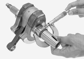
Clean off any oil from the crankshaft journals. Measure and record the crankshaft main journal O.D.
SERVICE LIMIT: 33.975 mm (1.3376 in)
Calculate the oil clearance between the crankshaft main journal and main journal bearing.
SERVICE LIMIT: 0.075 mm (0.0030 in)
If the clearance exceeds the service limit, select the main journal bearing (page 14-7).
[2]
Press the main journal bearings [1] toward the inside of the crankcase.
[1]
14-7 CRANKCASE/CRANKSHAFT/TRANSMISSION/BALANCER
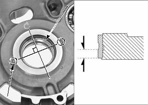
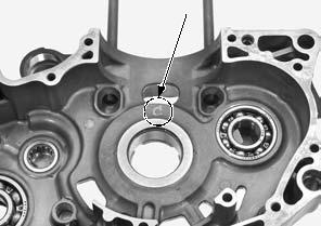
Measure and record the crankcase main journal bearing support I.D. at 90 degrees to the index mark [1].
SERVICE LIMIT: 38.036 mm (1.4975 in)
90°
• Crankshaft and crankcase are replaced • Crankcase only is replaced • Crankshaft only is replaced • Main journal bearings only are replaced
Carefully refer to the following instructions and tables for main journal bearing selection.
Record the bearing support I.D. code [1] letter.
Letters A, B or C on each crankcase is the code for the crankcase main journal bearing support I.D.
Cross-reference the crankshaft and crankcase codes to determine the replacement bearing color.
14-8 CRANKCASE/CRANKSHAFT/TRANSMISSION/BALANCER
BEARING THICKNESS:
O.S. D (Red): Thick
O.S. E (Green):
O.S. F (Yellow):
O.S. G (Pink): Middle
A (Blue): B (Black): C (Brown): Thin
BEARING INSTALLATION
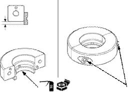
Apply engine oil to new bearing [1] surface.
Set new bearings to the metal installer as shown.
TOOL:
Metal installer set 070MF-KYJ0100
Tighten the bolts [2] alternately in several steps.
Set the bearings [1] and special tools assembly on inside of the crankcase, fitting the bearing edge in the crankcase main journal.
Align the mating line of the bearings with the index mark [2] on the crankcase as shown.
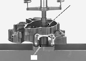
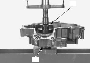
Set the crankcase and special tools on the hydraulic press.
TOOLS:
[1] Metal installer set 070MF-KYJ0100
[2] Base, 42 mm 07GAF-SD40200
Make sure the metal installer mating line is aligned with the index mark on the crankcase.
IDENTIFICATION COLOR
4.0 mm
(0.16 in)
[1]
[2]
[1]
[2]
14-9 CRANKCASE/CRANKSHAFT/TRANSMISSION/BALANCER
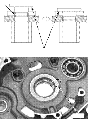
Press the bearings [1] until the metal installer flange [2] is fully seated.
[1]
Make sure the bearing mating line is aligned with the index mark on the crankcase.
Check the oil clearance (page 14-7).
After selecting new bearings, recheck the oil clearance.
Incorrect clearance can cause severe engine damage.
Install the following:
– Crankshaft (page 14-6) – Transmission (page 14-11) – Balancer shaft (page 14-14)
TRANSMISSION
REMOVAL/DISASSEMBLY
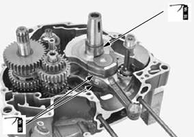
Separate the crankcase halves (page 14-4).
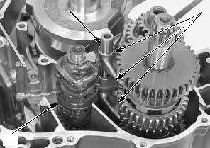
Pull the shift fork shaft [1] and remove it from the shift forks.
Remove the shift forks [2] and shift drum [3].
[3]
Remove the mainshaft assembly [1] and countershaft assembly [2] together.
[2]
Align
[1]
[2]
14-10
|
|||||||||||||||||||||||||||||||||||||||||||||||||||||||||||||||||||||||||||||||||||||||||||||||||||||||||||||||||||||||||||||||||||||||||||||||||||||||||||||||||||||||||||||||||||||||||||||||||||||||||||||||||||||||||||||||||||||||||||||||||||||||||||||||||||||||||||||||||||||||||||||||||||||||||||||||||||||||||||||||||||||||||||||||||||||||||||||||||||||||||||||||||||||||||||||||||||||||||||||||||||||||||||||
|
Последнее изменение этой страницы: 2016-04-08; просмотров: 679; Нарушение авторского права страницы; Мы поможем в написании вашей работы! infopedia.su Все материалы представленные на сайте исключительно с целью ознакомления читателями и не преследуют коммерческих целей или нарушение авторских прав. Обратная связь - 216.73.216.41 (0.006 с.) |


