Engine does not start (MIL does not blink) 1. ECM power Input voltage Inspection 


Мы поможем в написании ваших работ!


ЗНАЕТЕ ЛИ ВЫ?

Engine does not start (MIL does not blink) 1. ECM power Input voltage Inspection


Disconnect the ECM 33P (Black) connector [1]                    
  [1]                
(page 4-50).                    
                     
Turn the ignition switch ON and engine stop switch                    
" ".                        
Measure the voltage at the ECM 33P (Black)           Bl/Bu        
                   
connector of the wire side and ground.                    
Connection: Black/blue (+) – Ground (–)                    
Standard: Battery voltage                    
TOOL:                        
Test probe 07ZAJ-RDJA110                    
Does the standard voltage exist?                    
YES –GO TO STEP 2.                    
                   
NO –• Open circuit in Black/blue wire                  
  Faulty ignition switch                  
  • Blown main fuse (30 A)                  
  • Blown FI, IGN fuse (10 A)                  
  • Faulty engine stop switch                  
2. Sensor Unit Power Line Inspection                  
Turn the ignition switch OFF.                    
                   
            [1]    
Check for continuity between the ECM 33P (Black)        
                   
connector [1] of the wire side and ground.                    
Connection: Yellow/red – Ground                    
TOOL:                        
Test probe 07ZAJ-RDJA110                    
    Y/R            
                   
Is there continuity?                    
YES –Short circuit in Yellow/red wire                    
NO –GO TO STEP 3.                    
                         

ECM Ground Line Inspection


Turn the ignition switch OFF.                
          [1]    
Check for continuity between the ECM 33P (Black)            
               
connector [1] of the wire side and ground. G          
Connection: Green/black – Ground                
    Green – Ground                
    Green – Ground                
      G   G/Bl        
                 
TOOL:                    
Test probe 07ZAJ-RDJA110                
Is there continuity?                
YES –Replace the ECM with a known good one,                
  and recheck.                
NO –• Open circuit in Green/black wire                
               

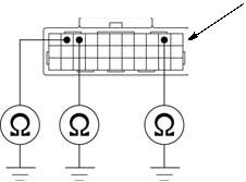
• Open circuit in Green wires


4-49


PGM-FI SYSTEM


REMOVAL/ INSTALLATION      
Remove the reserve tank cover (page 2-4).      
[1]    
Turn the ignition switch OFF.    
     
Disconnect the ECM 33P (Black) connector [1].      
Remove the rubber holder [2] and ECM [3].      
Remove the ECM from the rubber holder.      
Installation is in the reverse order of removal.      


[2]    
  [3]  


4-50


IGNITION SYSTEM


SERVICE INFORMATION·····························5-2 IGNITION SYSTEM INSPECTION ················5-4


TROUBLESHOOTING···································5-2 IGNITION TIMING ·········································5-6


SYSTEM LOCATION·····································5-3 IGNITION COIL ·············································5-6


SYSTEM DIAGRAM ······································5-3


5-1


IGNITION SYSTEM

SERVICE INFORMATION


GENERAL


• When servicing the ignition system, always follow the steps in the troubleshooting table (page 5-2).

• A faulty ignition system is often related to poorly connected or corroded connections. Check those connections before proceeding.


TROUBLESHOOTING


• Inspect the following before diagnosing the system.

– Faulty spark plug

– Loose spark plug cap or spark plug wire connection

– Water got into the spark plug cap (Leaking the ignition coil secondary voltage)


• "Initial voltage" of the ignition primary coil is the battery voltage with the ignition switch turned ON and engine stop switch " " (The engine is not cranked by the starter motor).


  Unusual condition   Probable cause (Check in numerical order)
Ignition coil No initial voltage with the ignition 1. Faulty ignition switch
primary voltage switch turned ON and engine stop 2. An open circuit in Black/blue wire between the ignition coil
  switch " " (Other electrical   and engine stop switch
  components are normal). 3. An open circuit in Black/green or Black/red wires between
      the engine stop switch and ignition switch
    4. Loose or poor connection of the primary terminal, or an
      open circuit in the primary coil
    5. Faulty ECM (in case when the initial voltage is normal with
      the ECM connector disconnected).
    6. Faulty engine stop switch
  Initial voltage is normal, but it drops by 1. Incorrect peak voltage adaptor connections (System is
  2 – 4 V while cranking the engine.   normal if measured voltage is over the specifications with
      reverse connections).
    2. Battery is undercharged (Voltage drops largely when the
      engine is started).
    3. No voltage between the Black/blue (+) wire and body
      ground (–) at the ECM connector or poor connection of the
      ECM connector
    4. An open circuit or loose connection in Green or Green/
      black wire at the ECM
    5. An open circuit or loose connection in Green/red wire
      between the ignition coil and ECM
    6. Faulty sidestand switch or neutral switch or related wires
    7. Faulty CKP sensor (Measure peak voltage)
    8. Faulty ECM (in case when above No. 1 through 7 are
      normal).
  Initial voltage is normal but there is no 1. Incorrect peak voltage adaptor connections
  peak voltage while cranking the 2. Faulty peak voltage adaptor
  engine. 3. Faulty CKP sensor
    4. Faulty ECM (in case when above No. 1 through 3 are
      normal).
  Initial voltage is normal but peak 1. The multimeter impedance is too low; below 10 MΩ/DCV.
  voltage is lower than the standard 2. Cranking speed is too slow (Battery is undercharged).
  value. 3. The sampling timing of the tester and measured pulse were
      not synchronized (System is normal if measured voltage is
      over the standard voltage at least once).
    4. Faulty ECM (in case when above No. 1 through 3 are
      normal).
  Initial and peak voltages are normal 1. Faulty spark plug or leaking ignition coil secondary current
  but no spark jumps. 2. Faulty ignition coil
CKP sensor Peak voltage is lower than standard 1. The multimeter impedance is too low; below 10 MΩ/DCV.
  value. 2. Cranking speed is too low. (Battery is undercharged.)
    3. The sampling timing of the tester and measured pulse were
      not synchronized (System is normal if measured voltage is
      over the standard voltage at least once).
    4. Faulty CKP sensor (in case when above No.1 through 3
      are normal).
  No peak voltage 1. Faulty peak voltage adapter
    2. Faulty CKP sensor


5-2


IGNITION SYSTEM


SYSTEM LOCATION

IGNITION SWITCH


CLUTCH SWITCH


BANK ANGLE SENSOR


IGNITION COIL


SPARK PLUG


CKP SENSOR


NEUTRAL SWITCH


SYSTEM DIAGRAM


ENGINE STOP SWITCH


ECM


BATTERY


MAIN FUSE (30 A)


FI, IGN FUSE (10 A)


SIDESTAND


SWITCH


                    IGNITION SWITCH       SIDESTAND Bl: Black  
                              SWITCH Bu: Blue  
            R/W                  
                                      G: Green  
                                       
      MAIN FUSE (30 A)                      
            Bl/R             Lg: Light green  
                                     
                                      O: Orange  
                                      R: Red  
      FI, IGN FUSE (10 A)                      
                          W: White  
BATTERY                      
            BANK G/W   G    
                             
        Bl/G                     Y: Yellow  
                         
                                 
            ENGINE STOP   ANGLE         Br: Brown  
                       
  SWITCH SENSOR    
         
         
  Bl/Bu        


  IGNITION                                                  
  COIL                                                  
                              G/R                    
      W/Y   Bl/Bu                   G/Bl     NEUTRAL  


                            G/O                      
                R/Bu                   DIODE  
      Bu/Y     G/R             G     G    


                                                Lg/R    
  CKP                   ECM                            
                                          NEUTRAL  
                                             
  SENSOR                                            
SPARK                                           SWITCH  
                                               

PLUG


5-3


IGNITION SYSTEM

IGNITION SYSTEM INSPECTION

• If there is no spark at the plug, check all connections        
       
[2]    
for loose or poor contact before measuring the peak    
     
voltage.      
• Use a commercially available digital multimeter with      
an impedance of 10 MΩ/DCV minimum.      

The display value differs depending upon the internal impedance of the multimeter.


• If using the Imrie diagnostic tester (model 625), follow the manufacturer’s instructions.


Connect the peak voltage adaptor [1] to the digital multimeter [2], or use the Imrie diagnostic tester.


TOOL:      
Imrie diagnostic tester (model 625) or    
[1]  
Peak voltage adaptor 07HGJ-0020100  
   

with commercially available digital multimeter (impedance 10 MΩ/DCV minimum)


Поделиться:


Последнее изменение этой страницы: 2016-04-08; просмотров: 310; Нарушение авторского права страницы; Мы поможем в написании вашей работы!

infopedia.su Все материалы представленные на сайте исключительно с целью ознакомления читателями и не преследуют коммерческих целей или нарушение авторских прав. Обратная связь - 3.147.66.178 (0.064 с.)