Заглавная страница Избранные статьи Случайная статья Познавательные статьи Новые добавления Обратная связь FAQ Написать работу КАТЕГОРИИ: ТОП 10 на сайте Приготовление дезинфицирующих растворов различной концентрацииТехника нижней прямой подачи мяча. Франко-прусская война (причины и последствия) Организация работы процедурного кабинета Смысловое и механическое запоминание, их место и роль в усвоении знаний Коммуникативные барьеры и пути их преодоления Обработка изделий медицинского назначения многократного применения Образцы текста публицистического стиля Четыре типа изменения баланса Задачи с ответами для Всероссийской олимпиады по праву 
Мы поможем в написании ваших работ! ЗНАЕТЕ ЛИ ВЫ?
Влияние общества на человека
Приготовление дезинфицирующих растворов различной концентрации Практические работы по географии для 6 класса Организация работы процедурного кабинета Изменения в неживой природе осенью Уборка процедурного кабинета Сольфеджио. Все правила по сольфеджио Балочные системы. Определение реакций опор и моментов защемления |
Engine stall, hard to start, rough idlingСодержание книги
Поиск на нашем сайте
• Deteriorated fuel • Bent or kinked fuel hose/fuel tank breather hose • Faulty IACV • Intake air leak • Faulty ignition system • Faulty MAP sensor • Faulty charging system
Backfiring or misfiring during acceleration • Faulty ignition system
Engine lacks power • Bent or kinked fuel hose/fuel tank breather hose • Clogged fuel filter • Faulty fuel pump or its drive circuit • Faulty injector • Faulty ignition system • Clogged air cleaner element
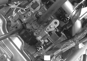
7-2 FUEL SYSTEM
COMPONENT LOCATION
7.0 N·m (0.7 kgf·m, 5.2 lbf·ft)
3.0 N·m (0.3 kgf·m, 2.2 lbf·ft)
27 N·m (2.8 kgf·m, 20 lbf·ft)
7-3 FUEL SYSTEM
FUEL LINE INSPECTION
FUEL PRESSURE RELIEVING
Before disconnecting fuel feed hose, relieve pressure from the system as follows.
1. Turn the ignition switch OFF.
2. Disconnect the fuel pump 3P (Black) connector [1].
3. Start the engine, and let it idle until the engine stalls.
4. Turn the ignition switch OFF.
5. Disconnect the battery negative (–) cable (page 19-
4).
[1]
QUICK CONNECT FITTING REMOVAL
Do not bend or twist fuel feed hose.
[2]
7-4 FUEL SYSTEM
QUICK CONNECT FITTING INSTALLATION
• Always replace the retainer and joint rubber of the quick connect fitting when the fuel feed hose is disconnected.
• Replace the retainer and joint rubber with the same manufacturer’s item that was removed.
• Do not bent or twist fuel feed hose.
1. Insert a new retainer [1] into the connector [2].
• Align new retainer locking pawls with the connector grooves.
[1]
[2]
Align
7-5 FUEL SYSTEM
2. Set a new joint rubber [1] to the joint [2] as shown.
Press the quick connect fitting [3] onto the pipe until both retainer pawls lock with a "CLICK".
• Align the quick connect fitting with the joint. • If it is hard to connect, put a small amount of engine oil on the joint end.
3. Make sure the connection is secure and that the pawls [1] are firmly locked into place; check visually and by pulling the connector.
4. Make sure the joint rubber [2] is positioned between the retainer [3] and joint flange [4] as shown.
5. Reposition the fuel tank [1] and tighten the three bolts [2].
FUEL PRESSURE NORMALIZATION
1. Connect the fuel pump 3P (Black) connector [1]. Connect the battery negative (–) cable (page 19-4). 2. Turn the ignition switch ON and engine stop switch "
• Do not start the engine.
The fuel pump will run for about 2 seconds, and fuel pressure will rise.
Repeat 2 or 3 times, and check that there is no leakage in the fuel supply system.
Turn the ignition switch OFF.
[1]
[3]
[1]
[2]
[2]
[1]
[4]
[2]
[1]
7-6 FUEL SYSTEM
FUEL PRESSURE TEST
STANDARD: 343 kPa (3.5 kgf/cm2, 50 psi)
If the fuel pressure is higher than specified, replace the fuel pump assembly.
If the fuel pressure is lower than specified, inspect the following:
– Fuel line leaking – Pinched or clogged fuel feed hose or fuel tank breather hose – Fuel pump unit (page 7-8) – Clogged fuel filter
After inspection, relieve the fuel pressure (page 7-4).
Remove the fuel pressure gauge, attachment and manifold from the fuel pump.
Connect the quick connect fitting (page 7-5).
Wipe off spilled out gasoline.
FUEL FLOW INSPECTION
Relieve the fuel pressure and disconnect the quick connect fitting (page 7-4).
Connect the special tool to the fuel pump joint.
TOOL:
[1] Hose attachment, 8 mm/9 mm 07ZAJ-S7C0100
Place the end of the hose into an approved gasoline container.
Temporarily connect the battery negative (–) cable and fuel pump 3P (Black) connector.
Turn the ignition switch ON and engine stop switch "
• The fuel pump operates for 2 seconds. Repeat 5 times to meet the total measuring time.
• Return fuel to the fuel tank when the first fuel is flowed.
Amount of fuel flow:
83 cm3 (2.81 US oz, 2.92 Imp oz) minimum/ 10 seconds at 12 V
If fuel flow is less than specified, inspect the following:
– Fuel pump unit (page 7-8) – Clogged fuel filter
Connect the quick connect fitting (page 7-5).
[1]
7-7 FUEL SYSTEM
FUEL TANK
REMOVAL/INSTALLATION
Relieve the fuel pressure and disconnect the quick connect fitting (page 7-4).
Lift up the fuel tank [1] and release the fuel feed hose [2] from the hose clamps [3].
Disconnect the fuel tank breather hose [4] and remove the fuel tank.
Install the fuel tank in the reverse order of removal. Connect the quick connect fitting (page 7-5).
FUEL PUMP UNIT
SYSTEM INSPECTION
Turn the ignition switch ON and engine stop switch "
If the fuel pump does not operate, inspect as follows: Turn the ignition switch OFF.
Disconnect the fuel pump 3P (Black) connector [1]. Turn the ignition switch ON and engine stop switch "
Measure the voltage at the fuel pump 3P (Black) connector terminals of the wire side.
CONNECTION: Brown/red (+) – Green (–) STANDARD: Battery voltage
There should be standard voltage for a few seconds. If there is standard voltage, replace the fuel pump unit. If there is no standard voltage, inspect the following: – Main fuse (30 A) – FI, IGN fuse (10 A) – Ignition switch (page 20-11) – Engine stop switch (page 20-11) – Fuel pump relay (page 7-10) – Open circuit in Brown/red or Green wire
[1]
[4]
[3]
[1]
[3]
[2]
7-8 FUEL SYSTEM
REMOVAL/INSTALLATION
Do not disassemble the fuel pump.
Remove the fuel tank (page 7-8). Clean around the fuel pump.
Loosen the fuel pump mounting nuts [1] in a crisscross pattern in 2 or 3 steps and remove the nuts.
Remove the fuel pump unit [2] from the fuel tank, being careful not to damage the fuel level sensor float arm.
Remove the packing [1] from the fuel pump unit [2].
Install a new packing onto the fuel pump unit.
• Always replace the packing with a new one. • Be careful not to pinch the dirt and debris between the fuel pump unit and packing.
Install the fuel pump [1] into the fuel tank.
Install and tighten the fuel pump mounting nuts [2] to the specified torque in the sequence as shown.
TORQUE:12 N·m (1.2 kgf·m, 9 lbf·ft)
Install the fuel tank (page 7-8).
[2]
[2]
[1]
5
4
[1]
[2]
INSPECTION
7-9 FUEL SYSTEM
FUEL PUMP RELAY
INSPECTION
Remove the left side cover (page 2-3).
Remove the dust cover [1]
Remove the fuel pump relay [2].
[1]
Connect a 12 V battery to the fuel pump relay terminals as shown.
There should be continuity only when 12 V battery is connected.
If there is no continuity when the 12 V battery is connected, replace the fuel pump relay.
AIR CLEANER HOUSING
REMOVAL/INSTALLATION
Remove the sub-frame (page 2-12). Remove the bolts [1] and air cleaner housing. Installation is in the reverse order of removal.
TORQUE:
Air cleaner housing mounting bolt: 7.0 N·m (0.7 kgf·m, 5.2 lbf·ft)
[2]
7-10 FUEL SYSTEM
THROTTLE BODY
REMOVAL
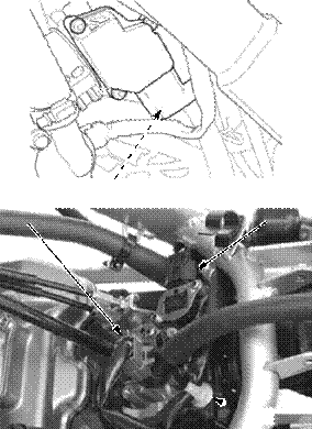
Remove the fuel tank (page 7-8). Disconnect the sensor unit 5P connector [1].
Disconnect the IACV 4P (Black) connector [1] and injector 2P (Gray) connector [2].
Release the wire band [3] from the clamp stay.
Loosen the throttle cable A adjuster lock nut [1] and adjuster [2] then disconnect the throttle cable A [3] from the throttle drum and cable stay.
Loosen the throttle cable B nut [4] then disconnect the throttle cable B [5] from the throttle drum and cable stay.
Loosen the connecting hose band screw [1] and insulator band screws [2], then remove the throttle body assembly [3].
[1]
[2]
7-11 FUEL SYSTEM
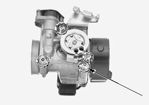
DISASSEMBLY/ASSEMBLY
• Do not remove the sensor unit unless it is replaced. • The throttle body/sensor unit is factory pre-set. Do
Remove the following
– Sensor unit (page 4-44) – Injector (page 7-14) – IACV (page 7-15)
Clean the air passage of the throttle body using compressed air.
• Cleaning the air passages and sensor hole with a piece of wire will damage the throttle body.
Check the air passage for clogs.
Disassemble and assemble the throttle body as following illustration.
THROTTLE CABLE STAY 3.4 N·m (0.3 kgf·m, 2.5 lbf·ft) INJECTOR
7-12 FUEL SYSTEM
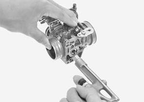
Install the throttle body insulator [1] to the throttle body by aligning the tab of the throttle body with the groove of the throttle body insulator.
• Install the throttle body insulator with "KZZ" mark [2] facing the cylinder head.
• Align the insulator band hole with the insulator boss.
INSTALLATION
Install the throttle body assembly [1] to the cylinder head by aligning the tab of the cylinder head with the groove of the throttle body insulator.
Tighten the insulator band screws [2] to the specified torque.
TORQUE:4.2 N·m (0.4 kgf·m, 3.1 lbf·ft)
After tightening the insulator band screws, check that the band ends are seated with each other.
Tighten the air cleaner connecting hose band screw [3] to the specified torque.
TORQUE:1.5 N·m (0.2 kgf·m, 1.1 lbf·ft)
Connect the throttle cables [1] to the throttle drum and throttle cable stay.
Tighten the throttle cable B nut [2] to the specified torque.
TORQUE:3.0 N·m (0.3 kgf·m, 2.2 lbf·ft)
<
|
||||||||||||||||||||||||||||||||||||||||||||||||||||||||||||||||||||||||||||||||||||||||||||||||||||||||||||||||||||||||||||||||||||||||||||||||||||||||||||||||||||||||||||||||||||||||||||||||||||||||||||||||||||||||||||||||||||||||||||||||||||||||||||||||||||||||||||||||||||||||||||||||||||||||||||||||||||||||||||||||||||||||||||||||||||||||||||||||||||||||||||||||||||||||||||||||||||||||||||||||||||||||||||||||||||||||||||||||||||||||||||||||||||||||||||||||||||||||||||||||||||||||||||||||||||||||||||||||||||||||||||||||||||||||||||||||||||||||||||||||||||||||||||||||||||||||||||||||||||||||||||||||||||||||||||||||||||||||||||||||||||||||||||||||||||||||||||||||||||||||||||||||||||||||||||||||||||||||||||||||||||||||||||||||||||||||||||||||||||||||||||||||||||||||||||||||||||||||||||||||||||||||||||||||||||||||||||||||||||||||||||||||||||||||||||||||||||||||||||||||||||||||||||||||||||||||||||||||||||||||||||||||||||||||||||||||||||||||||||||||||||||||||||||||||||||||||||||||||||||
|
|
Последнее изменение этой страницы: 2016-04-08; просмотров: 377; Нарушение авторского права страницы; Мы поможем в написании вашей работы! infopedia.su Все материалы представленные на сайте исключительно с целью ознакомления читателями и не преследуют коммерческих целей или нарушение авторских прав. Обратная связь - 18.119.213.60 (0.013 с.) |


 ".
".


 [3]
[3] 


 [1]
[1]
 [2]
[2] [4]
[4]


 1
1
 3
3 6
6

 [2]
[2]

 [1]
[1]


 [3]
[3]