Заглавная страница Избранные статьи Случайная статья Познавательные статьи Новые добавления Обратная связь FAQ Написать работу КАТЕГОРИИ: ТОП 10 на сайте Приготовление дезинфицирующих растворов различной концентрацииТехника нижней прямой подачи мяча. Франко-прусская война (причины и последствия) Организация работы процедурного кабинета Смысловое и механическое запоминание, их место и роль в усвоении знаний Коммуникативные барьеры и пути их преодоления Обработка изделий медицинского назначения многократного применения Образцы текста публицистического стиля Четыре типа изменения баланса Задачи с ответами для Всероссийской олимпиады по праву 
Мы поможем в написании ваших работ! ЗНАЕТЕ ЛИ ВЫ?
Влияние общества на человека
Приготовление дезинфицирующих растворов различной концентрации Практические работы по географии для 6 класса Организация работы процедурного кабинета Изменения в неживой природе осенью Уборка процедурного кабинета Сольфеджио. Все правила по сольфеджио Балочные системы. Определение реакций опор и моментов защемления |
Brake lever/pedal soft or spongyСодержание книги
Поиск на нашем сайте
• Air in hydraulic system • Leaking hydraulic system • Contaminated brake pad/disc • Worn caliper piston seal • Worn master cylinder piston cups • Worn brake pad/disc • Contaminated caliper • Contaminated master cylinder • Caliper not sliding properly • Low brake fluid level • Clogged fluid passage • Warped/deformed brake disc • Sticking/worn caliper piston • Sticking/worn master cylinder piston • Bent brake lever/pedal
Brake lever/pedal hard • Clogged/restricted brake system • Sticking/worn caliper piston • Sticking/worn master cylinder piston • Caliper not sliding properly • Warped/deformed brake disc • Bent brake lever/pedal
Brake drags • Contaminated brake pad/disc • Misaligned wheel • Badly worn brake pad/disc • Warped/deformed brake disc • Caliper not sliding properly • Clogged/restricted fluid passage • Sticking caliper piston
18-2 BRAKE SYSTEM
COMPONENT LOCATION
FRONT:
1.5 N·m (0.2 kgf·m, 1.1 lbf·ft)
30 N·m (3.1 kgf·m, 22 lbf·ft)
34 N·m (3.5 kgf·m, 25 lbf·ft)
9.8 N·m (1.0 kgf·m, 7.2 lbf·ft)
34 N·m (3.5 kgf·m, 25 lbf·ft)
REAR:
1.5 N·m (0.2 kgf·m, 1.1 lbf·ft)
34 N·m (3.5 kgf·m, 25 lbf·ft)
34 N·m (3.5 kgf·m, 25 lbf·ft)
14 N·m (1.4 kgf·m, 10 lbf·ft)
10 N·m (1.0 kgf·m, 7 lbf·ft)
18-3 BRAKE SYSTEM
BRAKE FLUID REPLACEMENT/AIR BLEEDING
BRAKE FLUID DRAINING
[4]
For rear brake: Remove the bolt [1] and reservoir [2].
Remove the cover screws [3], reservoir cover [4], set plate [5] and diaphragm [6].
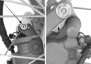
Connect a bleed hose [1] to the bleed valve [2].
Loosen the bleed valve and pump the brake lever or pedal until no more fluid flows out of the bleed valve. Tighten the bleed valve.
TORQUE: 5.4 N·m (0.6 kgf·m, 4.0 lbf·ft)
[2] [4]/[5]/[6]
[2]
[1]
Check the fluid level often while bleeding the brake to prevent air from being pumped into the system.
BRAKE FLUID FILLING/AIR BLEEDING
Close the bleed valve.
Fill the reservoir to the upper level line [1] with DOT 3 or DOT 4 brake fluid from a sealed container.
Connect a commercially available brake bleeder to the bleed valve.
Operate the brake bleeder and loosen the bleed valve.
If an automatic refill system is not used, add fluid when the fluid level in the reservoir is low.
Perform the bleeding procedure until the system is completely flushed/bled.
Close the bleed valve and operate the brake lever or pedal. If it still feels spongy, bleed the system again.
FRONT: REAR:
18-4 BRAKE SYSTEM
Do not release the lever or pedal until the bleed valve has been closed.
For rear brake:
If a brake bleeder is not available, use the following procedure:
Connect a bleed hose to the bleed valve.
Pressurize the system with the brake lever or pedal until lever or pedal resistance is felt.
1. Squeeze the brake lever or depress the brake pedal, open the bleed valve 1/4 turn and then close it.
2. Release the brake lever or pedal slowly and wait several seconds after it reaches the end of its travel.
3. Repeat the steps 1 and 2 until there are no air bubbles in the bleed hose.
After bleeding the system completely, tighten the bleed valve to the specified torque.
TORQUE: 5.4 N·m (0.6 kgf·m, 4.0 lbf·ft)
Fill the reservoir to the upper level line with DOT 3 or DOT 4 brake fluid.
Install the diaphragm, set plate and reservoir cover and tighten the screws to the specified torque.
TORQUE: 1.5 N·m (0.2 kgf·m, 1.1 lbf·ft)
Install the reservoir and bolt, then tighten it to the specified torque while pushing the reservoir against the stopper.
TORQUE: 10 N·m (1.0 kgf·m, 7 lbf·ft)
BRAKE PAD/DISC
FRONT BRAKE PAD REMOVAL/ INSTALLATION
Remove the pad pin [1].
Install the brake pads into the caliper so their ends rest into the pad retainer on the bracket properly.
[1]
18-5 BRAKE SYSTEM
Make sure the pad spring is installed correctly.
Always replace the brake pads in pairs to ensure even disc pressure.
Apply silicone grease to a new stopper ring [1] and install it into the pad pin [2] groove.
Install the pad pin by pushing in the pads against the pad spring to align the pad pin holes in the pads and caliper body.
Tighten the pad pin to the specified torque.
TORQUE: 17.2 N·m (1.8 kgf·m, 13 lbf·ft)
Operate the brake lever to seat the caliper pistons against the pads.
[2]
Make sure the pad spring is installed correctly.
Always replace the brake pads in pairs to ensure even disc pressure.
REAR BRAKE PAD REMOVAL/ INSTALLATION
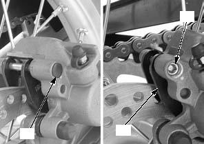
Remove the pad pin plug [1] and pad pin [2].
Remove the brake pads [3].
[1]
Apply silicone grease to a new stopper ring [1] and install it into the pad pin [2] groove.
Install the brake pads [3] into the caliper.
Install the pad pin by pushing in the pads against the pad spring to align the pad pin holes in the pads and caliper body.
Tighten the pad pin to the specified torque.
TORQUE: 17.2 N·m (1.8 kgf·m, 13 lbf·ft)
Install the pad pin plug [4].
Operate the brake pedal to seat the caliper pistons against the pads. [3]
[2]
[3]
[1]
[2]
[4]
BRAKE DISC INSPECTION
Visually inspect the brake disc for damage or cracks.
Measure the brake disc according to BRAKE SYSTEM SPECIFICATIONS (page 1-8) and replace if necessary.
18-6 BRAKE SYSTEM
FRONT MASTER CYLINDER
REMOVAL/INSTALLATION
Drain the brake fluid from the front brake hydraulic system (page 18-4).
Remove the following:
contamination. – Brake light switch connectors [5]
– Bolts [1] – Master cylinder holder [2] – Master cylinder [3]
Installation is in the reverse order of removal.
• Replace the sealing washers with new ones. • Align the edge of the master cylinder with the punch mark on the handlebar.
• Install the master cylinder and holder with its "UP" mark [4] facing up.
• Tighten the upper bolt first, then tighten the lower bolt.
TORQUE:
Front master cylinder holder bolt: 9.8 N·m (1.0 kgf·m, 7.2 lbf·ft)
Oil bolt:
34 N·m (3.5 kgf·m, 25 lbf·ft)
Fill and bleed the hydraulic system (page 18-4).
18-7 BRAKE SYSTEM
DISASSEMBLY/ASSEMBLY
Disassemble and assemble the front brake master cylinder as following illustration.
• Replace the master piston, spring, piston cups and snap ring as a set.
• Do not allow the piston cup lips to turn inside out. • Be certain the snap ring is firmly seated in the groove.
BRAKE LEVER
INSPECTION
Check the following parts for scoring, scratches, deterioration or damage.
– Master cylinder – Master piston – Piston cups – Spring – Boot
Measure the parts according to BRAKE SYSTEM SPECIFICATIONS (page 1-8) and replace if necessary.
REAR MASTER CYLINDER
When removing the oil bolt, cover the end of the hose to prevent contamination.
REMOVAL/INSTALLATION
[1]
18-8 BRAKE SYSTEM
– Cotter pin [1] – Joint pin [2] – Master cylinder mounting bolts [3]
– Snap ring [1] – Hose joint [2] – O-ring [3] – Rear master cylinder [4]
Installation is in the reverse order of removal.
• Replace the O-ring, master cylinder mounting bolts, cotter pin and sealing washers with new ones. • Apply brake fluid to the joint O-ring.
TORQUE:
Rear master cylinder mounting bolt: 14 N·m (1.4 kgf·m, 10 lbf·ft)
Oil bolt:
34 N·m (3.5 kgf·m, 25 lbf·ft)
Fill and bleed the hydraulic system (page 18-4).
DISASSEMBLY/ASSEMBLY
Disassemble and assemble the rear brake master cylinder as following illustration.
[2]
[2]
• Replace the master piston, spring, piston cups and snap ring as a set.
• Do not allow the piston cup lips to turn inside out. • Be certain the snap ring is firmly seated in the groove.
Standard push rod length:
64 - 65 mm
(2.52 - 2.56 in)
MASTER CYLINDER
MASTER PISTON
18-9 BRAKE SYSTEM
INSPECTION
Check the following parts for scoring, scratches, deterioration or damage.
– Master cylinder – Master piston – Piston cups – Spring
Measure the parts according to BRAKE SYSTEM
SPECIFICATIONS (page 1-8) and replace if necessary.
FRONT BRAKE CALIPER
REMOVAL/INSTALLATION
When removing the oil bolt, cover the end of the hose to prevent contamination.
Fill and bleed the hydraulic system (page 18-4).
DISASSEMBLY/ASSEMBLY
[3]
Disassemble and assemble the front brake caliper as following illustration.
CALIPER PISTONS CALIPER BRACKET
DUST SEALS
PISTON SEALS
BRACKET PIN
17.2 N·m (1.8 kgf·m, 13 lbf·ft)
BLEED VALVE
5.4 N·m (0.6 kgf·m, 4.0 lbf·ft)
CALIPER BODY
STOPPER RING
PAD PIN
17.2 N·m (1.8 kgf·m, 13 lbf·ft)
18-10 BRAKE SYSTEM
INSPECTION
Check the following parts for scoring, scratches, deterioration or damage.
– Caliper cylinders – Caliper pistons
Measure the parts according to BRAKE SYSTEM
SPECIFICATIONS (page 1-8) and replace if necessary.
REAR BRAKE CALIPER
When removing the oil bolt, cover the end of the hose to prevent contamination.
REMOVAL/INSTALLATION
Drain the brake fluid from the rear brake hydraulic system (page 18-4).
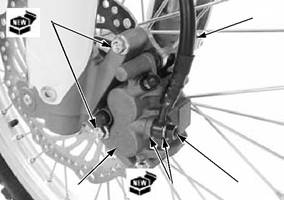
Remove the oil bolt [1], sealing washers [2], and brake hose [3].
Remove the rear wheel (page 17-4).
Remove the rear brake caliper [1] from the slide rail [2] of swingarm.
Installation is in the reverse order of removal.
• Replace the sealing washers with new ones.
TORQUE:
Oil bolt: 34 N·m (3.5 kgf·m, 25 lbf·ft)
Fill and bleed the hydraulic system (page 18-4).
[3]
18-11 BRAKE SYSTEM
DISASSEMBLY/ASSEMBLY
Disassemble and assemble the rear brake caliper as following illustration.
RETAINER
INSPECTION
Check the following parts for scoring, scratches, deterioration or damage.
– Caliper cylinder – Caliper piston
Measure the parts according to BRAKE SYSTEM SPECIFICATIONS (page 1-8) and replace if necessary.
BRAKE PEDAL
REMOVAL/INSTALLATION
Remove the following:
– Brake light switch return spring [1] – Brake pedal return spring [2]
18-12 BRAKE SYSTEM
– Cotter pin [1] – Joint pin [2] – Brake rod joint [3] – Stopper pin [4] – Washer [5]
– Brake pedal [1] – Dust seals [2]
Installation is in the reverse order of removal.
• Replace the dust seals and cotter pin with new ones.
• Install the dust seals in shown direction. • Apply grease to the brake pedal pivot sliding surface and dust seal lips.
[2]
[3]
[1]
[1]
18-13
BATTERY/CHARGING SYSTEM
SERVICE INFORMATION···························19-2
TROUBLESHOOTING·································19-2
SYSTEM LOCATION···································19-3
SYSTEM DIAGRAM ····································19-3
BATTERY····················································19-4 CHARGING SYSTEM INSPECTION ··········19-4 ALTERNATOR CHARGING COIL··············19-5 REGULATOR/RECTIFIER ··························19-6
19-1 BATTERY/CHARGING SYSTEM
SERVICE INFORMATION
GENERAL
• The battery gives off explosive gases; keep sparks, flames and cigarettes away. Provide adequate ventilation when charging. • The battery contains sulfuric acid (electrolyte). Contact with skin or eyes may cause severe burns. Wear protective clothing and a face shield.
– If electrolyte gets on your skin, flush with water. – If electrolyte gets in your eyes, flush with water for at least 15 minutes and call a physician immediately. • Electrolyte is poisonous. – If swallowed, drink large quantities of water or milk and call your local Poison Control Center or a physician immediately.
• Always turn OFF the ignition switch before disconnecting any electrical component. • Some electrical components may be damaged if terminals or connectors are connected or disconnected while the ignition switch is ON and current is present. • For extended storage, remove the battery, give it a full charge, and store it in a cool, dry space. For maximum service life, charge the stored battery every 2 weeks.
• For a battery remaining in a stored motorcycle, disconnect the negative battery cable from the battery terminal. • The maintenance free battery must be replaced when it reaches the end of its service life. • The battery can be damaged if overcharged or undercharged, or if left to discharge for a long period. These same conditions contribute to shortening the "life span" of the battery. Even under normal use, the performance of the battery deteriorates after 2 – 3 years. • Battery voltage may recover after battery charging, but under heavy load, battery voltage will drop quickly and eventually die out. For this reason, the charging system is often suspected as the problem. Battery overcharge often results from problems in the battery itself, which may appear to be an overcharging symptom. If one
|
||||||||||||||||||||||||||||||||||||||||||||||||||||||||||||||||||||||||||||||||||||||||||||||||||||||||||||||||||||||||||||||||||||||||||||||||||||||||||||||||||||||||||||||||||||||||||||||||||||||||||||||||||||||||||||||||||||||||||||||||||||||||||||||||||||||||||||||||||||||||||||||||||||||||||||||||||||||||||||||||||||||||||||||||||||||||||||||||||||||||||||||||||||||||||||||||||||||||||||||||||||||||||||||||||||||||||||||||||||||||||||||||||||||||||||||||||||||||||||||||||||||||||||||||||||||||||||||||||||||||||||||||||||||||||||||||||||||||||||||||||||||||||||||||||||||||||||||||||||||||||||||||||||||||||||||||||||||||||||||||||||||||||||||||||||||||||||||||||||||||||||||||||||||||||||||||||||||||||||||||||||||||||||||||||||||||||||||||||||||||||||||||||||||||||||||||||||||||||||||||||||||||||||||||||||||||||||||||||||||||||||||||||||||||||||||||||||||||||||||||||||||||||||||||||||||||||||||||||||||||||||||||||||||||||||||||||||||||||||||||||||||||||||||||||||||||||||||||||||||
|
|
Последнее изменение этой страницы: 2016-04-08; просмотров: 305; Нарушение авторского права страницы; Мы поможем в написании вашей работы! infopedia.su Все материалы представленные на сайте исключительно с целью ознакомления читателями и не преследуют коммерческих целей или нарушение авторских прав. Обратная связь - 3.12.73.221 (0.01 с.) |


 and diaphragm [4].
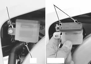


 [1]
[1]


 BRACKET PIN BOOT


 [2]
[2]
 [2]
[2]