Заглавная страница Избранные статьи Случайная статья Познавательные статьи Новые добавления Обратная связь FAQ Написать работу КАТЕГОРИИ: ТОП 10 на сайте Приготовление дезинфицирующих растворов различной концентрацииТехника нижней прямой подачи мяча. Франко-прусская война (причины и последствия) Организация работы процедурного кабинета Смысловое и механическое запоминание, их место и роль в усвоении знаний Коммуникативные барьеры и пути их преодоления Обработка изделий медицинского назначения многократного применения Образцы текста публицистического стиля Четыре типа изменения баланса Задачи с ответами для Всероссийской олимпиады по праву 
Мы поможем в написании ваших работ! ЗНАЕТЕ ЛИ ВЫ?
Влияние общества на человека
Приготовление дезинфицирующих растворов различной концентрации Практические работы по географии для 6 класса Организация работы процедурного кабинета Изменения в неживой природе осенью Уборка процедурного кабинета Сольфеджио. Все правила по сольфеджио Балочные системы. Определение реакций опор и моментов защемления |
Viscosity: SAE 10W-30 JASO T 903 standard: MAСодержание книги
Поиск на нашем сайте
Check that the O-ring [4] is in good condition, replace it if necessary.
Apply engine oil to the O-ring.
Install the oil filler cap.
ENGINE OIL CHANGE
Warm up the engine.
Stop the engine and remove the oil filler cap [1].
Place an oil pan under the engine to catch the engine oil, then remove the engine oil drain bolt [1]/sealing washer [2].
Drain the engine oil completely.
Install a new sealing washer onto the drain bolt.
Install and tighten the drain bolt to the specified torque.
TORQUE:24 N·m (2.4 kgf·m, 18 lbf·ft)
Fill the engine with the recommended engine oil (page 3-9).
ENGINE OIL CAPACITY:
Liters (1.5 US qt, 1.2 Imp qt) at draining Liters (1.6 US qt, 1.3 Imp qt) at oil filter change Liters (1.9 US qt, 1.6 Imp qt) at disassembly
Install the oil filler cap.
Check the oil level (page 3-9).
Make sure there are no oil leaks.
[1]
[1]
3-9 MAINTENANCE
ENGINE OIL FILTER
Installing the oil filter backwards will result in severe engine damage.
Install the oil filter spring [3] into the oil filter cover [4]. Install a new gasket [5] and oil filter cover.
Install the cover bolts and tighten them.
Fill the engine with the recommended engine oil (page 3-9).
ENGINE IDLE SPEED
• Inspect the idle speed after all other engine maintenance items have been performed and are within specifications.
• Before checking the idle speed, inspect the following items.
– No MIL blinking – Spark plug condition (page 3-5) – Secondary air supply system condition (page 3-11) – Crankcase breather system condition (page 3-4) – Air cleaner element condition (page 3-4) • The engine must be warm for accurate idle speed inspection. • This system eliminates the need for manual idle speed adjustment compared to previous designs.
Start the engine and let it idle. Check the idle speed.
IDLE SPEED: 1,450 ± 100 min-1 (rpm)
If the idle speed is out of the specification, check the following:
– Intake air leak or engine top-end problem (page 10-2)
– Throttle operation and freeplay (page 3-3) – IACV operation (page 7-16)
3-10 MAINTENANCE
RADIATOR COOLANT
Check the coolant level of the reserve tank with the engine running at normal operating temperature.
The level should be between the "UPPER" [1] and "LOWER" [2] level lines with the motorcycle in an upright position.
If the level is low, remove the reserve tank cap [3] and fill the tank to the "UPPER" level line with a 1:1 mixture of distilled water and antifreeze.
RECOMMENDED ANTIFREEZE:
High quality ethylene glycol antifreeze containing silicate-free corrosion inhibitors
Check to see if there are any coolant leaks when the coolant level decreases very rapidly.
If the reserve tank becomes completely empty, there is a possibility of air getting into the cooling system.
Be sure to remove any air from the cooling system (page 9-5).
COOLING SYSTEM
Check the radiator air passages for clogging or damage.
Straighten bent fins, and remove insects, mud or other obstructions with compressed air or low water pressure. Replace the radiator if the air flow is restricted over more than 20% of the radiating surface.
Inspect the water hoses for cracks or deterioration, and replace them if necessary.
Check the tightness of all water hose band screws (page 9-7).
[3]
[1]
[2]
SECONDARY AIR SUPPLY SYSTEM
• This model is equipped with a built-in secondary air supply system. The pulse secondary air supply system is located on the cylinder head cover [1].
• The secondary air supply system introduces filtered air into exhaust gases in the exhaust port [2]. The secondary air is drawn into the exhaust port whenever there is negative pressure pulse in the exhaust system. This charged secondary air promotes burning of the unburned exhaust gases and changes a considerable amount of hydrocarbons and carbon monoxide into relatively harmless carbon dioxide and water.
[1]
[2]
3-11 MAINTENANCE
If the hoses show any signs of heat damage, inspect the PAIR check valve in the cylinder head cover for damage (page 7-18).
Check the air suction hose [3] between the air cleaner and PAIR control solenoid valve for deterioration, damage or loose connections.
Make sure that the hoses are not kinked, pinched or cracked.
[3]
DRIVE CHAIN
Never inspect and adjust the drive chain while the engine is running.
Excessive chain slack, 50 mm (2.0 in) or more, may damage the frame.
ADJUSTMENT
[3]
3-12 MAINTENANCE
Make sure the same index lines [1] on both adjusting plates [2] are aligned with punch mark [3] in the swingarm.
Tighten the axle nut to the specified torque.
TORQUE:88 N·m (9.0 kgf·m, 65 lbf·ft)
Hold the drive chain adjusters [4] and tighten the lock nuts [5] to the specified torque.
TORQUE:27 N·m (2.8 kgf·m, 20 lbf·ft)
Recheck the drive chain slack and free wheel rotation.
Check the drive chain wear indicator label attached on the left swingarm.
If the drive chain adjuster cut-out [1] reaches red zone [2] of the indicator label, replace the drive chain with a new one.
CLEANING AND LUBRICATION
[2]
Clean the drive chain [1] with a chain cleaner designed specifically for O-ring chains or a neutral detergent. Use [1] a soft brush if the drive chain is dirty.
Do not use a steam cleaner, high pressure cleaner, wire brush, volatile solvent such as gasoline and benzene, abrasive cleaner or a chain cleaner NOT designed specifically for O-ring chains to clean the drive chain.
Inspect the drive chain for possible damage or wear.
Replace any drive chain that has damaged rollers, loose fitting links, or otherwise appears unserviceable.
Lubricate the drive chain with drive chain lubricant [2] designed specifically for use with O-ring chains, #80 – 90 gear oil or equivalent.
Do not use a chain lubricant NOT designed specifically for use with O-ring chains to lubricate the drive chain.
Wipe off the excess oil or drive chain lubricant.
3-13 MAINTENANCE
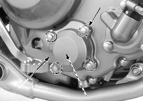
SPROCKET INSPECTION
Remove the drive sprocket cover (page 2-6).
Inspect the drive and driven sprocket teeth for wear or damage, replace if necessary.
Never use a new drive chain on worn sprockets.
Both chain and sprockets must be in good condition, or new replacement chain will wear rapidly.
Check the attaching bolts and nuts on the drive and driven sprockets.
If any are loose, tighten them to the specified torque.
TORQUE:
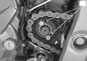
Drive sprocket fixing plate bolt [1]: 10 N·m (1.0 kgf·m, 7 lbf·ft)
Driven sprocket nut [2]:
50 N·m (5.1 kgf·m, 37 lbf·ft)
Install the drive sprocket cover (page 2-6).
DRIVE CHAIN SLIDER
The drive chain slider must be replaced if it is worn to the wear limit indicator [2] or wear limit line [3].
For drive chain slider replacement (page 17-10).
[1]
[2]
3-14 MAINTENANCE
BRAKE FLUID
Spilled fluid can damage painted, plastic or rubber parts. Place a rag over these parts whenever the system is serviced.
• Do not mix different types of fluid, as they are not compatible with each other.
• Do not allow foreign material to enter the system when filling the reservoir. • When the fluid level is low, check the brake pads for wear (page 3-16).
• A low fluid level may be due to wear of the brake pads. If the brake pads are worn and caliper pistons are pushed out, this accounts for a low fluid level. If the brake pads are not worn and fluid level is low, check the entire system for leaks (page 3-17).
FRONT BRAKE
Turn the handlebar to the left so that the reservoir is level and check the front brake fluid level through the sight glass.
If the level is near the "LOWER" level line [1], fill the recommended brake fluid.
Remove the following:
– Screws [2] – Reservoir cover [3] – Set plate [4] – Diaphragm [5]
Install the diaphragm, set plate and reservoir cover. Install and tighten the cover screws to the specified torque.
TORQUE:1.5 N·m (0.2 kgf·m, 1.1 lbf·ft)
3-15 MAINTENANCE
REAR BRAKE
Support the motorcycle on a level surface, and check the rear brake fluid level.
If the level is near the "LOWER" level line [1], fill the recommended brake fluid.
Remove the bolt [2] and reservoir [3].
Remove the cover screws [4], reservoir cover [5], set plate [6] and diaphragm [7].
Add DOT 3 or DOT 4 brake fluid from a sealed container to the "UPPER" level line [8].
Install the diaphragm, set plate and reservoir cover.
Install and tighten the cover screws to the specified [3] torque.
[9] [4]
TORQUE:1.5 N·m (0.2 kgf·m, 1.1 lbf·ft)
Install the reservoir and tighten the bolt to the specified torque while pushing the reservoir against the stopper [9].
TORQUE:10 N·m (1.0 kgf·m, 7 lbf·ft)
BRAKE PADS WEAR
Always replace the brake pads as a set to assure even disc pressure.
Always replace the brake pads as a set to assure even disc pressure.
FRONT BRAKE PADS
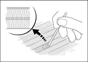
Check the front brake pads for wear.
Replace the front brake pads if either pad is worn to the wear limit groove [1].
For front brake pad replacement (page 18-5).
[1]
REAR BRAKE PADS
Check the rear brake pads for wear.
Replace the rear brake pads if either pad is worn to the wear limit groove [1].
For rear brake pad replacement (page 18-6).
[1]
3-16 MAINTENANCE
BRAKE SYSTEM
INSPECTION
Firmly apply the brake lever or pedal, and check that no air has entered the system.
If the lever or pedal feels soft or spongy when operated, bleed the air from the system.
For brake air bleeding (page 18-4).
Inspect the brake hose [1] and fittings for deterioration, cracks and signs of leakage. Tighten any loose fittings.
Replace hoses and fittings as required.
|
||||||||||||||||||||||||||||||||||||||||||||||||||||||||||||||||||||||||||||||||||||||||||||||||||||||||||||||||||||||||||||||||||||||||||||||||||||||||||||||||||||||||||||||||||||||||||||||||||||||||||||||||||||||||||||||||||||||||||||||||||||||||||||||||||||||||||||||||||||||||||||||||||||||||||||||||||
|
|
Последнее изменение этой страницы: 2016-04-08; просмотров: 348; Нарушение авторского права страницы; Мы поможем в написании вашей работы! infopedia.su Все материалы представленные на сайте исключительно с целью ознакомления читателями и не преследуют коммерческих целей или нарушение авторских прав. Обратная связь - 3.133.143.118 (0.01 с.) |


 [4]
[4]
 [3]
[3] [1] [2]


 [2]
[2]
 facing out.


 [2]
[2]  [1]
[1]


 Remove the drive sprocket cover (page 2-6).
 [3]
[3]