Заглавная страница Избранные статьи Случайная статья Познавательные статьи Новые добавления Обратная связь FAQ Написать работу КАТЕГОРИИ: ТОП 10 на сайте Приготовление дезинфицирующих растворов различной концентрацииТехника нижней прямой подачи мяча. Франко-прусская война (причины и последствия) Организация работы процедурного кабинета Смысловое и механическое запоминание, их место и роль в усвоении знаний Коммуникативные барьеры и пути их преодоления Обработка изделий медицинского назначения многократного применения Образцы текста публицистического стиля Четыре типа изменения баланса Задачи с ответами для Всероссийской олимпиады по праву 
Мы поможем в написании ваших работ! ЗНАЕТЕ ЛИ ВЫ?
Влияние общества на человека
Приготовление дезинфицирующих растворов различной концентрации Практические работы по географии для 6 класса Организация работы процедурного кабинета Изменения в неживой природе осенью Уборка процедурного кабинета Сольфеджио. Все правила по сольфеджио Балочные системы. Определение реакций опор и моментов защемления |
Connection: Yellow/blue – Green/whiteСодержание книги
Поиск на нашем сайте
6. Turn the ignition switch ON and engine stop switch "
Disconnect the jumper wire while the MIL blinking (within 10 seconds).
7. After disconnection of the jumper wire, the MIL will start short blinking.
Check if the MIL blinks.
[1]
[1]
[2]
If the MIL begins short blink (0.3 seconds), the TP sensor is reset successfully.
MIL ON
MIL OFF
If the MIL remains ON, the TP sensor is not reset, repeat the reset procedure from step 1.
8. Turn the ignition switch OFF.
9. Connect the ECT sensor 3P connector. 10.Install the dummy connector to the DLC.
4-45 PGM-FI SYSTEM
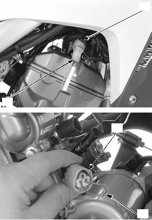
ECT SENSOR
Remove the ECT sensor while the engine is cold.
REMOVAL/INSTALLATION
Drain the coolant (page 9-5).
Disconnect the ECT sensor 3P connector [1]. Remove the ECT sensor [2] and sealing washer [3]. Installation is in the reverse order of removal.
• Replace the sealing washer with a new one.
TORQUE:
ECT sensor: 25 N·m (2.5 kgf·m, 18 lbf·ft)
[1]
Fill the cooling system with recommended coolant (page 9-5).
Wear insulated gloves and adequate eye protection. Keep flammable
materials away from the burner.
INSPECTION
Remove the ECT sensor [1] (page 4-46).
Heat the coolant with an electric heating element. Suspend the ECT sensor in heated coolant and check the continuity through the sensor as the coolant heats up.
• Soak the ECT sensor in coolant up to its threads with at least 40 mm (1.6 in) from the bottom of the pan to the bottom of the sensor.
• Keep temperature constant for 3 minutes before testing. A sudden change of temperature will result in incorrect readings. Do not let the thermometer [2] or ECT sensor touch the pan.
CONNECTION: A – B
Replace the ECT sensor if it is out of specifications by more than 10%.
Install the ECT sensor (page 4-46).
[2]
[1]
4-46 PGM-FI SYSTEM
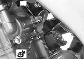
O2 SENSOR
• Do not get grease, oil or other materials in the O2 sensor air hole. • The O2 sensor may be damaged if dropped. Replace it with a new one, if dropped.
REMOVAL/INSTALLATION
• Handle the O2 sensor with care. • Do not service the O2 sensor while it is hot. • Do not use an impact wrench while removing or installing the O2 sensor, or it may be damaged.
Remove the left fuel tank shroud (page 2-4).
Disconnect the O2 sensor 1P (Black) connector [1].
Remove the wire band [2] from the frame.
[1]
Remove the O2 sensor [2].
Installation is in the reverse order of removal.
TORQUE:
O2 sensor: 25 N·m (2.5 kgf·m, 18 lbf·ft)
• Take care not to tilt the O2 sensor cap when connecting the cap to the O2 sensor.
• Do not turn the O2 sensor cap after connecting it.
[2]
[2]
4-47 PGM-FI SYSTEM
BANK ANGLE SENSOR
REMOVAL/INSTALLATION
• Install the bank angle sensor with its "UP" mark [8] facing up.
TORQUE:
Bank angle sensor mounting nut 9.0 N·m (0.9 kgf·m, 6.6 lbf·ft)
[8]
SYSTEM INSPECTION
Remove the bank angle sensor (page 4-48). Connect the bank angle sensor 2P connector. Place the bank angle sensor horizontal as shown. Start the engine.
Incline the bank angle sensor 70 ± 5° to the left or right.
The bank angle sensor is normal if the engine stops.
70° BANK ANGLE POSITION
70 ± 5°
HORIZONTAL
70 ± 5°
4-48 PGM-FI SYSTEM
ECM
ECM POWER/GROUND LINE INSPECTION
Before starting the inspection, check for loose or poor contact on the ECM 33P (Black) connector and recheck the MIL blinking.
|
|||||||||||||||||||||||||||||||||||||||||||||||||||||||||||||||||||||||||||||||||||||||||||||||||||||||||||||||||||||||||||||||||||||||||||||||||||||||||||||||||||||||||||||||||||||||||||||||||||||||||||||||||||||||||||||||||||||||||||||||||||
|
|
Последнее изменение этой страницы: 2016-04-08; просмотров: 341; Нарушение авторского права страницы; Мы поможем в написании вашей работы! infopedia.su Все материалы представленные на сайте исключительно с целью ознакомления читателями и не преследуют коммерческих целей или нарушение авторских прав. Обратная связь - 18.219.40.177 (0.006 с.) |

 ", then MIL will start blinking.