Заглавная страница Избранные статьи Случайная статья Познавательные статьи Новые добавления Обратная связь FAQ Написать работу КАТЕГОРИИ: ТОП 10 на сайте Приготовление дезинфицирующих растворов различной концентрацииТехника нижней прямой подачи мяча. Франко-прусская война (причины и последствия) Организация работы процедурного кабинета Смысловое и механическое запоминание, их место и роль в усвоении знаний Коммуникативные барьеры и пути их преодоления Обработка изделий медицинского назначения многократного применения Образцы текста публицистического стиля Четыре типа изменения баланса Задачи с ответами для Всероссийской олимпиады по праву 
Мы поможем в написании ваших работ! ЗНАЕТЕ ЛИ ВЫ?
Влияние общества на человека
Приготовление дезинфицирующих растворов различной концентрации Практические работы по географии для 6 класса Организация работы процедурного кабинета Изменения в неживой природе осенью Уборка процедурного кабинета Сольфеджио. Все правила по сольфеджио Балочные системы. Определение реакций опор и моментов защемления |
Radial: 2.0 mm (0.08 in) or less Axial: 2.0 mm (0.08 in) or lessСодержание книги
Поиск на нашем сайте
Tighten the spokes in 2 or 3 progressive steps.
TOOL:
Spoke wrench, 5.8 x 6.1 mm 07701-0020300
TORQUE: 3.7 N·m (0.4 kgf·m, 2.7 lbf·ft)
SHOCK ABSORBER
REMOVAL/INSTALLATION
Raise the rear wheel off the ground by placing a work stand or box under the frame.
Remove the sub-frame (page 2-12).
Remove the upper mounting nut [1] and bolt [2]. Remove the lower mounting nut [3], bolt [4] and shock absorber [5].
Installation is in the reverse order of removal.
TORQUE:
Shock absorber upper mounting nut: 54 N·m (5.5 kgf·m, 40 lbf·ft)
Shock absorber lower mounting nut: 44 N·m (4.5 kgf·m, 32 lbf·ft)
[1]/[2]
INSPECTION
Inspect the following parts for damage, abnormal wear, deformation, oil leakage or bend.
– Damper rod – Damper unit – Bushing
If the shock absorber is replaced, refer to shock absorber disposal procedure (page 17-7).
17-6 REAR WHEEL/SUSPENSION
SHOCK ABSORBER DISPOSAL PROCEDURE
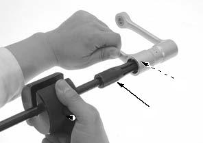
Center punch the damper case to mark the drilling point as shown.
Wrap the shock absorber [1] inside a plastic bag. Support the shock absorber upright in a vise as shown. Through the open end of the bag, insert a hand drill with a sharp 3 mm drill bit.
• Point the drill hole away from you to prevent debris getting in your eyes.
Hold the bag around the hand drill and briefly run it inside the bag; this will inflate the bag with air from the motor and help keep the bag from getting caught in the bit when you start.
Drill into the shock absorber at the center punch mark to purge the nitrogen gas.
Once all the nitrogen gas has been purged from the shock absorber and it is no longer under pressure, the item can be disposed of.
SHOCK LINKAGE
REMOVAL/INSTALLATION
Raise the rear wheel off the ground by placing a work stand or box under the frame and support the swingarm.
Remove the rear brake pedal return spring [1].
Remove the following:
– Shock absorber lower mounting nut/bolt [1] – Shock link-to-shock arm nut/bolt/washer [2] – Shock arm-to-swingarm nut/bolt/washer [3] – Shock arm [4] – Shock link-to-frame nut/bolt [5] – Shock link [6]
Installation is in the reverse order of removal.
• Apply engine oil to the shock arm-to-swingarm nut threads. • Before tightening the nuts to the specified torque, install all the nuts, bolts and washers.
TORQUE:
Shock link-to-frame nut:
44 N·m (4.5 kgf·m, 32 lbf·ft) Shock arm-to-swingarm nut:
74 N·m (7.5 kgf·m, 55 lbf·ft) Shock link-to-shock arm nut:
44 N·m (4.5 kgf·m, 32 lbf·ft)
Shock absorber lower mounting nut: 44 N·m (4.5 kgf·m, 32 lbf·ft)
[1]
[1]
17-7 REAR WHEEL/SUSPENSION
DISASSEMBLY/ASSEMBLY
Disassemble and assemble the shock linkage as following illustration.
• Install the swingarm side shock arm dust seals to the specified depth.
• Install other dust seals until they are fully seated on the bearings.
(17 X 24 X 17)
NEEDLE BEARING (17 X 24 X 25)
NEEDLE BEARING (17 X 24 X 25)
INSPECTION
Inspect the following parts for damage, abnormal wear, deformation or crack.
– Collars – Shock arm – Needle bearings – Shock link
BEARING REPLACEMENT
SHOCK ARM
Press the shock absorber and shock link side needle bearings [1] out of the shock arm using the special tool.
TOOLS:
Shock link and shock absorber side:
SHOCK ABSORBER/ SHOCK LINK SIDE
[1]
[2]
[3]/[4]
[5]
17-8 REAR WHEEL/SUSPENSION
Press the swingarm side needle bearings [1] out of the shock arm using the special tool.
SWINGARM SIDE
[5]
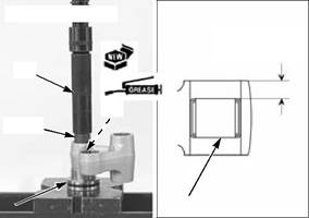
Apply grease to the needle rollers of new bearings [1].
Press in the bearing Carefully press each needle bearing in the pivot until with the marked the depth from the arm outer surface is 5.8 – 6.2 mm
side facing up. (0.23 – 0.24 in).
TOOLS: Shock Link and Shock Absorber side:
SHOCK ABSORBER/ SHOCK LINK SIDE
[2]
5.8 – 6.2 mm
(0.23 – 0.24 in)
[5] Fork seal driver attachment, 07746-0010300 27.2 mm
Apply grease to the needle rollers of new bearings [1].
Press in the bearing Carefully press each needle bearing in the pivot until with the marked the depth from the arm outer surface is 8.8 – 9.2 mm
side facing up. (0.35 – 0.36 in).
[5] Fork seal driver attachment, 07746-0010300 27.2 mm
SHOCK LINK
Remove the needle bearing [1] from the shock link using the special tools.
[1]
[5]
SWINGARM SIDE
8.8 – 9.2 mm
(0.35 – 0.36 in)
[2]
[1]
[3]/[4]
[1]
[2]
17-9 REAR WHEEL/SUSPENSION
Apply grease to the needle rollers of new bearings.
Press in the bearing Carefully press the needle bearing in the pivot until the with the marked depth from the link outer surface is 5.8 – 6.2 mm (0.23 –
side facing up. 0.24 in).
5.8 – 6.2 mm
(0.23 – 0.24 in)
[2] [3]/[4]
[1] 5.8 – 6.2 mm
(0.23 – 0.24 in)
SWINGARM
REMOVAL/INSTALLATION
Remove the following:
– Rear wheel (page 17-4) – Drive chain guide (page 17-12)
Remove the shock arm-to-swingarm nut [1], washer [2] and bolt [3].
Remove the screws [1] and brake hose guides [2].
[2]
[1]
[2]
[1]
17-10 REAR WHEEL/SUSPENSION
Remove the swingarm pivot nut [1]. [1] Remove the swingarm pivot bolt [2], then remove the swingarm from the frame.
Remove the swingarm dust seal caps [1].
Installation is in the reverse order of removal.
• Apply thin coat of grease to the pivot bolt outer surface. • Apply grease to the dust seal cap lips and fill the gap between the caps, collar and needle bearings with grease.
• Align the drive chain case slot with the swingarm hook.
• Apply engine oil to the threads of shock arm-to-swingarm nut.
TORQUE:
Swingarm pivot nut:
88 N·m (9.0 kgf·m, 65 lbf·ft) Shock arm-to-swingarm nut:
74 N·m (7.5 kgf·m, 55 lbf·ft)
Rear brake hose guide mounting screw: 1.2 N·m (0.1 kgf·m, 0.9 lbf·ft)
[2]
[1]
DISASSEMBLY/ASSEMBLY
Disassemble and assemble the swingarm as following illustration.
• Apply Honda Bond A or equivalent to the swingarm rubber cap mating surface with swingarm.
CHAIN CASE STAY
4.2 N·m (0.4 kgf·m, 3.1 lbf·ft)
SWINGARM RUBBER CAPS
CHAIN SLIDER
NEEDLE BEARINGS
DUST
17-11 REAR WHEEL/SUSPENSION
BEARING REPLACEMENT
Remove the pivot bearings [1] and dust seals [2] using the special tool.
Apply grease to the needle rollers of new bearings [1] and new dust seal [2] lips.
Install the dust seals to the specified depth with the marked side facing in.
Press the needle bearings to the specified depth with the marked side facing up, using the special tools.
[3]
[1]
DRIVE CHAIN GUIDE
REMOVAL/INSTALLATION
Remove the two nuts [1], screws [2] and chain slider guide [3].
Remove the bolts [4] and drive chain guide [5]. Installation is in the reverse order of removal.
• Replace the chain guide mounting bolts with new ones.
TORQUE:
Chain guide mounting bolt: 10 N·m (1.0 kgf·m, 7 lbf·ft)
Chain slider guide mounting nut: 2.5 N·m (0.3 kgf·m, 1.8 lbf·ft)
17-12 BRAKE SYSTEM
18-1 BRAKE SYSTEM
SERVICE INFORMATION
GENERAL
Frequent inhalation of brake pad dust, regardless of material composition, could be hazardous to your health. • Avoid breathing dust particles. • Never use an air hose or brush to clean brake assemblies. Use an OSHA-approved vacuum cleaner.
Spilled brake fluid will severely damage the plastic parts and painted surfaces. It is also harmful to some rubber parts. Be careful whenever you remove the reservoir cap; make sure the master cylinder reservoir is horizontal first.
• A contaminated brake disc or pad reduces stopping power. Discard contaminated pads and clean a contaminated disc with a high quality brake degreasing agent. • Always use fresh DOT 3 or DOT 4 brake fluid from a sealed container when servicing the system. Do not mix different types of fluid as they may not be compatible.
• Never allow contaminants (dirt, water, etc.) to enter an open reservoir. • Once the hydraulic system has been opened, or if the brake feels spongy, the system must be bled. • Always check brake operation before riding the motorcycle.
TROUBLESHOOTING
|
|||||||||||||||||||||||||||||||||||||||||||||||||||||||||||||||||||||||||||||||||||||||||||||||||||||||||||||||||||||||||||||||||||||||||||||||||||||||||||||||||||||||||||||||||||||||||||||||||||||||||||||||||||||||||||||||||||||||||||||||||||||||||||||||||||||||||||||||||||||||||||||||||||||||||||||||||||||||||||||||||||||||||||||||||||||||||||||||||||||||||||||||||||||||||||||||||||||||||||||||||||||||||||||||||||||||||||||||||||||||||||||||||||||||||||||||||||||||||||||||||||||||||||||||||||||||||||||||||||||||||||||||||||||||||||||||||||||||||||||||||||||||||||||||||||||||||||||||||||||||||||||||||||||||||||||||||||||||||||||||||||||||||||||||||||||||||||||||||||||||||||||||||||||||||||||||||||||||||||||||||||||||||||||||||||||||||||||||||||||||||||||||||||||||||||||||||||||||||||||||||||||||||||||||||||||||||||||||||||||||||||||||||||||||||||||||||||||||||||||||||||||||||||||||||||||||||||||||||||||||||||||||||||||||||||||||||||||||||||||||||||||||||||||||||||||||||||
|
|
Последнее изменение этой страницы: 2016-04-08; просмотров: 298; Нарушение авторского права страницы; Мы поможем в написании вашей работы! infopedia.su Все материалы представленные на сайте исключительно с целью ознакомления читателями и не преследуют коммерческих целей или нарушение авторских прав. Обратная связь - 3.149.239.70 (0.011 с.) |

 [1]
[1]
 [2]
[2]


 COLLAR (SWING NEEDLE BEARING
  ARM SIDE)


 [2]
[2]


 [3]
[3]
 [1]
[1]


 SCREW
SCREW COLLAR
 SEALS
SEALS


 [2]
[2]
 [1]
[1] [4]
[4]

 [4]/[5]
 [2]
[2]