Заглавная страница Избранные статьи Случайная статья Познавательные статьи Новые добавления Обратная связь FAQ Написать работу КАТЕГОРИИ: ТОП 10 на сайте Приготовление дезинфицирующих растворов различной концентрацииТехника нижней прямой подачи мяча. Франко-прусская война (причины и последствия) Организация работы процедурного кабинета Смысловое и механическое запоминание, их место и роль в усвоении знаний Коммуникативные барьеры и пути их преодоления Обработка изделий медицинского назначения многократного применения Образцы текста публицистического стиля Четыре типа изменения баланса Задачи с ответами для Всероссийской олимпиады по праву 
Мы поможем в написании ваших работ! ЗНАЕТЕ ЛИ ВЫ?
Влияние общества на человека
Приготовление дезинфицирующих растворов различной концентрации Практические работы по географии для 6 класса Организация работы процедурного кабинета Изменения в неживой природе осенью Уборка процедурного кабинета Сольфеджио. Все правила по сольфеджио Балочные системы. Определение реакций опор и моментов защемления |
Service limit: 6. 5 mm (0. 26 in)Содержание книги
Поиск на нашем сайте
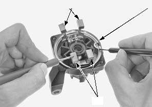
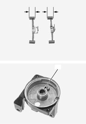
Check the bushing [1] of the rear cover for wear or damage.
Replace the starter motor as an assembly if necessary.
CONTINUITY:
[1]
[1]
6-7 ELECTRIC STARTER SYSTEM
STARTER RELAY SWITCH
INSPECTION
Remove the left side cover (page 2-3). Shift the transmission into neutral.
Turn the ignition switch ON and engine stop switch "
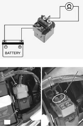
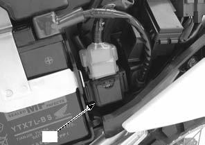
The coil is normal if the starter relay switch [1] clicks.
If you don't hear the starter relay switch "CLICK", inspect the starter relay switch using a procedure below.
[1]
GROUND LINE
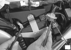
Disconnect the starter relay switch 4P (Red) connector [1].
Check for continuity between the following terminal of the wire harness side and ground when the starter switch is pushed.
CONNECTION: Green/red – Ground
If there is continuity under following conditions, the ground circuit is normal.
– When the transmission is in neutral (In neutral, there is a slight resistance due to the diode.)
– When the transmission is in gear with the clutch lever pulled in and sidestand retracted
STARTER RELAY INPUT VOLTAGE
Connect the starter relay switch 4P (Red) connector [1]. Turn the ignition switch ON and engine stop switch "
Measure the voltage between the following terminal at the starter relay switch 4P (Red) connector and ground.
CONNECTION: Yellow/red (+) – Ground (–)
STANDARD: Battery voltage
If the battery voltage appears only when the starter switch is pushed with the ignition switch ON and engine
stop switch "
[1]
[1]
6-8 ELECTRIC STARTER SYSTEM
OPERATION CHECK
Remove the starter relay switch (page 6-9).
Connect a fully charged 12 V battery to the starter relay switch as shown.
There should be continuity between the cable terminals when the battery is connected, and no continuity when the battery is disconnected.
REMOVAL/INSTALLATION
Remove the left side cover (page 2-3).
Disconnect the battery negative (-) terminal (page 19-4).
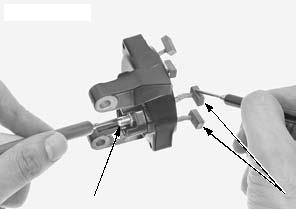
Disconnect the starter relay switch 4P (Red) connector [1].
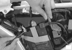
Release the starter relay switch [2] from the air cleaner housing.
Pull back the rubber cover [3]. Remove the bolts [4] and cables [5].
Remove the starter relay switch from the stays with the shock rubber.
Remove the starter relay switch from the shock rubber. Installation is in the reverse order of removal.
NEUTRAL DIODE
INSPECTION
Remove the left side cover (page 2-3).
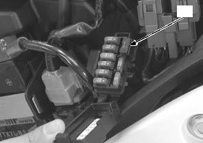
Open the fuse box cover and remove the neutral diode [1].
Check for continuity between the neutral diode terminals.
When there is continuity, a small resistance value will register.
If there is continuity, in direction shown by the arrow, the neutral diode is normal.
[2]
[1]
B
A
B C
6-9
FUEL SYSTEM
7-1 FUEL SYSTEM
SERVICE INFORMATION
GENERAL
• Work in a well ventilated area. Smoking or allowing flames or sparks in the work area or where gasoline is stored can cause a fire or explosion. • Do not snap the throttle valve from full open to full close after the throttle cable has been removed. It may cause incorrect idle operation.
• Bending or twisting the control cables will impair smooth operation and could cause the cables to stick or bind, resulting in loss of vehicle control.
• Do not damage the throttle body. It may cause incorrect throttle valve operation. • Seal the intake ports with tape or a clean cloth to keep dirt and debris from entering the engine after the throttle body has been removed.
• Prevent dirt and debris from entering the throttle bore and air passages after the throttle body has been removed. Clean them using a compressed air if necessary. • Do not loosen or tighten the white painted nut and screw of the throttle body. Loosening or tightening them can cause throttle valve and idle control failure.
• For fuel level sensor inspection (page 20-15). • Before disconnecting the fuel feed hose, relieve fuel pressure from the system by disconnecting the quick connect fitting from the system (page 7-4).
TROUBLESHOOTING
Engine won’t start • Deteriorated fuel • Bent or kinked fuel hose/fuel tank breather hose • Clogged fuel filter • Faulty fuel pump or its drive circuit • Intake air leak • Faulty injector • Faulty IACV • Faulty ignition system • Faulty ECM • Faulty bank angle sensor or its related circuit • Faulty fuel pump relay or its related circuit • Faulty engine stop switch or its related circuit • Blown FI, IGN fuse (10 A)
|
||||||||||||||||||||||||||||||||||||||||||||||||||||||||||||
|
|
Последнее изменение этой страницы: 2016-04-08; просмотров: 310; Нарушение авторского права страницы; Мы поможем в написании вашей работы! infopedia.su Все материалы представленные на сайте исключительно с целью ознакомления читателями и не преследуют коммерческих целей или нарушение авторских прав. Обратная связь - 18.119.132.236 (0.006 с.) |


 ". Push the starter switch.