Заглавная страница Избранные статьи Случайная статья Познавательные статьи Новые добавления Обратная связь FAQ Написать работу КАТЕГОРИИ: ТОП 10 на сайте Приготовление дезинфицирующих растворов различной концентрацииТехника нижней прямой подачи мяча. Франко-прусская война (причины и последствия) Организация работы процедурного кабинета Смысловое и механическое запоминание, их место и роль в усвоении знаний Коммуникативные барьеры и пути их преодоления Обработка изделий медицинского назначения многократного применения Образцы текста публицистического стиля Четыре типа изменения баланса Задачи с ответами для Всероссийской олимпиады по праву 
Мы поможем в написании ваших работ! ЗНАЕТЕ ЛИ ВЫ?
Влияние общества на человека
Приготовление дезинфицирующих растворов различной концентрации Практические работы по географии для 6 класса Организация работы процедурного кабинета Изменения в неживой природе осенью Уборка процедурного кабинета Сольфеджио. Все правила по сольфеджио Балочные системы. Определение реакций опор и моментов защемления |
Rear turn signal unit removal/ installationСодержание книги
Поиск на нашем сайте
Remove the rear fender (page 2-7).
Disconnect the rear turn signal 2P connector [1].
– Right side: Light blue – Left side: Orange
Remove the nut [2] and rear turn signal unit [3]. Installation is in the reverse order of removal.
TORQUE:
Turn signal unit mounting nut: 21 N·m (2.1 kgf·m, 15 lbf·ft)
Align the flats of the turn signal unit and turn signal unit stay.
[3] (Left
[1] side only)
Align
[3]
20-4 LIGHTS/METERS/SWITCHES
BRAKE/TAILLIGHT
For brake/taillight removal/installation (page 2-8).
BULB REMOVAL/INSTALLATION
Remove the rear fender (page 2-7).
Remove the brake/taillight mounting screws [1] and collars [2].
Remove the hook bolts [3] and collars [4].
Pull the tail cover/light unit [5] rearward while pulling up the rear upper fender [6].
Turn the bulb socket [1] counterclockwise and remove it.
While pushing in the bulb [2], turn it counterclockwise to remove it.
Installation is in the reverse order of removal.
TORQUE: Hook bolt:
21 N·m (2.1 kgf·m, 15 lbf·ft) Brake/taillight mounting screw: 4.5 N·m (0.5 kgf·m, 3.3 lbf·ft)
[2]
[5]
[2]
[1]
SPEEDOMETER
REMOVAL/INSTALLATION
Remove the headlight cowl (page 2-5). Release the wire bands [1] from the meter stay.
Remove the screws [2], washers [3] and speedometer [4] by disconnecting the speedometer 16P connector [5].
Remove the mounting rubbers [6]. Installation is in the reverse order of removal.
TORQUE:
Speedometer mounting screw: 1.0 N·m (0.1 kgf·m, 0.7 lbf·ft)
[2]
20-5 LIGHTS/METERS/SWITCHES
SYSTEM INSPECTION
Check for loose or poor contact terminals at the speedometer 16P connector.
When the ignition switch is turned ON, check that the meter segments turn on.
If the speedometer does not show the initial function, perform the power and ground line inspection of the speedometer (page 20-6).
If the speedometer shows the initial function but speedometer does not move when running, check the speedometer/VS sensor system inspection (page 20-8).
POWER/GROUND LINES INSPECTION
• Do not disconnect the speedometer 16P connector [1] during inspection. • After inspection, reposition the dust cover [2] securely.
Remove the dust cover.
With the speedometer 16P connector connected, check the following at the wire harness side connector.
– Open circuit in the Black wire – Open circuit in Black/red wire between the fuse box and ignition switch
– Blown METER, TAIL fuse (10 A)
20-6 LIGHTS/METERS/SWITCHES
– Open circuit in the Red wire – Blown ODO, CLOCK fuse (5 A) – Blown main fuse (30 A) – Open circuit in Red/white wire between the fuse box and starter relay switch
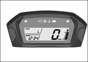
SPEEDOMETER DIGITAL CLOCK SET PROCEDURE
E TYPE:
Turn the ignition switch ON and engine stop switch "
Push and hold both the A button [1] and B button [2] until the speed and mileage units [3] start blinking.
Push the B button to select either "mph" & "mile", or "km/h" & "km" for the speedometer, odometer and trip meter.
Push the A button to confirm the unit setting, and then the display moves to the clock setting.
The hour digits [4] will start blinking. Push the B button until the desired hour is displayed.
Push and hold to advance the hour fast.
Push the A button, then the minute digits [5] start blinking.
Push the B button until the desired minute is displayed.
Push and hold to advance the minute fast.
Push both the A button and B button to complete the setting.
The time can also be set by turning the ignition switch OFF.
[3]
20-7
|
||||||||||||||||||||||||||||||||||||||||||||||||||||||||||||||||||||||||||||||||||||||||||||||||||||||||||||||||||||||||||||||||||||||||||||||||||||||||||||||||||||||||||||||||||||||||||||||||||||||||||||||||||||
|
|
Последнее изменение этой страницы: 2016-04-08; просмотров: 441; Нарушение авторского права страницы; Мы поможем в написании вашей работы! infopedia.su Все материалы представленные на сайте исключительно с целью ознакомления читателями и не преследуют коммерческих целей или нарушение авторских прав. Обратная связь - 216.73.216.41 (0.007 с.) |


 ".
".