Заглавная страница Избранные статьи Случайная статья Познавательные статьи Новые добавления Обратная связь FAQ Написать работу КАТЕГОРИИ: ТОП 10 на сайте Приготовление дезинфицирующих растворов различной концентрацииТехника нижней прямой подачи мяча. Франко-прусская война (причины и последствия) Организация работы процедурного кабинета Смысловое и механическое запоминание, их место и роль в усвоении знаний Коммуникативные барьеры и пути их преодоления Обработка изделий медицинского назначения многократного применения Образцы текста публицистического стиля Четыре типа изменения баланса Задачи с ответами для Всероссийской олимпиады по праву 
Мы поможем в написании ваших работ! ЗНАЕТЕ ЛИ ВЫ?
Влияние общества на человека
Приготовление дезинфицирующих растворов различной концентрации Практические работы по географии для 6 класса Организация работы процедурного кабинета Изменения в неживой природе осенью Уборка процедурного кабинета Сольфеджио. Все правила по сольфеджио Балочные системы. Определение реакций опор и моментов защемления |
Clutch lifter bearing replacementСодержание книги
Поиск на нашем сайте
Drive out the old bearing from the clutch lifter plate [1].
Drive in a new bearing [2] squarely with its marked side facing up.
After installation, apply engine oil to the bearing.
[3]
[4]/[5]
[1]
INSTALLATION
CLUTCH PLATE A CLUTCH LIFTER PIECE
12-11 CLUTCH/GEARSHIFT LINKAGE
Install the washer [1] to the mainshaft.
Apply molybdenum oil solution to the clutch outer guide [2] whole surface and install it to the mainshaft.
Apply engine oil to the needle bearing [3] rotating area and install it to the clutch outer guide.
Install the clutch outer [1] and washer [2].
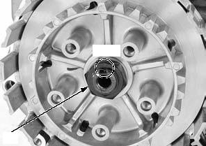
Apply engine oil to a new clutch center lock nut [1] threads and seating surface.
Install the clutch center [2], washer [3] and lock nut.
Hold the clutch center [1] with the special tool and tighten the lock nut [2] to the specified torque.
TORQUE:108 N·m (11.0 kgf·m, 80 lbf·ft)
[1]
[2]
[1]
[3]
[1]
[2]
[2]
[3]
[2]
12-12 CLUTCH/GEARSHIFT LINKAGE
Be careful not to Stake the lock nut [1] into the mainshaft groove. damage the
mainshaft threads.
Stake
[1]
Install the clutch lifter piece [1].
Install the spring seat [2] and judder spring [3] in the direction as shown.
Apply engine oil to the entire surface of clutch discs. Install the clutch disc B [4] and clutch plate B [5]. • Clutch disc B: larger I.D. • Clutch plate B: white paint on outer circumference
Install the clutch discs A [6] and plates A [7] alternately, starting with the clutch disc.
Install the clutch lifter plate [1].
Install the clutch springs [2] and bolts [3].
Tighten the clutch lifter plate bolts to the specified torque in a crisscross pattern in 2 or 3 steps.
TORQUE:12 N·m (1.2 kgf·m, 9 lbf·ft)
Install the right crankcase cover (page 12-8).
[2]/[3]
[1]
[2]
OUTSIDE
[1]
12-13 CLUTCH/GEARSHIFT LINKAGE
GEARSHIFT LINKAGE
REMOVAL
Remove the following:
– Drive sprocket cover (page 2-6)
– Clutch assembly (page 12-9)
Remove the pinch bolt [1] and gearshift pedal [2]. Clean off any dirt from the gearshift spindle serration.
Remove the gearshift spindle oil seal [1].
[1]
Be careful not to let Remove the shift drum stopper plate bolt [1].
crankcase.
12-14 CLUTCH/GEARSHIFT LINKAGE
INSPECTION
Check the return spring [1] and spindle arm spring [2] for fatigue or damage replace them if necessary. Check the gearshift spindle [3] for wear or bend. Check the spindle arm [4] for wear, damage or deformation.
Replace the gearshift spindle as an assembly if necessary.
Inspect the gearshift spindle needle bearing and replace if necessary.
GEARSHIFT SPINDLE NEEDLE BEARING REPLACEMENT Remove the gearshift spindle needle bearing [1] using the special tools.
[3] Bearing remover shaft, 15 mm 07936-KC10100 [4] Bearing remover head, 14 mm 07WMC-KFG0100
Drive in a new gearshift spindle needle bearing [1] into the left crankcase with the marked side facing up until it is fully seated using the special tools.
After installation, apply engine oil to the bearing.
[2]
[5]/[6]
[2] [1]
[4] [1]
[3]
[2]
[3] [1]
[2]
12-15 CLUTCH/GEARSHIFT LINKAGE
INSTALLATION
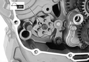
Apply locking agent to the shift drum stopper arm bolt [1] threads.
Install the return spring [2], washer [3] and stopper arm [4] while hooking the return spring at the stopper arm groove.
Install and tighten the bolt to the specified torque.
TORQUE:10 N·m (1.0 kgf·m, 7 lbf·ft)
Check the stopper arm for proper operation.
Hook [1]
Install the dowel pins [2] into the shift drum holes.
Install the shift drum stopper plate [3] while aligning its pin holes [4] with the dowel pins.
12-16 CLUTCH/GEARSHIFT LINKAGE
Apply engine oil to the gearshift spindle shaft [1] outer surface.
Install the gearshift spindle assembly and washer [2] to the crankcase by aligning the return spring ends with the spring pin.
Install the gearshift pedal [1] onto the gearshift spindle while aligning the punch marks.
Install and tighten the pinch bolt [2] securely. Install the following: – Clutch assembly (page 12-11) – Drive sprocket cover (page 2-6)
PRIMARY DRIVE GEAR
REMOVAL
Remove the clutch assembly (page 12-9).
Temporarily install the washer [1], clutch outer guide [2], needle bearing [3] and clutch outer [4].
Insert the gear holder [5] between the primary drive and driven gears.
Loosen the primary drive gear lock nut [6].
Remove the clutch outer, needle bearing, clutch outer guide and washer.
Remove the lock nut and washer [7].
Remove the primary drive gear [1].
[1]
[5] [6]/[7]
[1]/[2]/[3]/[4]
[1]
12-17 CLUTCH/GEARSHIFT LINKAGE
INSTALLATION
Apply engine oil to the primary drive gear [1] teeth.
Install the primary drive gear while aligning its punch mark with the crankshaft punch mark.
Install the washer [1].
Apply engine oil to the primary drive gear lock nut [2] threads and seating surface, then install it.
Temporarily install the washer [1], clutch outer guide [2], needle bearing [3] and clutch outer [4].
Insert the gear holder [5] between the primary drive and driven gears.
Tighten the primary drive gear lock nut [6] to the specified torque.
TORQUE:108 N·m (11.0 kgf·m, 80 lbf·ft)
Install the clutch assembly (page 12-11).
[1]/[2]/[3]/[4]
Align
[1]
12-18 ALTERNATOR/STARTER CLUTCH
SERVICE INFORMATION···························13-2 STATOR/CKP SENSOR ·····························13-4
TROUBLESHOOTING·································13-2 FLYWHEEL ·················································13-5
COMPONENT LOCATION··························13-2 STARTER CLUTCH ····································13-7
LEFT CRANKCASE COVER ······················13-3
13-1 ALTERNATOR/STARTER CLUTCH
SERVICE INFORMATION
GENERAL
• This section covers the removal and installation of the flywheel, alternator and starter clutch. These services can be done with the engine installed in the frame.
TROUBLESHOOTING
|
||||||||||||||||||||||||||||||||||||||||||||||||||||||||||||||||||||||||||||||||||||||||||||||||||||||||||||||||||||||||||||||||||||||||||||||||||||||||||||||||||||||||||||||||||||||||||||||||||||||||||||||||||||||||||||||||||||||||||||||||||||||||||||||||||||||||||||||||||||||||||||||||||||||||||||||||||||||||||||||||||||||||||||||||||||||||||||||||||||||||||||||||||||||||||||||||||||||||||||||||||||||||||||||||||||||||||||||||||||||||||||||||||||||||||||||||||||||||||||||||||||||||||||||||||||||||||||||||||||||||||||||||||||||||||||||||||||||||||||||||||||||||||||||||||||||||||||||||||||||||||||||||||||||||||||||||||||||||||||||||||||||||||||||||||||||||||||||||||||||||||||||||||||||||||||||||||||||||||||||||||||||||||||||||||||||||||||||||||||||||||||||||||||||||||||||||||||||||||||||||||||||||||||||||||||||||||||||||||||||||||||||||||||||||||||||||||||||||||||||||||||||||||||||||||||||||||||||||||||||||||||||||||||||||||||||||||||||||||||||||||||||||||||||||||||||||||||||||||||||
|
|
Последнее изменение этой страницы: 2016-04-08; просмотров: 511; Нарушение авторского права страницы; Мы поможем в написании вашей работы! infopedia.su Все материалы представленные на сайте исключительно с целью ознакомления читателями и не преследуют коммерческих целей или нарушение авторских прав. Обратная связь - 3.146.178.220 (0.01 с.) |


 [2]
[2]


 [3]
[3]


 [1]
[1]

 the removed parts [1] fall into the


 [1]
[1]


 [2]
[2]