Заглавная страница Избранные статьи Случайная статья Познавательные статьи Новые добавления Обратная связь FAQ Написать работу КАТЕГОРИИ: ТОП 10 на сайте Приготовление дезинфицирующих растворов различной концентрацииТехника нижней прямой подачи мяча. Франко-прусская война (причины и последствия) Организация работы процедурного кабинета Смысловое и механическое запоминание, их место и роль в усвоении знаний Коммуникативные барьеры и пути их преодоления Обработка изделий медицинского назначения многократного применения Образцы текста публицистического стиля Четыре типа изменения баланса Задачи с ответами для Всероссийской олимпиады по праву 
Мы поможем в написании ваших работ! ЗНАЕТЕ ЛИ ВЫ?
Влияние общества на человека
Приготовление дезинфицирующих растворов различной концентрации Практические работы по географии для 6 класса Организация работы процедурного кабинета Изменения в неживой природе осенью Уборка процедурного кабинета Сольфеджио. Все правила по сольфеджио Балочные системы. Определение реакций опор и моментов защемления |
DTC 8-1 (TP sensor low voltage)Содержание книги
Поиск на нашем сайте
TP Sensor System Inspection Turn the ignition switch ON and engine stop switch "
Check the TP sensor with the HDS pocket tester when the throttle fully closed.
Is about 0 V indicated?
YES – • Intermittent failure • Loose or poor contact on the sensor unit 5P connector
NO – GO TO STEP 2.
Sensor Unit Power Line Inspection
Check the sensor unit power line inspection (page 4-8).
Is the sensor unit power line normal?
YES – GO TO STEP 3.
NO – Replace or repair the abnormal circuit.
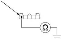
TP Sensor Output Line Short Circuit Inspection
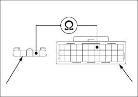
Check for continuity between the sensor unit 5P connector of the wire side and ground. Connection: Yellow – Ground
Is there continuity?
YES – Short circuit in Yellow wire
NO – GO TO STEP 4.
ECM
Y
4-15 PGM-FI SYSTEM
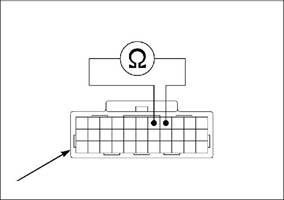
TP Sensor Output Line Open Circuit Inspection Disconnect the ECM 33P (Black) connector [1]. Check for continuity between the ECM 33P (Black) connector and sensor unit 5P connector [2] of the wire side.
TP Sensor Inspection Replace the sensor unit with a known good one (page 4-44). Connect the sensor unit 5P and ECM 33P (Black) connectors. Erase the DTC’s (page 4-5). Turn the ignition switch ON and engine stop switch " Check the TP sensor with the HDS pocket tester. Is DTC 8-1 indicated?
YES – Replace the ECM with a known good one
and recheck.
NO – Faulty original sensor unit (TP sensor)
DTC 8-2 (TP SENSOR HIGH VOLTAGE)
TP Sensor System Inspection Turn the ignition switch ON and engine stop switch "
Check the TP sensor with the HDS pocket tester.
Is about 5 V indicated?
TP Sensor Inspection Check that the TP sensor voltage increases continuously when moving the throttle from fully closed to fully opened using the data list menu of the HDS pocket tester. Is the voltage increase continuously?
YES – Intermittent failure
NO – Replace the TP sensor (sensor unit) with a
known good one and recheck.
4-16 PGM-FI SYSTEM
TP Sensor Resistance Inspection Turn the ignition switch OFF. Disconnect the ECM 33P (Black) connector [1]. Measure the resistance at the ECM 33P (Black) connector of the wire side. Connection: Yellow – Green/white Standard: 0.29 – 0.71 Ω (20°C/68°F)
Is the resistance within 0.29 – 0.71 Ω?
YES – GO TO STEP 4.
NO – Faulty sensor unit (TP sensor)
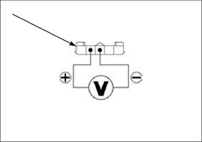
TP Sensor Power Input Voltage Inspection Connect the ECM 33P (Black) connector. Disconnect the sensor unit 5P connector [1]. Turn the ignition switch ON and engine stop switch " Measure the voltage at the sensor unit 5P connector of the wire side. Connection: Yellow/red (+) – Green/white (–) Standard: 4.75 – 5.25 V
Is the voltage within 4.75 – 5.25 V?
Y G/W
[1]
[1]
Y/R G/W
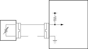
DTC 9 (IAT SENSOR)
5 V
SENSOR UNIT
(IAT SENSOR)
G/W
Probable cause • Open or short circuit in Gray/blue wire between the sensor unit and ECM
• Open circuit in Green/white wire between the sensor unit and ECM
• Faulty sensor unit • Faulty ECM
4-17 PGM-FI SYSTEM
DTC 9-1 (IAT SENSOR LOW VOLTAGE)
IAT Sensor System Inspection Turn the ignition switch ON and engine stop switch " Check the IAT sensor with the HDS pocket tester.
Is about 0 V indicated?
YES – GO TO STEP 2.
NO – Intermittent failure
IAT Sensor Inspection Turn the ignition switch OFF. Disconnect the sensor unit 5P connector. Turn the ignition switch ON and engine stop switch " Check the IAT sensor with the HDS pocket tester.
Is about 0 V indicated?
YES – GO TO STEP 3.
NO – Faulty sensor unit (IAT sensor)
IAT Sensor Voltage Input Line Short Circuit Inspection
DTC 9-2 (IAT SENSOR HIGH VOLTAGE)
IAT Sensor System Inspection Turn the ignition switch ON and engine stop switch "
Check the IAT sensor with the HDS pocket tester.
Is about 5 V indicated?
YES – GO TO STEP 2.
NO – • Intermittent failure • Loose or poor contact on the sensor unit 5P connector
|
|||||||||||||||||||||||||||||||||||||||||||||||||||||||||||||||||||||||||||||||||||||||||||||||||||||||||||||||||||||||||||||||
|
|
Последнее изменение этой страницы: 2016-04-08; просмотров: 373; Нарушение авторского права страницы; Мы поможем в написании вашей работы! infopedia.su Все материалы представленные на сайте исключительно с целью ознакомления читателями и не преследуют коммерческих целей или нарушение авторских прав. Обратная связь - 3.137.189.236 (0.005 с.) |

 ".
".

 Disconnect the sensor unit 5P connector [1].