Заглавная страница Избранные статьи Случайная статья Познавательные статьи Новые добавления Обратная связь FAQ Написать работу КАТЕГОРИИ: ТОП 10 на сайте Приготовление дезинфицирующих растворов различной концентрацииТехника нижней прямой подачи мяча. Франко-прусская война (причины и последствия) Организация работы процедурного кабинета Смысловое и механическое запоминание, их место и роль в усвоении знаний Коммуникативные барьеры и пути их преодоления Обработка изделий медицинского назначения многократного применения Образцы текста публицистического стиля Четыре типа изменения баланса Задачи с ответами для Всероссийской олимпиады по праву 
Мы поможем в написании ваших работ! ЗНАЕТЕ ЛИ ВЫ?
Влияние общества на человека
Приготовление дезинфицирующих растворов различной концентрации Практические работы по географии для 6 класса Организация работы процедурного кабинета Изменения в неживой природе осенью Уборка процедурного кабинета Сольфеджио. Все правила по сольфеджио Балочные системы. Определение реакций опор и моментов защемления |
Compression too low, hard starting or poor performance at low speedСодержание книги
Поиск на нашем сайте
• Leaking or damaged cylinder head gasket • Worn, stuck or broken piston rings • Worn or damaged cylinder and piston • Loose spark plug
Compression too high, overheating or knocking
• Excessive carbon built-up on piston or combustion chamber
Excessive smoke • Faulty cylinder, piston and piston rings • Improper installation of piston rings • Scored or scratched piston or cylinder wall
Abnormal noise (piston) • Worn piston pin or piston pin hole • Worn or damaged cylinder, piston or piston ring • Worn connecting rod small end
COMPONENT LOCATION
4.2 N·m (0.4 kgf·m, 3.1 lbf·ft)
11-2 CYLINDER/PISTON
CYLINDER/PISTON
CYLINDER REMOVAL
Remove the following:
– Water pipe (page 9-13) – Cylinder head (page 10-13)
Lift the cylinder [1] and remove it, being careful not to damage the piston with the stud bolts.
• Attach a piece of wire to the cam chain to prevent it from falling into the crankcase. • Do not tap the cylinder too hard and do not damage the mating surface with a screwdriver.
Remove the dowel pins [1] and gasket [2].
[1]
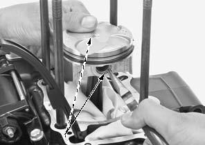
PISTON REMOVAL
Place a clean shop Remove the piston pin clips [1] with pliers. towel over the
crankcase to prevent the piston pin clips from falling into the crankcase.
[1]
11-3 CYLINDER/PISTON
• Do not damage the piston ring by spreading the ends too far.
• Be careful not to damage the piston when removing the piston ring.
INSPECTION
Inspect the following parts for scratch, damage, abnormal wear, deformation, burning or clogs in oil passages.
– Cylinder – Piston – Piston rings – Piston pin – Connecting rod small end
Measure each part and calculate the clearance according to CYLINDER/PISTON SPECIFICATIONS (page 1-6).
Replace any part if it is out of service limit.
STUD BOLT REPLACEMENT
Thread two nuts onto the stud bolt [1] and tighten them together, and use a wrench on them to turn the stud bolt out.
Install new stud bolts into the crankcase and tighten them to the specified torque.
TORQUE:9.0 N·m (0.9 kgf·m, 6.6 lbf·ft)
After installing the stud bolts, check that the length from the bolt head to the crankcase surface is within specification.
[1]
142.0 ± 1.0 mm
(5.6 ± 0.04 in)
11-4 CYLINDER/PISTON
PISTON INSTALLATION
Apply engine oil to the piston ring grooves. Apply engine oil to the piston ring entire surface.
Be careful not to Carefully install the piston rings into the piston ring damage the piston grooves with the markings [1] facing up.
and rings.
[2]
[1]
When cleaning the cylinder mating surface, place a shop towel over the cylinder opening to prevent dust or dirt enter the crankcase.
• Do not confuse the top ring [2] and second ring [3]. • To install the oil ring [4], install the spacer [5] first, then install the side rails [6].
Stagger the piston ring end gaps 120° apart from each other.
Stagger the side rail end gaps as shown.
Apply engine oil to the piston pin hole inner surface and sliding surface.
Clean any gasket material from the cylinder mating surface [1] of the crankcase.
Apply molybdenum oil solution to the connecting rod small end inner surfaces.
Apply molybdenum oil solution to the piston pin [1] outer surfaces.
Install the piston [2] with its "IN" mark [3] facing intake side.
Install the piston pin.
120° 120° 120°
[5]
[6]
[2]
[3]
[4]
20 mm (0.8 in) OR MORE
[1]
[3] [2]
11-5 CYLINDER/PISTON
Install new piston pin clips [1] into the grooves of the piston pin hole.
• Always use new piston pin clips. Reinstalling used piston pin clips may lead to serious engine damage. • Set the piston pin clip in the groove properly. • Do not align the clip’s end gap [2] with the piston cut-out [3].
CYLINDER INSTALLATION
Install the dowel pins [1] and a new gasket [2].
[2]
[3]
Be careful not to damage the piston rings and cylinder wall.
Apply engine oil to the cylinder [1] inner surface and piston [2] sliding surface.
Route the cam chain [3] through the cylinder and install the cylinder over the piston while compressing the piston rings with your fingers.
Install the following:
– Cylinder head (page 10-17) – Water pipe (page 9-13)
[1]
11-6 CYLINDER/PISTON
CAM CHAIN TENSIONER
REMOVAL/INSTALLATION
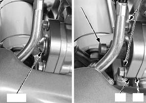
Remove the cam chain tensioner lifter plug [1] and O-ring [2].
Turn the cam chain tensioner lifter shaft fully in (clockwise) and secure it using the special tool.
Remove the cam chain tensioner lifter mounting bolts [4].
Remove the cam chain tensioner lifter [5] and gasket [6].
[1]/[2]
Install a new gasket [1] on the cam chain tensioner lifter [2] and install them to the cylinder.
[2]
TORQUE:4.2 N·m (0.4 kgf·m, 3.1 lbf·ft)
INSPECTION
Check the cam chain tensioner lifter [1] operation:
– The cam chain tensioner lifter shaft should not go into the cam chain tensioner lifter body when it is pushed.
– When it is turned clockwise with a tensioner stopper or a screwdriver [2], the cam chain tensioner lifter shaft should be pulled into the cam chain tensioner lifter body. The cam chain tensioner lifter shaft should spring out of the cam chain tensioner lifter body as soon as the stopper tool is released.
[5] [6]
[1]
[1]
[2]
11-7
CLUTCH/GEARSHIFT LINKAGE
SERVICE INFORMATION···························12-2 CLUTCH ······················································12-9
TROUBLESHOOTING·································12-2 GEARSHIFT LINKAGE·····························12-14
COMPONENT LOCATION··························12-3 PRIMARY DRIVE GEAR···························12-17
RIGHT CRANKCASE COVER ····················12-4
12-1 CLUTCH/GEARSHIFT LINKAGE
SERVICE INFORMATION
GENERAL
• This section covers service of the clutch and gearshift linkage. All services can be done with the engine installed in the frame. • Engine oil viscosity and level have an effect on clutch disengagement. Oil additives also effect clutch performance and are not recommended. When the clutch does not disengage or the motorcycle creeps with the clutch lever pulled in, inspect the engine oil level before servicing the clutch system.
TROUBLESHOOTING
Faulty clutch operation can usually be corrected by adjusting the freeplay.
|
||||||||||||||||||||||||||||||||||||||||||||||||||||||||||||||||||||||||||||||||||||||||||||||||||||||||||
|
|
Последнее изменение этой страницы: 2016-04-08; просмотров: 397; Нарушение авторского права страницы; Мы поможем в написании вашей работы! infopedia.su Все материалы представленные на сайте исключительно с целью ознакомления читателями и не преследуют коммерческих целей или нарушение авторских прав. Обратная связь - 3.145.103.119 (0.009 с.) |


 [1]
[1]
 [3]
[3] 


 [1]
[1]


 [3]
[3]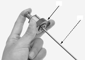
 MEMO
MEMO