Заглавная страница Избранные статьи Случайная статья Познавательные статьи Новые добавления Обратная связь FAQ Написать работу КАТЕГОРИИ: ТОП 10 на сайте Приготовление дезинфицирующих растворов различной концентрацииТехника нижней прямой подачи мяча. Франко-прусская война (причины и последствия) Организация работы процедурного кабинета Смысловое и механическое запоминание, их место и роль в усвоении знаний Коммуникативные барьеры и пути их преодоления Обработка изделий медицинского назначения многократного применения Образцы текста публицистического стиля Четыре типа изменения баланса Задачи с ответами для Всероссийской олимпиады по праву 
Мы поможем в написании ваших работ! ЗНАЕТЕ ЛИ ВЫ?
Влияние общества на человека
Приготовление дезинфицирующих растворов различной концентрации Практические работы по географии для 6 класса Организация работы процедурного кабинета Изменения в неживой природе осенью Уборка процедурного кабинета Сольфеджио. Все правила по сольфеджио Балочные системы. Определение реакций опор и моментов защемления |
Radiator cap/system pressure InspectionСодержание книги
Поиск на нашем сайте
Loosen the cap screw [1] and remove the radiator cap [2].
Wet the sealing surfaces of the radiator cap [1], then install the cap onto the tester [2].
Pressurize the cap using the tester. Replace the radiator cap if it does not hold pressure, or if relief pressure is too high or too low. It must hold the specified pressure for at least 6 seconds.
RADIATOR CAP RELIEF PRESSURE:
KPa (0.95 – 1.25 kgf/cm2, 13.5 – 17.8 psi)
Pressurize the radiator, engine and hoses using the tester, and check for leaks.
[2]
[1]
[1]
[2]
Excessive pressure can damage the cooling system
components. Do not exceed 122.6 kPa (1.25 kgf/cm2, 17.8 psi).
Repair or replace components if the system will not hold the specified pressure for at least 6 seconds.
Remove the tester.
Install the radiator cap and tighten the screw.
9-4 COOLING SYSTEM
COOLANT REPLACEMENT
When filling the system or reserve tank with a coolant (checking coolant level), support the
motorcycle on a level surface.
REPLACEMENT/AIR BLEEDING
Remove the radiator cap (page 9-4).
Remove the drain bolt [1] and sealing washer [2] on the water pump cover and drain the coolant from the system.
Install and tighten the drain bolt with a new sealing washer.
Fill the system with the recommended coolant through the filler opening.
RECOMMENDED ANTIFREEZE:
High quality ethylene glycol antifreeze containing silicate-free corrosion inhibitors
STANDARD COOLANT CONCENTRATION: 1:1 (mixture with distilled water)
Bleed air from the system as follows:
1. Shift the transmission into neutral.
Start the engine and let it idle for 2 – 3 minutes.
2. Snap the throttle 3 – 4 times to bleed air from the system.
3. Stop the engine and add the coolant.
4. Install the radiator cap and tighten the cap screw.
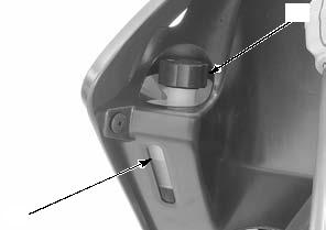
Remove the reserve tank cap [1] and fill the reserve tank to the "UPPER" level line [2].
Install the reserve tank cap.
[1]
[2]
[2]
[1]
THERMOSTAT
REMOVAL/INSTALLATION
Drain the coolant (page 9-5).
Remove the bolts [1] and thermostat cover [2].
[1]
[2]
9-5 COOLING SYSTEM
Remove the thermostat [1] from the cylinder head. Installation is in the reverse order of removal.
Wear insulated gloves and adequate eye protection. Keep flammable materials away from the electric heating element. Do not let the thermostat or thermometer touch the pan, or you will get false reading.
• Install the thermostat with the bleed hole [2] facing up.
• When installing the thermostat, align the tab of the seal ring [3] with the groove of the thermostat cover.
Fill and bleed the cooling system (page 9-5).
INSPECTION
Visually inspect the thermostat [1] for damage.
Check the seal ring [2] for damage and replace if necessary.
Heat the water with an electric heating element to operating temperature for 5 minutes.
Suspend the thermostat [1] in heated water to check its operation.
THERMOSTAT BEGIN TO OPEN: 81 – 84°C (178 – 183°F)
VALVE LIFT:
4.5 mm (0.18 in) minimum at 95°C (203°F)
Replace the thermostat if the valve open at a temperatures other than those specified.
[1]
[2]
[1]
RADIATOR/COOLING FAN
REMOVAL/INSTALLATION
Drain the coolant (page 9-5).
Remove the left fuel tank shroud (page 2-4).
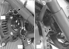
Release the spark plug wire [1] and radiator siphon hose [2] from the guides [3].
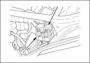
Disconnect the fan motor 2P (Black) connector [4].
[3]
[2]
[1] [4]
9-6 COOLING SYSTEM
Remove the radiator guard [4] by releasing the bosses [5]
Remove the radiator mounting bolts [6] and radiator [7].
[6]
Installation is in the reverse order of removal. Tighten the hose band screw to the specified range.
Fill the system with the recommended coolant (page 9-5).
0 – 1 mm (0 – 0.04 in)
DISASSEMBLY/ASSEMBLY
Disassemble and assemble the radiator as following illustration.
FAN MOTOR RADIATOR CAP
2.7 N·m (0.3 kgf·m, 2.0 lbf·ft)
RADIATOR
FAN MOTOR SHROUD
Align
1.0 N·m (0.1 kgf·m, 0.7 lbf·ft)
9-7 COOLING SYSTEM
WATER PUMP
MECHANICAL SEAL INSPECTION
Check the bleed hole [1] of the water pump for signs of coolant leakage.
If water leaks through the bleed hole, replace the mechanical seal (page 9-9).
If oil leaks through the bleed hole, replace the oil seal (page 9-9).
Make sure that there are no continuous coolant leakage from the bleed hole while operating the engine.
A small amount of weeping from the bleed hole is normal.
[2]
9-8 COOLING SYSTEM
BEARING/MECHANICAL SEAL/OIL SEAL REPLACEMENT
BEARINGS
MECHANICAL SEAL
[3] [1]
9-9 COOLING SYSTEM
Drive in a new bearing squarely with the marking side facing up.
Remove the mechanical seal [1] and oil seal [2] from the right crankcase cover.
[1]
Apply grease to a new oil seal [1] lips.
Install the oil seal to the right crankcase cover as shown.
Drive in new bearings [1] into the right crankcase cover using the special tools as shown.
After installing the bearing, lubricate it with engine oil.
Press a new mechanical seal [1] until it is fully seated to the right crankcase cover using the hydraulic press and special tool.
TOOL:
[2] Oil seal driver, 30 x 36 mm 07HMF-KR10101
[2]
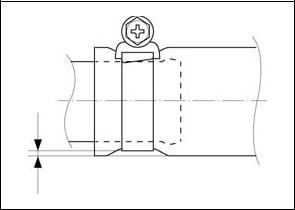
0 – 0.5 mm (0 – 0.02 in)
[2]
[2]
9-10 COOLING SYSTEM
INSTALLATION
Apply engine oil to the water pump shaft [1] outer surface.
Install the water pump shaft to the right crankcase cover.
Install the plain washer [1] and impeller [2] to the water pump shaft.
Hold the water pump shaft and tighten the water pump impeller [1] to the specified torque.
TORQUE:10 N·m (1.0 kgf·m, 7 lbf·ft)
Install the right crankcase cover (page 12-8).
Install a new O-ring [1] to the water pump cover [2]. Install the water pump cover.
[1]
[1]
[2]
9-11 COOLING SYSTEM
Install and tighten the bolts [1], drain bolt [2] and a new sealing washer [3] securely.
Fill the recommended coolant and bleed the air (page 9-5).
[1]
RADIATOR RESERVE TANK
REMOVAL/INSTALLATION
Remove the right fuel tank shroud (page 2-4).
Place an approved container under the radiator reserve tank [1].
Disconnect the overflow hose [2] and siphon hose [3] from the reserve tank.
Remove the bolts [4] and radiator reserve tank Installation is in the reverse order of removal. Fill the reserve tank with coolant (page 9-5).
[2]
[4]
[3]
[2]
FAN CONTROL RELAY
INSPECTION
Remove the left side cover (page 2-3).
Remove the dust cover [1] Remove the fan control relay [2].
Connect a ohmmeter to the fan control relay [1] terminals.
Connect a 12 V battery to the fan control relay terminals as shown.
There should be continuity only when 12 V battery is connected.
If there is no continuity when the 12 V battery is connected, replace the fan control relay.
[2]
[1]
[1]
9-12 COOLING SYSTEM
WATER PIPE
REMOVAL/INSTALLATION
9-13
CYLINDER HEAD/VALVES
10-1 CYLINDER HEAD/VALVES
SERVICE INFORMATION
GENERAL
• This section covers service of the cylinder head, valves, rocker arms and camshaft. • The camshaft and rocker arm service can be done with the engine installed in the frame. The cylinder head service requires engine removal.
• Be careful not to damage the mating surfaces when removing the cylinder head cover and cylinder head. Do not tap the cylinder head cover and cylinder head too hard during removal. • When disassembling, mark and store the disassembled parts to ensure that they are reinstalled in their original locations. • Clean all disassembled parts with cleaning solvent and dry them by blowing them off with compressed air before inspection. • Camshaft and rocker arm lubricating oil is fed through oil passage in the cylinder head (stud bolt hole) and camshaft holder. Clean the oil passage before assembling them.
TROUBLESHOOTING
• Engine top-end problems usually affect engine performance. These problems can be diagnosed by a compression test, or by tracing top-end noise with a sounding rod or stethoscope.
• If the performance is poor at low speeds, check for white smoke in the crankcase breather hose. If the hose is smoky, check for a seized piston rings.
|
||||||||||||||||||||||||||||||||||||||||||||||||||||||||||||||||||||||||||||||||||||||||||||||||||||||||||||||||||||||||||||||||||||||||||||||||||||||||||||||||||||||||||||||||||||||||||||||||||||||||||||||||||||||||||||||||||||||||||||||||||||||||||||||||||||||||||||||||||||||||||||||||||||||||||||||||||||||||||||||||||||||
|
|
Последнее изменение этой страницы: 2016-04-08; просмотров: 456; Нарушение авторского права страницы; Мы поможем в написании вашей работы! infopedia.su Все материалы представленные на сайте исключительно с целью ознакомления читателями и не преследуют коммерческих целей или нарушение авторских прав. Обратная связь - 216.73.216.57 (0.011 с.) |


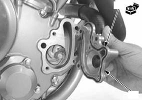
 Remove the bolts [1], drain bolt [2], sealing washer [3], water pump cover [4] and O-ring [5].


 OIL
OIL  SEAL
SEAL


 [1]
[1]
 [1]
[1] 


 [1]
[1]
 [3]/[4]


 MEMO
MEMO