Заглавная страница Избранные статьи Случайная статья Познавательные статьи Новые добавления Обратная связь FAQ Написать работу КАТЕГОРИИ: ТОП 10 на сайте Приготовление дезинфицирующих растворов различной концентрацииТехника нижней прямой подачи мяча. Франко-прусская война (причины и последствия) Организация работы процедурного кабинета Смысловое и механическое запоминание, их место и роль в усвоении знаний Коммуникативные барьеры и пути их преодоления Обработка изделий медицинского назначения многократного применения Образцы текста публицистического стиля Четыре типа изменения баланса Задачи с ответами для Всероссийской олимпиады по праву 
Мы поможем в написании ваших работ! ЗНАЕТЕ ЛИ ВЫ?
Влияние общества на человека
Приготовление дезинфицирующих растворов различной концентрации Практические работы по географии для 6 класса Организация работы процедурного кабинета Изменения в неживой природе осенью Уборка процедурного кабинета Сольфеджио. Все правила по сольфеджио Балочные системы. Определение реакций опор и моментов защемления |
Service Limit: 32.6 mm (1.28 in.)Содержание книги
Поиск на нашем сайте
• Visually inspect the clutch housing fingers [A] where the friction plate tangs [B] hit them.
• Visually inspect where the teeth [A] on the steel plates wear against the clutch hub splines [B].
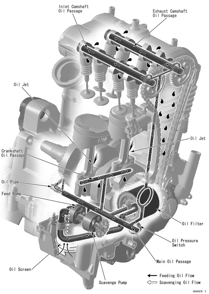
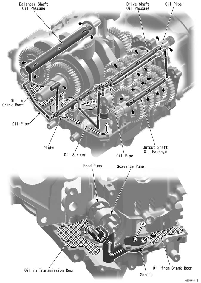
Engine Lubrication System Table of Contents Exploded View........................................................................................................................ 7-2 Engine Oil Flow Chart............................................................................................................. 7-4 Specifications......................................................................................................................... 7-6 Special Tools and Sealant...................................................................................................... 7-7 Engine Oil and Oil Filter.......................................................................................................... 7-8 Oil Level Inspection........................................................................................................... 7-8 Engine Oil Change............................................................................................................ 7-8 Oil Filter Replacement...................................................................................................... 7-8 Oil Pan.................................................................................................................................... 7-9 Oil Pan Removal............................................................................................................... 7-9 Oil Pan Installation............................................................................................................ 7-10 Oil Pressure Relief Valve Removal................................................................................... 7-11 Oil Pressure Relief Valve Installation................................................................................ 7-11 Oil Pressure Relief Valve Inspection................................................................................. 7-11 Oil Pump................................................................................................................................. 7-12 Oil Pump Removal............................................................................................................ 7-12 Oil Pump Installation......................................................................................................... 7-13 Oil Pressure Measurement..................................................................................................... 7-14 Oil Pressure Measurement............................................................................................... 7-14 Oil Pressure Switch................................................................................................................ 7-15 Oil Pressure Switch Removal........................................................................................... 7-15 Oil Pressure Switch Installation........................................................................................ 7-15
EO: Apply engine oil. G: Apply grease. L: Apply a non-permanent locking agent. Lh: Left-hand threads MO: Apply molybdenum disulfide oil solution. (mixture of the engine oil and molybdenum disulfide grease in a weight ratio 10: 1) R: Replacement Parts SS: Apply silicone sealant.
Oil Filter Wrench: 57001-1249
Kawasaki Bond (Silicone Sealant): 56019-120
• Check that the engine oil level is between the upper [A] and lower [B] levels in the gauge. NOTE ○Situate the motorcycle so that it is perpendicular to the ground. ○If the motorcycle has just been used, wait several min- utes for all the oil to drain down. ○If the oil has just been changed, start the engine and run it for several minutes at idle speed. This fills the oil filter with oil. Stop the engine, then wait several minutes until the oil settles.
If the oil level is too high, remove the excess oil, using a syring or some other suitable device.
NOTE ○If the engine oil type and make are unknown, use any brand of the specified oil to top off the level in preference to running the engine with the oil level low. Then at your earliest convenience, change the oil completely. Engine Oil Change • Refer to the Engine Oil Change in the Periodic Mainte- nance chapter. Oil Filter Replacement • Refer to the Oil Filter Replacement in the Periodic Main- tenance chapter.
Oil Pan Removal
Engine Oil (Drain, see Engine Oil Change in the Periodic Maintenance chapter) Exhaust Pipe (see Exhaust Pipe Removal in the Engine Top End chapter) Muffler Body (see Muffler Body Removal in the Engine Top End chapter) Oil Pan Bolts [A] Oil Pan [B] Gasket [C] Damper [D]
Filter Plate [B] Filter [C]
Oil Screen [A] Oil Pipe Plate Bolt [B] Oil Pipe Plate [C] Oil Pipes [D] Oil Pressure Relief Valve [E]
Oil Pan Installation
• Install the oil pipe plate [B] so that its guide portion [C] fits the breather pipe [D] as shown. • Apply a non-permanent locking agent to the oil pipe plate bolt. Torque - Oil Pipe Plate Bolt [E]: 9.8 N·m (1.0 kgf·m, 87 in·lb)
○Apply a non-permanent locking agent to the threads [G]
of the oil pressure relief valve, and tighten it. Torque - Oil Pressure Relief Valve: 15 N·m (1.5 kgf·m, 11 ft·lb)
• Be sure the damper [C] is on the end of the breather pipe [D].
• When installing the oil pan, align [A] the damper [B] on the breather pipe with the hollow [C] on the oil pan. • Tighten: Torque - Oil Pan Bolts: 12 N·m (1.2 kgf·m, 106 in·lb)
Oil Pressure Relief Valve Removal • Refer to the Oil Pan Removal. Oil Pressure Relief Valve Installation
Oil Pressure Relief Valve Inspection • Check to see if the valve [A] slides smoothly when push- ing it in with a wooden or other soft rod, and see if it comes back to its seat by spring [B] pressure. NOTE ○Inspect the valve in its assembled state. Disassembly and assembly may change the valve performance.
 If any rough spots are found during above inspection, wash the valve clean with a high-flash point solvent and blow out any foreign particles that may be in the valve with compressed air. If any rough spots are found during above inspection, wash the valve clean with a high-flash point solvent and blow out any foreign particles that may be in the valve with compressed air.
If cleaning does not solve the problem, replace the oil pressure relief valve as an assembly. The oil pressure relief valve is precision made with no allowance for re- placement of individual parts.
Oil Pump Removal
Engine Oil (see Engine Oil Change in the Periodic Main- tenance chapter) • Remove: Clutch (see Clutch Removal in the Clutch chapter) Oil Pump Cover Bolts [A] Oil Pump Cover [B]
Inner Rotor [A] for Scavenge Pump Outer Rotor [B] for Scavenge Pump
Pin [B] Oil Pump Body [C] with Oil Pump Shaft [D] and Pin
Inner Rotor [A] for Feed Pump Outer Rotor [B] for Feed Pump
Oil Pump Installation
• Install: Outer Rotor [B] for Feed Pump Inner Rotor [C] for Feed Pump Oil Pump Shaft [D] and Pin [E] Dowel Pin [F] Oil Pump Body [G] Pin [H] and Inner Rotor [I] for Scavenge Pump Outer Rotor [J] for Scavenge Pump Oil Pump Cover [K] NOTE ○Thescavenge pump rotors are wider than the feed pump rotors. • Apply a non-permanent locking agent to the oil pump cover bolts and tighten them. Torque - Oil Pump Cover Bolts: 9.8 N·m (1.0 kgf·m, 87 in·lb)
Oil Pressure Measurement
• Remove the oil passage plug, and attach the adapter [A] and gauge [B] to the plug hole. Special Tools - Oil Pressure Gauge, 10 kgf/cm²: 57001-164 Oil Pressure Gauge Adapter, PT3/8: 57001 -1233 • Start the engine and warm up the engine. • Run the engine at the specified speed, and read the oil pressure gauge.
Oil Pressure Standard: 216 ~ 294 kPa (2.2 ~ 3.0 kgf/cm², 31 ~ 43 psi) at 4 000 r/min (rpm), oil temperature. 90°C (194°F) • Stop the engine.
• Apply a non-permanent locking agent to the oil passage plug, and install it. Torque - Oil Passage Plug: 20 N·m (2.0 kgf·m, 15 ft·lb)
Oil Pressure Switch Removal
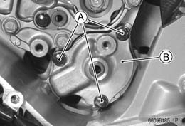
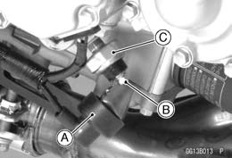
Engine Oil (Drain, see Engine Oil Change in the Periodic Maintenance chapter) Right Lower Fairing (see Lower Fairing Removal in the Frame chapter) Switch Cover [A] Switch Terminal Bolt [B] Oil Pressure Switch [C]
• Apply silicone sealant to the threads of the oil pressure switch and tighten it.
|
||||||||||||||||||||||||||||||||||||||||||||||||||||||||||||||||||||||||||||||||||||||||||||||||||||||||||||||||||||||||||||||
|
|
Последнее изменение этой страницы: 2016-08-10; просмотров: 354; Нарушение авторского права страницы; Мы поможем в написании вашей работы! infopedia.su Все материалы представленные на сайте исключительно с целью ознакомления читателями и не преследуют коммерческих целей или нарушение авторских прав. Обратная связь - 3.133.136.95 (0.007 с.) |

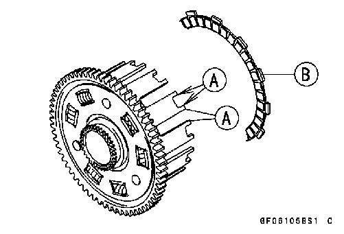 Clutch Housing Finger Inspection
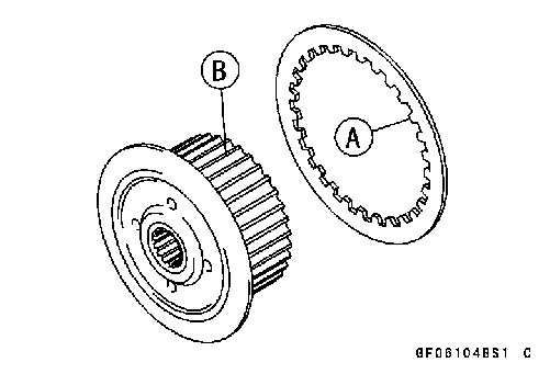 Clutch Housing Spline Inspection
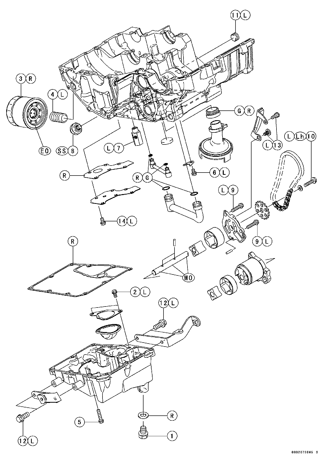

 Oil Pressure Gauge, 10 kgf/cm²: 57001-164
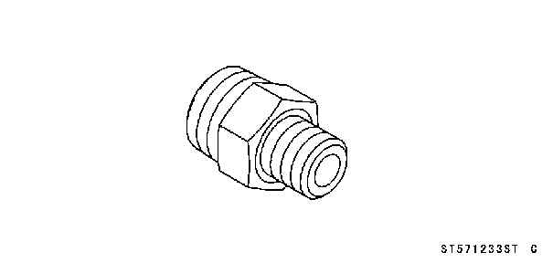
 Oil Pressure Gauge Adapter, PT3/8: 57001-1233
 Oil Level Inspection
 • Remove:
 • Remove the following from the oil pan as necessary. Filter Plate Bolts [A]
 • Remove the following from the lower crankcase half as necessary.
 • Apply grease to the O-rings on the oil pipes [A].
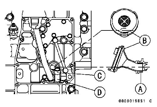 • Apply grease to the O-ring [A] on the oil screen [B] and install it on the lower crankcase half as shown.
 • Replace the oil pan gasket with a new one.
 • Refer to the Oil Pan Installation.
 • Drain:
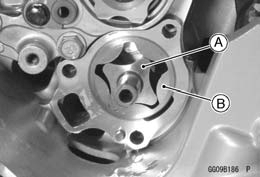 • Remove:
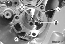 • Remove: Dowel Pin [A]
 • Remove:
 • Apply molybdenum disulfide grease to the portion [A] of the oil pump shaft as shown.
 • Remove the right lower fairing (see Lower Fairing Re- moval in the Frame chapter).
 • Remove:
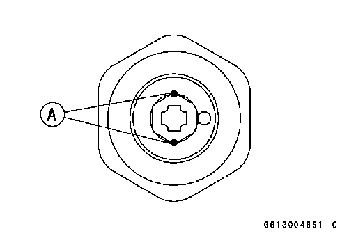 Oil Pressure Switch Installation