Заглавная страница Избранные статьи Случайная статья Познавательные статьи Новые добавления Обратная связь FAQ Написать работу КАТЕГОРИИ: ТОП 10 на сайте Приготовление дезинфицирующих растворов различной концентрацииТехника нижней прямой подачи мяча. Франко-прусская война (причины и последствия) Организация работы процедурного кабинета Смысловое и механическое запоминание, их место и роль в усвоении знаний Коммуникативные барьеры и пути их преодоления Обработка изделий медицинского назначения многократного применения Образцы текста публицистического стиля Четыре типа изменения баланса Задачи с ответами для Всероссийской олимпиады по праву 
Мы поможем в написании ваших работ! ЗНАЕТЕ ЛИ ВЫ?
Влияние общества на человека
Приготовление дезинфицирующих растворов различной концентрации Практические работы по географии для 6 класса Организация работы процедурного кабинета Изменения в неживой природе осенью Уборка процедурного кабинета Сольфеджио. Все правила по сольфеджио Балочные системы. Определение реакций опор и моментов защемления |
Sealant - Kawasaki Bond (Silicone Sealant): 56019-120Содержание книги
Поиск на нашем сайте
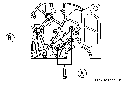
Torque - Oil Pressure Switch: 15 N·m (1.5 kgf·m, 11 ft·lb) • Tighten the terminal bolt securely. • Apply a small amount grease to the terminal so that grease should not close two breather holes [A] for switch diaphragm.
Engine Removal/Installation Table of Contents Exploded View........................................................................................................................ 8-2 Engine Removal/Installation................................................................................................... 8-4 Engine Removal................................................................................................................ 8-4 Engine Installation............................................................................................................. 8-7
8
4. Engine Mounting Brackets 5. Collar S: Follow the specified tightening sequence.
Engine Removal
• Squeeze the brake lever slowly and hold it with a band
[A].
• Drain: Engine Oil (see Engine Oil Change in the Periodic Main- tenance chapter) Coolant (see Coolant Change in the Periodic Mainte- nance chapter) • Remove: Seat (see Seat Removal in the Frame chapter) Lower Fairings (see Lower Fairing Removal in the Frame chapter) Upper Inner Fairings (see Upper Inner Fairing Removal in the Frame chapter) Windshield (see Windshield Removal in the Frame chapter) Meter Cover (see Meter Unit Removal/Installation in the Electrical System chapter) Center Fairings (see Center Fairing Removal in the Frame chapter) Side Covers (see Side Cover Removal in the Frame chapter) Frame Covers (see Frame Cover Removal in the Frame chapter) Radiator and Hoses (see Radiator and Radiator Fan Re- moval in the Cooling System chapter)
• Unscrew the lower fairing bracket bolts (both sides) [B] and remove the brackets (both sides) [C]. • Disconnect the oil pressure switch terminal [D].
• Disconnect the crankshaft sensor lead connector [A].
Exhaust Pipe (see Exhaust Pipe Removal in the Engine Top End chapter) Muffler Body (see Muffler Body Removal in the Engine Top End chapter) Fuel Tank (see Fuel Tank Removal in the Fuel System (DFI) chapter) Air Switching Valve and Hose (see Air Switching Valve Removal in the Engine Top End chapter) Air Cleaner Housing (see Air Cleaner Housing Removal in the Fuel System (DFI) chapter) Throttle Body Assy (see Throttle Body Assy Removal in the Fuel System (DFI) chapter) Clutch Cable (see Clutch Cable Removal in the Clutch chapter)
Stick Coils [A] Baffle Plate [B] Hose [C]
Water Temperature Sensor Lead Connector [A] Starter Motor Cable [B] Engine Ground Cable Terminal Bolt [C] Alternator Lead Connector [D] Sidestand Switch Lead Connector [E] Speed Sensor Lead Connector [F]
• Remove the shift pedal [A] (see Shift Pedal Removal in the Crankshaft/Transmission chapter). • Disconnect: Oxygen Sensor Lead Connector [B] (Europe Models) Neutral Switch Lead Terminal [C] • Remove the bracket [D] and the engine sprocket [E] (see Engine Sprocket Removal in the Final Drive chapter).
○Put a wooden board [B] on the suitable stand. • Remove the engine mounting bolts [C]. • Remove the engine mounting bracket bolts (both sides) [D] and remove the brackets [E]. • Remove the engine [F].
• Firstly, insert the rear engine mounting bolts [A] from the left side of the engine. • Secondly, temporally tighten the right engine mounting bracket bolts [B] and then the right front engine mounting bolt [C]. ○Position the collar [D] as shown. • Thirdly, temporally tighten the left engine mounting bracket bolts [E] and then the left front engine mounting bolt [F]. • Fourthly, temporally tighten the rear engine mounting nuts [G]. • Fifthly, tighten the rear engine mounting nuts. Torque - Rear Engine Mounting Nuts: 44 N·m (4.5 kgf·m, 32 ft·lb) • Sixthly, tighten the right engine mounting bracket bolts. Torque - Engine Mounting Bracket Bolts: 25 N·m (2.5 kgf·m, 18 ft·lb) • Seventhly, tighten the right front engine mounting bolt. Torque - Front Engine Mounting Bolt: 44 N·m (4.5 kgf·m, 32 ft·lb) • Eighthly, tighten the left engine mounting bracket bolts. Torque - Engine Mounting Bracket Bolts: 25 N·m (2.5 kgf·m, 18 ft·lb) • Lastly, tighten the left front engine mounting bolt. Torque - Front Engine Mounting Bolt: 44 N·m (4.5 kgf·m, 32 ft·lb) • Install the engine sprocket (see Engine Sprocket Installa- tion in the Final Drive chapter). • Run the leads, cables, and hoses correctly (see Cable, Wire, and Hose Routing section in the Appendix chapter). • Install the removed parts (see appropriate chapters). • Adjust: Throttle Cables (see Throttle Control System Inspection in the Periodic Maintenance chapter) Clutch Cable (see Clutch Operation Inspection in the Pe- riodic Maintenance chapter) Drive Chain (see Drive Chain Slack Adjustment in the Periodic Maintenance chapter) • Fill the engine with engine oil (see Engine Oil Change in the Periodic Maintenance chapter). • Fill the engine with coolant and bleed the air from the cool- ing system (see Coolant Change in the Periodic Mainte- nance chapter). • Adjust the idling (see Idle Speed Adjustment in the Peri- odic Maintenance chapter).
Crankshaft/Transmission Table of Contents Exploded View........................................................................................................................ 9-2 Specifications......................................................................................................................... 9-6 Special Tools and Sealant...................................................................................................... 9-9 Crankcase Splitting................................................................................................................. 9-10 Crankcase Splitting........................................................................................................... 9-10 Crankcase Assembly........................................................................................................ 9-11 Crankshaft and Connecting Rods........................................................................................... 9-17 Crankshaft Removal......................................................................................................... 9-17 Crankshaft Installation...................................................................................................... 9-17 Connecting Rod Removal................................................................................................. 9-17 Connecting Rod Installation.............................................................................................. 9-18 Crankshaft/Connecting Rod Cleaning............................................................................... 9-21 Connecting Rod Bend....................................................................................................... 9-21 Connecting Rod Twist....................................................................................................... 9-22 Connecting Rod Big End Side Clearance......................................................................... 9-22 Connecting Rod Big End Bearing Insert/Crankpin Wear.................................................. 9-22 Crankshaft Runout............................................................................................................ 9-24 Crankshaft Main Bearing Insert/Journal Wear.................................................................. 9-24 Balancer................................................................................................................................. 9-27 Balancer Removal............................................................................................................. 9-27 Balancer Installation.......................................................................................................... 9-27 Balancer Shaft Bearing Insert/Journal Clearance............................................................. 9-27 Transmission.......................................................................................................................... 9-29 Shift Pedal Removal......................................................................................................... 9-29 Shift Pedal Installation...................................................................................................... 9-29 External Shift Mechanism Removal.................................................................................. 9-29 External Shift Mechanism Installation............................................................................... 9-30 External Shift Mechanism Inspection................................................................................ 9-31 Transmission Assy Removal............................................................................................. 9-32 Transmission Assy Disassembly...................................................................................... 9-33 Transmission Assy Assembly........................................................................................... 9-33 Transmission Assy Installation.......................................................................................... 9-34 Transmission Shaft Removal............................................................................................ 9-35 Transmission Shaft Installation......................................................................................... 9-35 Transmission Shaft Disassembly...................................................................................... 9-36 Transmission Shaft Assembly........................................................................................... 9-36 Shift Drum and Fork Removal........................................................................................... 9-39 Shift Drum and Fork Installation........................................................................................ 9-39 Shift Drum Disassembly.................................................................................................... 9-39 Shift Drum Assembly........................................................................................................ 9-39 Shift Fork Bending............................................................................................................ 9-39 Shift Fork/Gear Groove Wear........................................................................................... 9-39 Shift Fork Guide Pin/Drum Groove Wear.......................................................................... 9-40 Gear Dog and Gear Dog Hole Damage............................................................................ 9-40 Ball Bearing, Needle Bearing, and Oil Seal............................................................................ 9-41 Ball and Needle Bearing Replacement............................................................................. 9-41 Ball and Needle Bearing Wear.......................................................................................... 9-41 Oil Seal Inspection............................................................................................................ 9-41
15. Do not apply any grease or oil. G: Apply grease. L: Apply a non-permanent locking agent. LG: Apply liquid gasket. M: Apply molybdenum disulfide grease. MO: Apply molybdenum disulfide oil solution. (mixture of the engine oil and molybdenum disulfide grease in a weight ratio 10: 1) R: Replacement Parts S: Follow the specified tightening sequence. SS: Apply silicone sealant.
EO: Apply engine oil. G: Apply grease. L: Apply a non-permanent locking agent. MO: Apply molybdenum disulfide oil solution. (mixture of the engine oil and molybdenum disulfide grease in a weight ratio 10: 1) R: Replacement Parts
Kawasaki Bond: 92104-1064
Crankcase Splitting • Remove: Engine (see Engine Removal in the Engine Removal/In- stallation chapter) Cylinder (see Cylinder Removal in the Engine Top End chapter) Pistons (see Piston Removal in the Engine Top End chapter) Stater Motor (see Starter Motor Removal in the Electrical System chapter) Clutch (see Clutch Removal in the Clutch chapter) Transmission Assy (see Transmission Assy Removal) Alternator Rotor (see Alternator Rotor Removal in the Electrical System chapter)
chapter). • Remove the lower crankcase bolts. ○Firstly loosen the M6 bolts, secondly the M8 bolts and lastly the M9 bolts. M6 Bolts [A] M8 Bolts [B] M9 Bolts [C] and Washers • Tap lightly around the crankcase mating surface with a plastic mallet, and split the crankcase. Take care not to damage the crankcase.
If the oil pipe is to be removed, follow the next procedure.
○Remove the oil pipe [B], tapping [C] the rod as shown.
○Remove the oil pipe (see above). ○Cut the gasket around the plate [B]. ○Remove: Breather Plate Bolts [C] Breather Plate with Pipe
Crankcase Assembly • With a high-flash point solvent, clean off the mating sur- faces of the crankcases halves and wipe dry. • Using compressed air, blow out the oil passages in the crankcase halves.
• Apply a non-permanent locking agent to the oil plate bolts and torque them. Torque - Oil Plate Bolts [B]: 9.8 N·m (1.0 N·m, 87 in·lb)
|
||||||||||||||||||||||||||||||||||||||||||||||||||||||||||||||||||||||||||||||||||||||||||||||||||||||||||||||||||||||||||||||||||||||||||||||||||||||||||||||||||||||||||||||||||||||||||||||||||||||||||||||||||||||||||||||||||||||||||||||||||||||||||||||||||||||||||||||||||||||||||||||||||||||||||||||||||||||||||||||||||||||||||||||||||||||||||||||||||||||||||||||||||||||||||||||||||||||||||||||||||||||||||||||||||||||||||||||||||||||||
|
|
Последнее изменение этой страницы: 2016-08-10; просмотров: 572; Нарушение авторского права страницы; Мы поможем в написании вашей работы! infopedia.su Все материалы представленные на сайте исключительно с целью ознакомления читателями и не преследуют коммерческих целей или нарушение авторских прав. Обратная связь - 18.188.218.219 (0.009 с.) |


 • Support the rear part of the swingarm with a stand.
 • Pull the clamp [A] on the lower fairing bracket.
 • Remove:
 • Remove:
 • Remove or Disconnect:
 • Remove the engine sprocket cover (see Engine Sprocket Removal in the Final Drive chapter).
 • Support the engine with a stand or jack [A].
 Engine Installation

 Outside Circlip Pliers: 57001-144
 Bearing Driver Set: 57001-1129
 • Remove the upper crankcase bolts [A] and the washers.
 • Remove the oil pan, relief valve, oil screen and oil pipes (see Oil Pan Removal in the Engine Lubrication System
 ○Unscrew the bolts [A] and remove the oil pipe [B].
 ○Preparea 5 mm rod [A], and insert it to the hole of the upper crankcase half.
 If the breather plate [A] is to be removed, follow the next procedure.
 • If the oil plate [A] on the upper crankcase half was re- moved, install it as shown.
 • Press and insert [A] the new needle bearing [B] for the shift drum until it is bottomed.