Заглавная страница Избранные статьи Случайная статья Познавательные статьи Новые добавления Обратная связь FAQ Написать работу КАТЕГОРИИ: ТОП 10 на сайте Приготовление дезинфицирующих растворов различной концентрацииТехника нижней прямой подачи мяча. Франко-прусская война (причины и последствия) Организация работы процедурного кабинета Смысловое и механическое запоминание, их место и роль в усвоении знаний Коммуникативные барьеры и пути их преодоления Обработка изделий медицинского назначения многократного применения Образцы текста публицистического стиля Четыре типа изменения баланса Задачи с ответами для Всероссийской олимпиады по праву 
Мы поможем в написании ваших работ! ЗНАЕТЕ ЛИ ВЫ?
Влияние общества на человека
Приготовление дезинфицирующих растворов различной концентрации Практические работы по географии для 6 класса Организация работы процедурного кабинета Изменения в неживой природе осенью Уборка процедурного кабинета Сольфеджио. Все правила по сольфеджио Балочные системы. Определение реакций опор и моментов защемления |
Owner’s Tool - Spark Plug Wrench, 16 mm: 92110-1132Содержание книги
Поиск на нашем сайте
Owner’s Tool - Spark Plug Wrench, 16 mm: 92110-1132 • Tighten: Torque - Spark Plugs: 15 N·m (1.5 kgf·m, 11 ft·lb) • Install: Stick Coils (see Stick Coil (Ignition Coil together with Spark Plug Cap) Installation in the Electrical System chapter)
Fuel System (DFI) Table of Contents Exploded View........................................................................................................................ 3-4 DFI System............................................................................................................................. 3-10 DFI System............................................................................................................................. 3-12 DFI Parts Location.................................................................................................................. 3-15 3 Specifications......................................................................................................................... 3-16 Special Tools and Sealant...................................................................................................... 3-18 DFI Servicing Precautions...................................................................................................... 3-20 DFI Servicing Precautions................................................................................................ 3-20 Troubleshooting the DFI System............................................................................................ 3-22 Outline................................................................................................................................. 3-22 Outline............................................................................................................................... 3-22 Inquiries to Rider.................................................................................................................. 3-26 Inquiries to Rider............................................................................................................... 3-26 DFI System Troubleshooting Guide....................................................................................... 3-29 Self-Diagnosis........................................................................................................................ 3-37 Self-diagnosis Outline.......................................................................................................... 3-37 Self-diagnosis Outline....................................................................................................... 3-37 Self-diagnosis Procedures................................................................................................... 3-37 Self-diagnosis Procedures................................................................................................ 3-37 Service Code Clearing Procedures..................................................................................... 3-38 Service Code Clearing Procedures................................................................................... 3-38 How to Read Service Codes................................................................................................ 3-40 How to Read Service Codes............................................................................................. 3-40 How to Erase Service Codes............................................................................................... 3-40 How to Erase Service Codes............................................................................................ 3-40 Service Code Table.............................................................................................................. 3-41 Service Code Table........................................................................................................... 3-41 Backups............................................................................................................................... 3-42 Backups............................................................................................................................ 3-42 Main Throttle Sensor (Service Code 11)................................................................................ 3-44 Main Throttle Sensor Removal/Adjustment...................................................................... 3-44 Main Throttle Sensor Input Voltage Inspection................................................................. 3-44 Main Throttle Sensor Output Voltage Inspection.............................................................. 3-45 Main Throttle Sensor Resistance Inspection.................................................................... 3-46 Inlet Air Pressure Sensor (Service Code 12).......................................................................... 3-47 Inlet Air Pressure Sensor Removal................................................................................... 3-47 Inlet Air Pressure Sensor Installation................................................................................ 3-47 Inlet Air Pressure Sensor Input Voltage Inspection........................................................... 3-47 Inlet Air Pressure Sensor Output Voltage Inspection........................................................ 3-48 Inlet Air Temperature Sensor (Service Code 13).................................................................... 3-52 Inlet Air Temperature Sensor Removal/Installation........................................................... 3-52 Inlet Air Temperature Sensor Output Voltage Inspection.................................................. 3-52 Inlet Air Temperature Sensor Resistance Inspection........................................................ 3-53 Water Temperature Sensor (Service Code 14)...................................................................... 3-54 Water Temperature Sensor Removal/Installation............................................................. 3-54 Water Temperature Sensor Output Voltage Inspection..................................................... 3-54 Water Temperature Sensor Resistance Inspection........................................................... 3-55 Crankshaft Sensor (Service Code 21).................................................................................... 3-56 Crankshaft Sensor Removal/Installation........................................................................... 3-56 Crankshaft Sensor Inspection........................................................................................... 3-56
Speed Sensor (Service Code 24, 25)..................................................................................... 3-57 Speed Sensor Removal/Installation.................................................................................. 3-57 Speed Sensor Inspection.................................................................................................. 3-57 Speed Sensor Input Voltage Inspection............................................................................ 3-57 Speed Sensor Output Voltage Inspection......................................................................... 3-57 Vehicle-down Sensor (Service Code 31)................................................................................ 3-59 Vehicle-down Sensor Removal......................................................................................... 3-59 Vehicle-down Sensor Installation...................................................................................... 3-59 Vehicle-down Sensor Inspection....................................................................................... 3-59 Subthrottle Sensor (Service Code 32).................................................................................... 3-62 Subthrottle Sensor Removal/Adjustment.......................................................................... 3-62 Subthrottle Sensor Input Voltage Inspection..................................................................... 3-62 Subthrottle Sensor Output Voltage Inspection.................................................................. 3-63 Subthrottle Sensor Resistance Inspection........................................................................ 3-64 Oxygen Sensor-not activated (Service Code 33) (Europe Models)........................................ 3-66 Oxygen Sensor Removal/Installation................................................................................ 3-66 Oxygen Sensor Inspection................................................................................................ 3-66 Stick Coils #1, #2: (Service Code 51, 52).............................................................................. 3-68 Stick Coil Removal/Installation.......................................................................................... 3-68 Stick Coil Input Voltage Inspection.................................................................................... 3-68 Radiator Fan Relay (Service Code 56)................................................................................... 3-70 Radiator Fan Relay Removal/Installation.......................................................................... 3-70 Radiator Fan Relay Inspection.......................................................................................... 3-70 Subthrottle Valve Actuator (Service Code 62)........................................................................ 3-71 Subthrottle Valve Actuator Removal................................................................................. 3-71 Subthrottle Valve Actuator Audible Inspection.................................................................. 3-71 Subthrottle Valve Actuator Inspection............................................................................... 3-71 Subthrottle Valve Actuator Resistance Inspection............................................................ 3-71 Subthrottle Valve Actuator Input Voltage Inspection......................................................... 3-72 Air Switching Valve (Service Code 64)................................................................................... 3-73 Air Switching Valve Removal/Installation.......................................................................... 3-73 Air Switching Valve Inspection.......................................................................................... 3-73 Oxygen Sensor Heater (Service Code 67) (Europe Models)................................................. 3-74 Oxygen Sensor Heater Removal/Installation.................................................................... 3-74 Oxygen Sensor Heater Inspection................................................................................... 3-74 Oxygen Sensor-Incorrect Output Voltage (Service Code 94) (Europe Models)..................... 3-76 Oxygen Sensor Removal/Installation................................................................................ 3-76 Oxygen Sensor Inspection................................................................................................ 3-76 FI Indicator Light (LED).......................................................................................................... 3-78 FI Indicator Light (LED) Inspection................................................................................... 3-79 ECU........................................................................................................................................ 3-80 ECU Removal................................................................................................................... 3-80 ECU Installation................................................................................................................ 3-80 ECU Power Supply Inspection.......................................................................................... 3-81 Fuel Line................................................................................................................................. 3-83 Fuel Pressure Inspection.................................................................................................. 3-83 Fuel Flow Rate Inspection................................................................................................ 3-85 Fuel Pump.............................................................................................................................. 3-87 Fuel Pump Removal......................................................................................................... 3-87 Fuel Pump Installation...................................................................................................... 3-87 Fuel Pump Operation Inspection...................................................................................... 3-88 Fuel Pump Operating Voltage Inspection......................................................................... 3-88 Pressure Regulator Removal............................................................................................ 3-89 Pump Screen, Fuel Filter Cleaning................................................................................... 3-89 Fuel Injectors.......................................................................................................................... 3-91 Removal/Installation.......................................................................................................... 3-91 Audible Inspection............................................................................................................. 3-91
Fuel Injector Power Source Voltage Inspection................................................................ 3-91 Fuel Injector Output Voltage Inspection............................................................................ 3-92 Injector Signal Test............................................................................................................ 3-92 Injector Resistance Inspection.......................................................................................... 3-93 Injector Unit Test............................................................................................................... 3-94 Injector Fuel Line Inspection............................................................................................. 3-94 Throttle Grip and Cables........................................................................................................ 3-96 Throttle Grip Free Play Inspection.................................................................................... 3-96 Throttle Grip Free Play Adjustment................................................................................... 3-96 Throttle Cable Installation................................................................................................. 3-96 Throttle Cable Lubrication................................................................................................. 3-96 Throttle Body Assy................................................................................................................. 3-97 Idle Speed Inspection....................................................................................................... 3-97 Engine Vacuum Synchronization Inspection/Adjustment.................................................. 3-97 High Altitude Performance Adjustment............................................................................. 3-97 Throttle Body Assy Removal............................................................................................. 3-97 Throttle Body Assy Installation.......................................................................................... 3-98 Throttle Body Assy Disassembly...................................................................................... 3-99 Throttle Body Assy Assembly.................................................................................................. 3-100 Air Cleaner..................................................................................................................................... 3-101 Air Cleaner Element Removal/Installation............................................................................... 3-101 Air Cleaner Element Inspection............................................................................................... 3-101 Air Cleaner Oil Draining........................................................................................................... 3-101 Air Cleaner Housing Removal................................................................................................. 3-101 Air Cleaner Housing Installation............................................................................................... 3-102 Fuel Tank....................................................................................................................................... 3-103 Fuel Tank Removal.................................................................................................................. 3-103 Fuel Tank Installation............................................................................................................... 3-105 Fuel Tank and Cap Inspection................................................................................................. 3-106 Fuel Tank Cleaning.................................................................................................................. 3-107 Evaporative Emission Control System (California Model)............................................................ 3-108 Parts Removal/Installation....................................................................................................... 3-108 Hose Inspection....................................................................................................................... 3-108 Separator Inspection................................................................................................................ 3-108 Separator Operation Test......................................................................................................... 3-109 Canister Inspection.................................................................................................................. 3-109
2. FI Indicator Light (LED) 3. Throttle Cable (Accelerator) 4. Throttle Cable (Decelerator) 5. Throttle Body Assy 6. Injectors 7. Meter Unit (EX650B Models) CL: Apply cable lubricant. EO: Apply engine oil. G: Apply grease. L: Apply a non-permanent locking agent. R: Replacement Parts S: Follow the specified tightening sequence.
4. Inlet Air Pressure Sensor 5. Air Switching Valve 6. Inlet Air Temperature Sensor 7. Crankshaft Sensor 8. Battery 9. Relay Box 10. Stick Coil 11. Vehicle-down Sensor 12. ECU (Electronic Control Unit) 13. California Model G: Apply grease. L: Apply a non-permanent locking agent. R: Replacement Parts SS: Apply silicone sealant.
California Model
1. Tube (Green) 2. Tube (Blue) 3. Tube (White) 4. Tube (Blue) 5. Tube (Red)
DFI System
1. Ignition Switch 2. Starter Lockout Switch 3. Starter Relay 4. Tachometer 5. FI Indicator Light (LED) 6. Inlet Air Pressure Sensor 7. Spark Plug 8. Crankshaft Sensor 9. Injector 10. Main Throttle Sensor 11. Delivery Pipe 12. Subthrottle Sensor 13. Subthrottle Valve 14. Main Throttle Valve 15. Subthrottle Valve Actuator 16. Fuel Pump 17. Pressure Regulator 18. Fuel Tank 19. Air Cleaner Element 20. Air Switching Valve 21. Inlet Air Temperature Sensor 22. Air Cleaner Housing 23. Neutral Switch 24. Speed Sensor 25. Vehicle-down Sensor 26. Oxygen Sensor (Europe Models) 27. ECU (Electronic Control Unit) 28. Battery 29. Air Flow 30. Fuel Flow 31. Water Temperature Sensor
DFI System Wiring Diagram
Part Name 1. Oxygen Sensor (Europe Models) 2. Crankshaft Sensor 3. Inlet Air Temperature Sensor 4. Water Temperature Sensor 5. Water-proof Joint E 6. Injectors 7. Vehicle-down Sensor 8. Water-proof Joint D 9. Inlet Air Pressure Sensor 10. Main Throttle Sensor 11. Subthrottle Sensor 12. Subthrottle Valve Actuator 13. Speed Sensor 14. Air Switching Valve 15. Water-proof Joint C 16. Stick Coils 17. Fan Motor 18. Engine Stop Switch 19. Ignition Switch 20. FI Indicator Light (LED) 21. Water Temperature Gauge 22. Tachometer 23. Speedometer 24. Water-proof Joint A 25. Water-proof Joint B 26. Oxygen Sensor Heater Fuse 10 A 27. Radiator Fan Fuse 15 A 28. ECU Fuse 15 A 29. Ignition Fuse 10 A 30. Radiator Fan Relay 31. ECU Main Relay 32. Fuel Pump Relay 33. Relay Box 34. Main Fuse 30 A 35. Battery 36. Frame Ground 37. Fuel Pump 38. Diagnosis Connector 39. Self-diagnosis Terminal 40. Joint Connector 41. ECU
Terminal Names 1. Subthrottle Valve Actuator Drive Signal 2 2. Subthrottle Valve Actuator Drive Signal 1 3. Water Temperature Warning Light Signal 4. Unused 5. Oxygen Sensor Signal (Europe Models) 6. Speed Sensor Signal 7. Main Throttle Sensor Signal 8. Inlet Air Pressure Sensor Signal 9. Unused 10. Power Supply to Sensors 11. Vehicle-down Sensor Signal 12. Neutral Switch Signal 13. Crankshaft Sensor (+) Signal 14. Unused 15. Unused 16. Power Supply to ECU (from ECU Main Re- lay) 17. Power Supply to ECU (from Battery) 18. Subthrottle Valve Actuator Drive Signal 4 19. Subthrottle Valve Actuator Drive Signal 3 20. Water Temperature Sensor Signal 21. Unused 22. Self-diagnosis Terminal 23. Unused 24. Subthrottle Sensor Signal 25. Unused 26. Inlet Air Temperature Sensor Signal
27. Unused 28. Ground to Sensors 29. Oxygen Sensor Heater Signal (Europe Models) 30. Crankshaft Sensor (–) Signal 31. Unused 32. External Diagnosis System Signal 33. Unused 34. Ground to ECU 35. Engine Stop Switch Signal 36. Starter Lockout Switch Signal 37. Starter Button Signal 38. Unused 39. Fuel Pump Relay Signal 40. Air Switching Valve Signal 41. Fuel Injector #2 Signal 42. Fuel Injector #1 Signal 43. Stick Coil #1 Signal 44. Sidestand Switch Signal 45. Radiator Fan Relay Signal 46. External Communication Line (Mode Switch) 47. Tachometer Signal 48. FI Indicator Light (LED) 49. – 50. Ground for Fuel System 51. Ground for Ignition System 52. Stick Coil #2 Signal
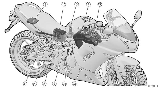
DFI: Digital Fuel Injection Parts 1. FI Indicator Light (LED) 2. Ignition Switch 3. Throttle Body Assy 4. Inlet Air Temperature Sensor 5. Injectors 6. Fuel Pump 7. Relay Box (ECU Main Relay, Fuel Pump Relay, Radiator Fan Relay) 8. Fuse Box (ECU Fuse 15 A, Oxygen Sen- sor Heater Fuse 10 A) 9. ECU 10. Battery 11. Oxygen Sensor (Europe Models) 12. Speed Sensor 13. Neutral Switch 14. Water Temperature Sensor 15. Subthrottle Sensor 16. Main Throttle Sensor 17. Subthrottle Valve Actuator 18. Stick Coils 19. Inlet Air Pressure Sensor 20. Diagnosis Connector 21. Self-diagnosis Terminal 22. Air Switching Valve 23. Crankshaft Sensor 24. Vehicle-down Sensor
|
||||||||||||||||||||||||||||||||||||||||||||||||||||||||||||||||||||||||||||||
|
|
Последнее изменение этой страницы: 2016-08-10; просмотров: 364; Нарушение авторского права страницы; Мы поможем в написании вашей работы! infopedia.su Все материалы представленные на сайте исключительно с целью ознакомления читателями и не преследуют коммерческих целей или нарушение авторских прав. Обратная связь - 18.223.239.65 (0.007 с.) |

 • Insert the spark plug vertically into the plug hole with the spark plug installed in the plug wrench [A].


 38 mm (1.50 in.)
Denso
Digital memory type, with built in IC igniter, sealed with resin
100 ~ 11 000 r/min (rpm) (Europe Models)
100 ~ 11 160 r/min (rpm) (Other than Europe Models)
323 kPa (3.3 kgf/cm², 47 psi) with fuel pump running 265 kPa (2.7 kgf/cm², 38 psi) with fuel pump stopped 333 kPa (3.4 kgf/cm², 48 psi) with fuel pump running
In-tank friction pump
60 mL or more for 3 seconds
INP-287
One spray type with 12 holes About 11.7 ~ 12.3 Ω at 20°C (68°F)
Non-adjustable and non-removable
4.75 ~ 5.25 V DC between BL and BR/BK leads
1.073 ~ 1.077 V DC between Y/W and BR/BK leads
4.29 ~ 4.49 V DC between Y/W and BR/BK leads 4 ~ 6 kΩ
4.75 ~ 5.25 V DC between BL and BR/BK leads
3.80 ~ 4.20 V DC at standard atmospheric pressure (see this text for details)
5.4 ~ 6.6 kΩ at 0°C (32°F)
0.29 ~ 0.39 kΩ at 80°C (176°F) About 2.25 ~ 2.50 V at 20°C (68°F)
see Electrical System chapter About 2.80 ~ 2.97 V at 20°C (68°F)
About 9 ~ 11 V DC at Ignition Switch ON
About 0.05 ~ 0.07 V DC at Ignition Switch ON and 0 km/h
Magnetic flux detection method more than 60 ~ 70° for each bank
38 mm (1.50 in.)
Denso
Digital memory type, with built in IC igniter, sealed with resin
100 ~ 11 000 r/min (rpm) (Europe Models)
100 ~ 11 160 r/min (rpm) (Other than Europe Models)
323 kPa (3.3 kgf/cm², 47 psi) with fuel pump running 265 kPa (2.7 kgf/cm², 38 psi) with fuel pump stopped 333 kPa (3.4 kgf/cm², 48 psi) with fuel pump running
In-tank friction pump
60 mL or more for 3 seconds
INP-287
One spray type with 12 holes About 11.7 ~ 12.3 Ω at 20°C (68°F)
Non-adjustable and non-removable
4.75 ~ 5.25 V DC between BL and BR/BK leads
1.073 ~ 1.077 V DC between Y/W and BR/BK leads
4.29 ~ 4.49 V DC between Y/W and BR/BK leads 4 ~ 6 kΩ
4.75 ~ 5.25 V DC between BL and BR/BK leads
3.80 ~ 4.20 V DC at standard atmospheric pressure (see this text for details)
5.4 ~ 6.6 kΩ at 0°C (32°F)
0.29 ~ 0.39 kΩ at 80°C (176°F) About 2.25 ~ 2.50 V at 20°C (68°F)
see Electrical System chapter About 2.80 ~ 2.97 V at 20°C (68°F)
About 9 ~ 11 V DC at Ignition Switch ON
About 0.05 ~ 0.07 V DC at Ignition Switch ON and 0 km/h
Magnetic flux detection method more than 60 ~ 70° for each bank

 Oil Pressure Gauge, 5 kgf/cm²: 57001-125