Заглавная страница Избранные статьи Случайная статья Познавательные статьи Новые добавления Обратная связь FAQ Написать работу КАТЕГОРИИ: ТОП 10 на сайте Приготовление дезинфицирующих растворов различной концентрацииТехника нижней прямой подачи мяча. Франко-прусская война (причины и последствия) Организация работы процедурного кабинета Смысловое и механическое запоминание, их место и роль в усвоении знаний Коммуникативные барьеры и пути их преодоления Обработка изделий медицинского назначения многократного применения Образцы текста публицистического стиля Четыре типа изменения баланса Задачи с ответами для Всероссийской олимпиады по праву 
Мы поможем в написании ваших работ! ЗНАЕТЕ ЛИ ВЫ?
Влияние общества на человека
Приготовление дезинфицирующих растворов различной концентрации Практические работы по географии для 6 класса Организация работы процедурного кабинета Изменения в неживой природе осенью Уборка процедурного кабинета Сольфеджио. Все правила по сольфеджио Балочные системы. Определение реакций опор и моментов защемления |
Bolts, Nuts and Fasteners Tightness InspectionСодержание книги
Поиск на нашем сайте
• Check the tightness of the bolts and nuts listed here. Also, check to see that each cotter pin is in place and in good condition. NOTE ○For the engine fasteners, check the tightness of them when the engine is cold (at room temperature).
Bolt, Nut and Fastener to be checked Engine: Clutch Lever Pivot Nut Engine Mounting Bolts and Nuts Exhaust Pipe Manifold Holder Nuts Muffler Body Mounting Bolts Wheels: Front Axle Front Axle Clamp Bolt Rear Axle Nut Rear Axle Nut Cotter Pin Brakes: Brake Lever Pivot Nut Brake Pedal Bolt Brake Rod Joint Cotter Pin Caliper Mounting Bolts Front Master Cylinder Clamp Bolts Rear Master Cylinder Mounting Bolts Suspension: Front Fork Clamp Bolts Rear Shock Absorber Bolt and Nut Swingarm Pivot Shaft Nut Steering: Steering Stem Head Bolt Handlebar Holder Bolts Others: Footpeg Stay Bolts Front Fender Bolts Sidestand Bolt
Replacement Parts Air Cleaner Element Replacement
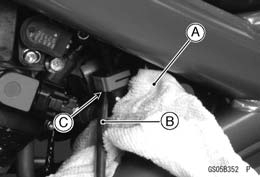
Fuel Hose Replacement • Remove: Fuel Tank (see Fuel Tank Removal in the Fuel System (DFI) chapter) Left Center Fairing (see Center Fairing Removal in the Frame chapter) • Be sure to place a piece of cloth [A] around the fuel hose joint. • Insert a minus screw driver [B] into the slit [C] on the joint lock.
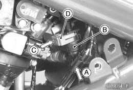
• Insert [A] the fuel hose joint [B] straight onto the delivery pipe until the hose joint clicks. • Push [C] the joint lock [D].
doesn’t come off.
• Run the fuel hose correctly (see Cable, Wire, and Hose Routing section in the Appendix chapter). • Install the removed parts (see appropriate chapters). • Start the engine and check the fuel hose for leaks.
Coolant Change
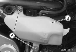
Right Center Fairing (see Center Fairing Removal in the Frame chapter) Reserve Tank Bolts [A] Reserve Tank [B]
the right side of frame.
it further in the same direction and remove the cap. ○The coolant will drain from the radiator and engine.
• Place the reserve tank on the right side of frame. • Tighten the drain bolt with the gasket. ○Replace the drain bolt gasket with a new one. Torque - Water Pump Drain Bolt: 7.0 N·m (0.70 kgf·m, 62 in·lb)
• When filling the coolant, choose a suitable mixture ratio by referring to the coolant manufacturer’s directions.
Water and Coolant Mixture Ratio (Recommended) Soft Water: 50% Coolant: 50% Freezing Point: –35°C (–31°F) Total Amount: 1.2 L (1.3 US qt)
NOTE ○Pour in the coolant slowly so that it can expel the air from the engine and radiator. • Check the cooling system for leaks. • Tap the radiator hoses to force any air bubbles caught inside. • Fill the radiator up to the filler neck with coolant.
• Fill the reserve tank up to the “F” (full) level line [A] with coolant and install the cap [B]. • Start the engine, warm it up thoroughly until the radiator fan turns on and then stop the engine. • Check the coolant level in the reserve tank after the en- gine cools down.
 If the coolant level is lower than the “L” level line, add coolant to the “F” level line. If the coolant level is lower than the “L” level line, add coolant to the “F” level line.
Radiator Hose and O-ring Replacement
• Remove: Thermostat Housing [A] (see Water Pump Removal in the Cooling System chapter) Water Pump Cover [B] (see Water Pump Removal in the Cooling System chapter) Hoses [C] O-rings [D] • Apply grease to the new O-rings and install them. • Install the new hoses and tighten the clamps securely. • Fill the coolant (see Coolant Change). • Check the cooling system for leaks.
• Situate the motorcycle so that it is vertical after warming up the engine. • Unscrew the oil filler plug [A]. • Place on oil pan beneath the engine.
○The oil in the oil filter can be drained by removing the filter (see Oil Filter Replacement).
• Tighten the drain bolt. Torque - Engine Oil Drain Bolt: 30 N·m (3.0 kgf·m, 22 ft·lb) • Pour in the specified type and amount of oil.
Type: API SE, SF or SG
|
||||||||||||||||
|
|
Последнее изменение этой страницы: 2016-08-10; просмотров: 286; Нарушение авторского права страницы; Мы поможем в написании вашей работы! infopedia.su Все материалы представленные на сайте исключительно с целью ознакомления читателями и не преследуют коммерческих целей или нарушение авторских прав. Обратная связь - 52.15.35.129 (0.011 с.) |

 • Refer to the Air Cleaner Element Cleaning.
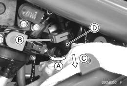 • Turn [A] the driver to disconnect the joint lock [B].
 • Install the new fuel hose.
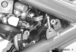 • Push and pull [A] the fuel hose joint [B] back and forth more than two times and make sure it is locked and

 • Remove:
 • Put [A] the projection [B] on the reserve tank into the hole [C] on the frame bracket, and place the reserve tank on
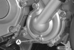 • Place a container under the water pump drain bolt [A], then remove the drain bolt.
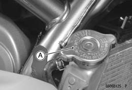 • Remove the radiator cap [A] in two steps. First turn the cap counterclockwise to the first stop. Then push and turn
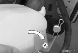 • Turn over [A] the reserve tank, remove the cap, and pour the coolant into a suitable container.
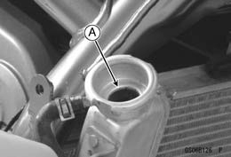 • Fill the radiator up to the filler neck [A] with coolant.
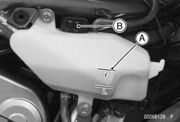 • Temporarily install the reserve tank to the frame with two bolts.
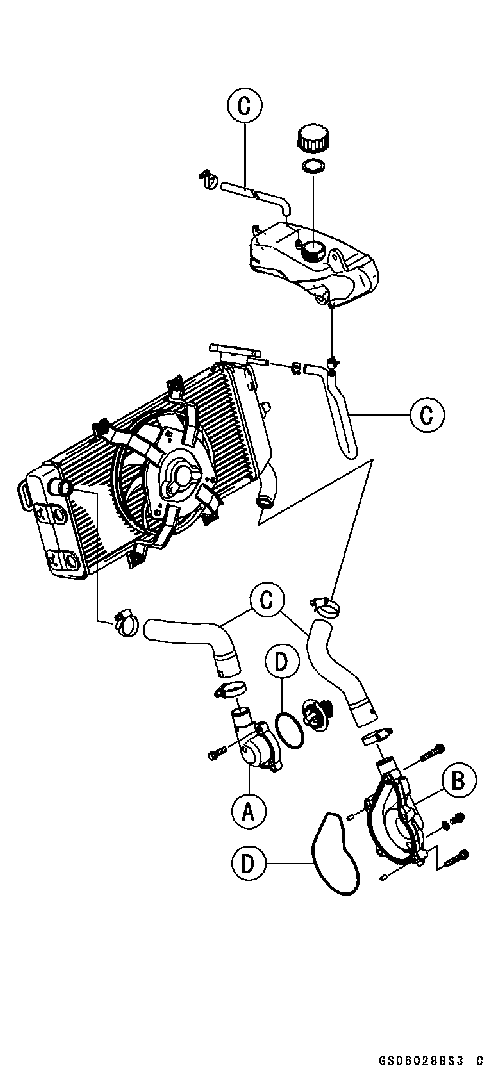 • Drain the coolant (see Coolant Change).
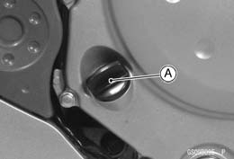 Engine Oil Change
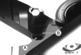 • Remove the engine oil drain bolt [A] to drain the oil.
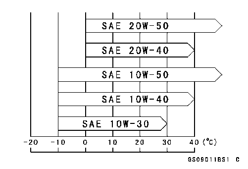 Recommended Engine Oil