Заглавная страница Избранные статьи Случайная статья Познавательные статьи Новые добавления Обратная связь FAQ Написать работу КАТЕГОРИИ: ТОП 10 на сайте Приготовление дезинфицирующих растворов различной концентрацииТехника нижней прямой подачи мяча. Франко-прусская война (причины и последствия) Организация работы процедурного кабинета Смысловое и механическое запоминание, их место и роль в усвоении знаний Коммуникативные барьеры и пути их преодоления Обработка изделий медицинского назначения многократного применения Образцы текста публицистического стиля Четыре типа изменения баланса Задачи с ответами для Всероссийской олимпиады по праву 
Мы поможем в написании ваших работ! ЗНАЕТЕ ЛИ ВЫ?
Влияние общества на человека
Приготовление дезинфицирующих растворов различной концентрации Практические работы по географии для 6 класса Организация работы процедурного кабинета Изменения в неживой природе осенью Уборка процедурного кабинета Сольфеджио. Все правила по сольфеджио Балочные системы. Определение реакций опор и моментов защемления |
Valve Clearance Measuring PositionСодержание книги
Поиск на нашем сайте
#2 Piston TDC at End of Compression Stroke → Inlet valve clearances of #2 piston, and Exhaust valve clearances of #2 piston
Valve Clearance Adjustment • To change the valve clearance, remove the camshaft chain tensioner, camshafts and valve lifters. Replace the shim with one of a different thickness.
○Mark and record the valve lifter and shim locations so they can be reinstalled in their original positions. ○If there is no clearance, select a shim which is several sizes smaller and then measure the clearance. • To select a new shim which brings the valve clearance within the specified range, refer to the Valve Clearance Adjustment Charts. • Apply a thin coat of molybdenum disulfide grease to the valve lifters. • Install the camshafts. Be sure to time the camshafts prop- erly (see Camshaft Installation in the Engine Top End chapter).
• Remeasure any valve clearance that was adjusted. Readjust if necessary.
1. Measure the clearance (when engine is cold). 2. Check present shim size. 3. Match clearance in vertical column with present shim size in horizontal column. 4. Install the shim specified where the lines intersect. This shim will give the proper clearance. Example: Present shim is 2.95 mm. Measured clearance is 0.45 mm. Replace 2.95 mm shim with 3.20 mm shim. 5. Remeasure the valve clearance and readjust if necessary.
1. Measure the clearance (when engine is cold). 2. Check present shim size. 3. Match clearance in vertical column with present shim size in horizontal column. 4. Install the shim specified where the lines intersect. This shim will give the proper clearance. Example: Present shim is 2.95 mm. Measured clearance is 0.47 mm. Replace 2.95 mm shim with 3.15 mm shim. 5. Remeasure the valve clearance and readjust if necessary.
Clutch Operation Inspection • Pull the clutch lever just enough to take up the free play [A]. • Measure the gap between the lever and the lever holder.
the gap is too narrow, the clutch may not engage fully. In either case, adjust it. Clutch Lever Free Play Standard: 2 ~ 3 mm (0.08 ~ 0.12 in.)
• Turn the adjuster [A] so that 5 ~ 6 mm (0.20 ~ 0.24 in.) [B] of threads are visible.
• Slide the dust cover [A] at the middle of the clutch cable out of place. • Loosen the locknut [B] at the middle of clutch cable.
• After the adjustment, tighten the locknut and start the en- gine and check that the clutch does not slip and that it releases properly.
Air Pressure Inspection • Remove the air valve cap. • Measure the tire air pressure with an air pressure gauge [A] when the tires are cold (that is, when the motorcycle has not been ridden more than a mile during the past 3 hours). • Install the air valve cap.
if necessary. Air Pressure (when Cold) Front: Up to 180 kg (397 lb) 225 kPa (2.25 kgf/cm², 32 psi) Rear: Up to 180 kg (397 lb) 250 kPa (2.50 kgf/cm², 36 psi)
• Remove any imbedded stones [A] or other foreign parti- cles [B] from tread. • Visually inspect the tire for cracks and cuts, and replace the tire if necessary. Swelling or high spots indicate inter- nal damage, requiring tire replacement. • Visually inspect the wheel for cracks, cuts and dents dam- age.
As the tire tread wears down, the tire becomes more sus- ceptible to puncture and failure. An accepted estimate is that 90% of all tire failures occur during the last 10% of tread life (90% worn). So it is false economy and unsafe to use the tires until they are bald. • Measure the tread depth at the center of the tread with a depth gauge [A]. Since the tire may wear unevenly, take measurement at several places.
Tread Depth Standard: Front 4.3 mm (0.17 in.) Rear 7.0 mm (0.28 in.) Service Limit: Front 1 mm (0.04 in.) (AT, CH, DE) 1.6 mm (0.06 in.) Rear 2 mm (0.08 in.) (Up to 130 km/h (80 mph)) Mm (0.12 in.)
(Over 130 km/h (80 mph)) NOTE ○Most countries may have their own regulations a mini- mum tire tread depth: be sure to follow them. ○Check and balance the wheel when a tire is replaced with a new one.
• Raise the front wheel off the ground with jack (see Front Wheel Removal in the Wheels/Tires chapter). • Turn the handlebar all the way to the right or left. • Inspect the roughness of the front wheel bearing by push- ing and pulling [A] the wheel. • Spin [B] the front wheel lightly, and check for smoothly turn, roughness, binding or noise.
• Inspect the roughness of the rear wheel bearing by push- ing and pulling [A] the wheel. • Spin [B] the rear wheel lightly, and check for smoothly turn, roughness, binding or noise.
Drive Train Drive Chain Lubrication Condition Inspection • If a special lubricant is not available, a heavy oil such as SAE 90 is preferred to a lighter oil because it will stay on the chain longer and provide better lubrication.
• If the chain appears especially dirty, clean it before lubri- cation.
that the O-rings will be coated with oil. • Wipe off any excess oil. Oil Applied Areas [A] O-rings [B]
NOTE ○Check the slack with the motorcycle setting on its side- stand. ○Clean the chain if it is dirty, and lubricate it if it appears dry. • Check the wheel alignment (see Wheel Alignment Inspec- tion). • Rotate the rear wheel to find the position where the chain is tightest. • Measure the vertical movement (chain slack) [A] midway between the sprockets.
Chain Slack Standard: 30 ~ 40 mm (1.2 ~ 1.6 in.)
• Remove the cotter pin [A], and loosen the axle nut [B]. • Loosen the both chain adjuster locknuts [C].
adjuster nuts [D] evenly.
• Turn both chain adjuster nuts evenly until the drive chain has the correct amount of slack. To keep the chain and
wheel properly aligned, the value [E] on the left wheel alignment adjuster [F] should align with the same (left or right) edge [G] of inspection window on the swingarm that the right wheel alignment adjuster value aligns with. • Tighten both chain adjuster locknuts securely. • Tighten the axle nut. Torque - Rear Axle Nut: 108 N·m (11.0 kgf·m, 80 ft·lb) • Turn the wheel, measure the chain slack again at the tight- est position, and readjust if necessary.
NOTE ○When inserting the cotter pin, if the slots in the nut do not align with the cotter pin hole in the axle, tighten the nut clockwise [B] up to next alignment. ○It should be within 30°. ○Loosen once and tighten again when the slot goes past the nearest hole.
 • Bend the cotter pin [A] over the nut [B]. • Bend the cotter pin [A] over the nut [B].
• Check that the value [A] on the left wheel alignment ad- juster [B] aligns with the same (left or right) edge [C] of inspection window on the swingarm that the right wheel alignment adjuster value aligns with.
NOTE ○Wheel alignment can be also checked using the straightedge or string method.
• Remove: Chain Cover (see Swingarm Removal in the Suspension chapter) • Rotate the rear wheel to inspect the drive chain for dam- aged rollers, and loose pins and links.
• Stretch the chain taut by hanging a 98 N (10 kg, 20 lb) weight [A] on the chain. • Measure the length of 20 links [B] on the straight part [C] of the chain from the pin center of the 1st pin to the pin center of the 21st pin. Since the chain may wear unevenly, take measurements at several places.
Drive Chain 20-link Length Standard: 317.5 ~ 318.2 mm (12.50 ~ 12.53 in.)
Service Limit: 323 mm (12.7 in.) Standard Chain Make: ENUMA Type: EK520MVXL1 Link: 114 links
• Remove: Swingarm (see Swingarm Removal in the Suspension chapter) • Visually inspect the chain guide [A].
wear or damage.
Brake Fluid Leak (Brake Hose and Pipe) Inspection • Apply the brake lever or pedal and inspect the brake fluid leak from the brake hoses [A], fittings [B] and pipes [C].
• Inspect the brake hoses, fittings and pipes for deteriora- tion, cracks and signs of leakage. ○The high pressure inside the brake line can cause fluid to leak [A] or the hose to burst if the line is not properly main- tained. Bend and twist the rubber hose while examining it.
Torque - Brake Hose Banjo Bolts: 25 N·m (2.5 kgf·m, 18 ft·lb) Brake Pipe Joint Nuts: 18 N·m (1.8 kgf·m, 13 ft·lb) (EX650B Models) • Inspect the brake hose routing.
according to Cable, Wire, and Hose Routing section in the Appendix chapter.
Brake Operation Inspection • Inspect the operation of the front and rear brake by run- ning the vehicle on the dry road.
 If the brake operation is insufficiency, inspect the brake system. If the brake operation is insufficiency, inspect the brake system.
• Check that the brake fluid level in the front brake reservoir [A] is above the lower level line [B]. NOTE ○Hold the reservoir horizontal by turning the handlebar when checking brake fluid level.
• Remove the seat (see Seat Removal in the Frame chap- ter).
[A] is above the lower level line [B].
If the fluid level is lower than the lower level line, fill the reservoir to the upper level line [C].
|
||||||||||||||||||||||||||||||||||||||||||||
|
|
Последнее изменение этой страницы: 2016-08-10; просмотров: 554; Нарушение авторского права страницы; Мы поможем в написании вашей работы! infopedia.su Все материалы представленные на сайте исключительно с целью ознакомления читателями и не преследуют коммерческих целей или нарушение авторских прав. Обратная связь - 18.218.121.8 (0.011 с.) |

 NOTE
NOTE

 Clutch

 • Remove the right center fairing (see Center Fairing Re- moval in the Frame chapter).
 Wheels/Tires
 Wheel/Tire Damage Inspection
 Tire Tread Wear, Abnormal Wear Inspection
 If any measurement is less than the service limit, replace the tire (see Tire Removal/Installation in the Wheels/Tires chapter).
 Wheel Bearing Damage Inspection
 • Raise the rear wheel off the ground with stand (see Rear Wheel Removal in the Wheels/Tires chapter).
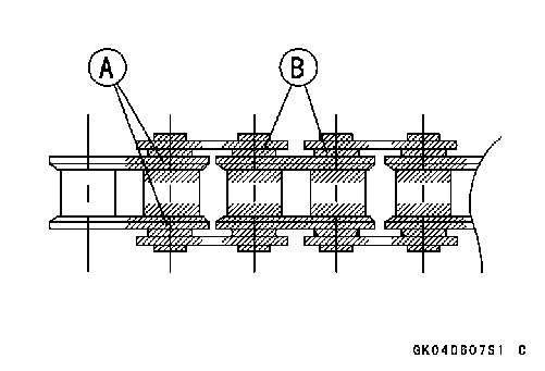 • Apply oil to the sides of the rollers so that oil will penetrate to the rollers and bushings. Apply the oil to the O-rings so
 Drive Chain Slack Inspection
 Drive Chain Slack Adjustment
 • Insert a new cotter pin [A].
 Wheel Alignment Inspection
 Drive Chain Wear Inspection
 Chain Guide Inspection
 Brake System

 Brake Hose and Pipe Damage and Installation Condition Inspection
 Brake Fluid Level Inspection
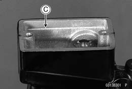
 • Check that the brake fluid level in the rear brake reservoir