Заглавная страница Избранные статьи Случайная статья Познавательные статьи Новые добавления Обратная связь FAQ Написать работу КАТЕГОРИИ: ТОП 10 на сайте Приготовление дезинфицирующих растворов различной концентрацииТехника нижней прямой подачи мяча. Франко-прусская война (причины и последствия) Организация работы процедурного кабинета Смысловое и механическое запоминание, их место и роль в усвоении знаний Коммуникативные барьеры и пути их преодоления Обработка изделий медицинского назначения многократного применения Образцы текста публицистического стиля Четыре типа изменения баланса Задачи с ответами для Всероссийской олимпиады по праву 
Мы поможем в написании ваших работ! ЗНАЕТЕ ЛИ ВЫ?
Влияние общества на человека
Приготовление дезинфицирующих растворов различной концентрации Практические работы по географии для 6 класса Организация работы процедурного кабинета Изменения в неживой природе осенью Уборка процедурного кабинета Сольфеджио. Все правила по сольфеджио Балочные системы. Определение реакций опор и моментов защемления |
Sealant - Kawasaki Bond (Silicone Sealant): 92104-0004Содержание книги
Поиск на нашем сайте
• Install: Dowel Pins [C] Plug Hole Gaskets [D]
Washers [A] Cylinder Head Cover Bolts [B] ○Install the washers with metal side [C] faces upward. • Tighten: Torque - Cylinder Head Cover Bolts: 9.8 N·m (1.0 kgf·m, 87 in·lb)
• Install the baffle plate [A]. • Tighten: Torque - Baffle Plate Bolts [B]: 5.9 N·m (0.60 kgf·m, 52 in·lb)
Camshaft Chain Tensioner Removal
Right Center Fairing (see Center Fairing Removal in the Frame chapter) Cap Bolt [A] Washer [B] Spring [C] • Remove the mounting bolts [D] and take off the camshaft chain tensioner.
• Release the stopper [A] and push the push rod [B] into the tensioner [C]. • Install the tensioner so that the stopper faces upward.
Torque - Camshaft Chain Tensioner Mounting Bolts: 9.8 N·m (1.0 kgf·m, 87 in·lb) • Install the spring and washer. • Tighten the cap bolt [B]. Torque - Camshaft Chain Tensioner Cap Bolt: 20 N·m (2.0 kgf·m, 15 ft·lb) • Turn the crankshaft 2 turns clockwise to allow the ten- sioner to expand and recheck the camshaft chain timing.
Camshaft Removal
Cylinder Head Cover (see Cylinder Head Cover Re- moval) Right Lower Fairing (see Lower Fairing Removal in the Frame chapter) • Position the crankshaft as follows. ○Remove the upper [A] and lower [B] caps on the clutch cover.
Camshaft Chain Tensioner (see Camshaft Chain Ten-
sioner Removal) Camshaft Cap Bolts [A] Camshaft Caps [B] Camshafts [C] Camshaft Installation
Dowel Pins [B]
• Apply molybdenum disulfide oil solution to all cams [A] journals [B] and thrust blocks [C] with × marks. • If a new camshaft is to be used, apply a thin coat of molyb- denum disulfide grease to the cam surfaces. NOTE ○The exhaust camshaft has a 2 412 EX mark [D] and the inlet camshaft has a 2 412 IN mark [E]. Be careful not to mix up these shafts.
• Pull the tension side (exhaust side) of the chain taut to install the chain. • Engage the camshaft chain with the camshaft sprockets so that the timing marks on the sprockets are positioned as shown. ○Using a wrench on the crankshaft rotation bolt, turn the crankshaft clockwise until the 2/T mark line [A] on the tim- ing rotor is aligned with the notch [B] in the edge of the upper hole [C] in the clutch cover.
○Using a wrench on the crankshaft rotation bolt, turn the crankshaft clockwise until the 1/T mark line [A] on the timing rotor is aligned with the wating surface [B] of the crankcase halves.
○The timing marks must be aligned with the cylinder head upper surface [C]. EX Mark [D] (Between #1 Pin and #2 Pin) IN Mark [E] (Between #31 Pin and #32 Pin) #1 Pin [F] #2 Pin [G] #31 Pin [H]
NOTE ○The exhaust cap has a “EX” mark [A] and the inlet cap has a “IN” mark [B]. Be careful not to mix up these caps. ○First tighten all the camshaft cap bolts evenly to seat the camshaft in place, then tighten all bolts following the spec- ified tightening sequence. Torque - Camshaft Cap Bolts (1 ~ 12): 12 N·m (1.2 kgf·m, 106 in·lb) • Install: Camshaft Chain Tensioner (see Camshaft Chain Ten- sioner Installation) Cylinder Head Cover (see Cylinder Head Cover Instal- lation) Right Lower Fairing (see Lower Fairing Removal in the Frame chapter)
○The inlet and exhaust sprockets are identical.
• Install the sprockets so that the marked (“IN” and “EX”) side faces to the right side. • Apply a non-permanent locking agent to the camshaft sprockets bolts and tighten them. Torque - Camshaft Sprockets Bolts: 15 N·m (1.5 kgf·m, 11 ft·lb)
• Remove: Camshaft Caps (see Camshaft Removal) • Cut strips of plastigage to journal width. Place a strip on each journal parallel to the camshaft installed in the correct position. • Measure each clearance between the camshaft journal and the camshaft cap using plastigage (press gauge) [A]. • Tighten: Torque - Camshaft Cap Bolts: 12 N·m (1.2 kgf·m, 106 in·lb) NOTE ○Do not turn the camshaft when the plastigage is be- tween the journal and camshaft cap.
|
||||||||||
|
|
Последнее изменение этой страницы: 2016-08-10; просмотров: 537; Нарушение авторского права страницы; Мы поможем в написании вашей работы! infopedia.su Все материалы представленные на сайте исключительно с целью ознакомления читателями и не преследуют коммерческих целей или нарушение авторских прав. Обратная связь - 18.225.156.91 (0.008 с.) |

 • Install:
 Cylinder Head Cover
 • Remove:
 Camshaft Chain Tensioner Installation
 • Tighten the tensioner mounting bolts [A].
 • Remove:
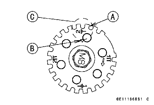 ○Using a wrench on the crankshaft rotation bolt, turn the crankshaft clockwise until the 2/T mark line [A] on the tim- ing rotor is aligned with the notch [B] in the edge of the upper hole [C] in the clutch cover.
 • Remove:
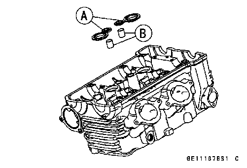 • Be sure to install the following parts. Plug Hole Gaskets [A]
 • Position the crankshaft as follows.
 • If the clutch cover is removed, perform the next proce- dure.
 • Install the camshaft cap, while pushing the camshaft chain, tighten all camshaft bolts and chain guide bolts.
 Camshaft and Sprocket Assembly
 If a new camshaft is to be used, apply a thin coat of a molybdenum disulfide grease to the cam surfaces.
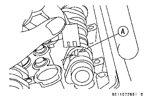 Camshaft, Camshaft Cap Wear