Заглавная страница Избранные статьи Случайная статья Познавательные статьи Новые добавления Обратная связь FAQ Написать работу КАТЕГОРИИ: ТОП 10 на сайте Приготовление дезинфицирующих растворов различной концентрацииТехника нижней прямой подачи мяча. Франко-прусская война (причины и последствия) Организация работы процедурного кабинета Смысловое и механическое запоминание, их место и роль в усвоении знаний Коммуникативные барьеры и пути их преодоления Обработка изделий медицинского назначения многократного применения Образцы текста публицистического стиля Четыре типа изменения баланса Задачи с ответами для Всероссийской олимпиады по праву 
Мы поможем в написании ваших работ! ЗНАЕТЕ ЛИ ВЫ?
Влияние общества на человека
Приготовление дезинфицирующих растворов различной концентрации Практические работы по географии для 6 класса Организация работы процедурного кабинета Изменения в неживой природе осенью Уборка процедурного кабинета Сольфеджио. Все правила по сольфеджио Балочные системы. Определение реакций опор и моментов защемления |
Radiator Cap Relief PressureСодержание книги
Поиск на нашем сайте
Standard: 112.3 ~ 141.7 kPa (1.15 ~ 1.45 kgf/cm², 16.3 ~ 20.5 psi)
• Remove the reserve tank (see Coolant Change in the Pe- riodic Maintenance chapter). • Remove the radiator cap. • Check the radiator filler neck for signs of damage. • Check the condition of the top and bottom sealing seats [A] in the filler neck. They must be smooth and clean for the radiator cap to function properly.
Thermostat Removal
• Remove: Left Center Fairing (see Center Fairing Removal in the Frame chapter) Thermostat Hosing Bolts [A] Thermostat Hosing [B]
• Install the thermostat [A] in the cylinder head so that the air bleeder hole [B] is on top. • Install a new O-ring into the housing and apply grease it. • Tighten: Torque - Thermostat Hosing Bolts: 9.8 N·m (1.0 kgf·m, 87 in·lb) • Fill the radiator with coolant (see Coolant Change in the Periodic Maintenance chapter).
• Remove the thermostat, and inspect the thermostat valve [A] at room temperature.
• To check valve opening temperature, suspend the ther- mostat [A] in a container of water and raise the tempera- ture of the water. ○The thermostat must be completely submerged and must not touch the container sides or bottom. Suspend an ac- curate thermometer [B] in the water so that the heat sen- sitive portions [C] are located in almost the same depth. It must not touch the container, either.
Thermostat Valve Opening Temperature 80.5 ~ 83.5°C (177 ~ 182°F)
Hose Installation
twisting. • Run the hoses (see Cable, Wire, and Hose Routing sec- tion in the Appendix chapter). • Install the clamp [A] as near as possible to the hose end to clear the raised rib of the fitting. This will prevent the hoses from working loose. ○The clamp screws should be positioned correctly to pre- vent the clamps from contacting the other parts. Torque - Radiator Hose Clamp Screws: 2.0 N·m (0.20 kgf·m, 17 in·lb) Hose Inspection • Refer to the Radiator Hose Damage and Installation Con- dition Inspection in the Periodic Maintenance chapter.
• Refer to the Water Temperature Sensor Removal/Instal- lation in the Fuel System (DFI) chapter. Water Temperature Sensor [A]
Water Temperature Sensor Inspection • Refer to the Water Temperature Sensor Inspection in the Electrical System chapter.
Engine Top End Table of Contents Exploded View........................................................................................................................ 5-3 Exhaust System...................................................................................................................... 5-8 Specifications......................................................................................................................... 5-10 Special Tools and Sealant...................................................................................................... 5-12 Clean Air System.................................................................................................................... 5-14 Air Suction Valve Removal................................................................................................ 5-14 Air Suction Valve Installation............................................................................................. 5-14 Air Suction Valve Inspection............................................................................................. 5-14 5 Air Switching Valve Removal............................................................................................ 5-14 Air Switching Valve Installation......................................................................................... 5-14 Air Switching Valve Operation Test................................................................................... 5-15 Air Switching Valve Unit Test............................................................................................ 5-15 Clean Air System Hose Inspection................................................................................... 5-15 Cylinder Head Cover.............................................................................................................. 5-16 Cylinder Head Cover Removal......................................................................................... 5-16 Cylinder Head Cover Installation...................................................................................... 5-16 Camshaft Chain Tensioner..................................................................................................... 5-18 Camshaft Chain Tensioner Removal................................................................................ 5-18 Camshaft Chain Tensioner Installation............................................................................. 5-18 Camshaft, Camshaft Chain.................................................................................................... 5-19 Camshaft Removal........................................................................................................... 5-19 Camshaft Installation........................................................................................................ 5-19 Camshaft and Sprocket Assembly.................................................................................... 5-22 Camshaft, Camshaft Cap Wear........................................................................................ 5-22 Camshaft Runout.............................................................................................................. 5-23 Cam Wear......................................................................................................................... 5-23 Camshaft Chain Removal................................................................................................. 5-23 Cylinder Head......................................................................................................................... 5-24 Cylinder Compression Measurement................................................................................ 5-24 Cylinder Head Removal.................................................................................................... 5-25 Cylinder Head Installation................................................................................................. 5-26 Cylinder Head Warp.......................................................................................................... 5-28 Valves..................................................................................................................................... 5-29 Valve Clearance Inspection.............................................................................................. 5-29 Valve Clearance Adjustment............................................................................................. 5-29 Valve Removal.................................................................................................................. 5-29 Valve Installation............................................................................................................... 5-29 Valve Guide Removal....................................................................................................... 5-29 Valve Guide Installation.................................................................................................... 5-30 Valve-to-Guide Clearance Measurement (Wobble Method)............................................. 5-30 Valve Seat Inspection....................................................................................................... 5-31 Valve Seat Repair............................................................................................................. 5-31 Cylinder, Pistons..................................................................................................................... 5-36 Cylinder Removal.............................................................................................................. 5-36 Cylinder Installation........................................................................................................... 5-36 Piston Removal................................................................................................................. 5-36 Piston Installation.............................................................................................................. 5-37 Cylinder Wear................................................................................................................... 5-38 Piston Wear...................................................................................................................... 5-38 Piston Ring, Piston Ring Groove Wear............................................................................. 5-39
Piston Ring Groove Width................................................................................................. 5-39 Piston Ring Thickness...................................................................................................... 5-39 Piston Ring End Gap........................................................................................................ 5-40 Throttle Body Holder............................................................................................................... 5-41 Throttle Body Holder Installation....................................................................................... 5-41 Muffler..................................................................................................................................... 5-42 Muffler Body Removal....................................................................................................... 5-42 Exhaust Pipe Removal...................................................................................................... 5-42 Muffler Body and Exhaust Pipe Installation...................................................................... 5-43
Dummy Page
L: Apply a non-permanent locking agent. M: Apply molybdenum disulfide grease. MO: Apply molybdenum disulfide oil solution. (mixture of the engine oil and molybdenum disulfide grease in a weight ratio 10: 1) R: Replacement Parts S: Follow the specified tightening sequence. SS: Apply silicone sealant.
7. "R" marked side faces up. 8. "RN" marked side faces up. 9. Hollow mark faces forward. MO: Apply molybdenum disulfide oil solution. (mixture of the engine oil and molybdenum disulfide grease in a weight ratio 10: 1) R: Replacement Parts S: Follow the specified tightening sequence.
Exhaust System EX650A6F/EX650B6F
Full: Full Power H: Honeycomb Type Catalyst
Manifold Mark Position [A]
Valve Seat Cutter, 60° -
|
||||||||||||||||||||||||||||||||||||||||||||||||||||||||||||||||||||||||||||||||||||||||||||||||||||||||||||||||||||||||||||||||||||||||||||||||||||||||||||||||||||||||||||||||||||||||||||||||||||||||||||||||||||||||||||||||||||||||||||
|
|
Последнее изменение этой страницы: 2016-08-10; просмотров: 296; Нарушение авторского права страницы; Мы поможем в написании вашей работы! infopedia.su Все материалы представленные на сайте исключительно с целью ознакомления читателями и не преследуют коммерческих целей или нарушение авторских прав. Обратная связь - 18.119.248.48 (0.01 с.) |

 If the cap can not hold the specified pressure or if it holds too much pressure, replace it with a new one.
 Radiator Filler Neck Inspection
 • Drain the coolant (see Coolant Change in the Periodic Maintenance chapter).
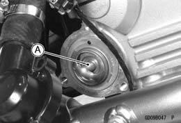 • Pull the thermostat [A] out of the cylinder head.
 Thermostat Installation
 Thermostat Inspection
 If the valve is open, replace the thermostat with a new one.
 Thermostat
 • Install the hoses and pipes, being careful to follow bend- ing direction. Avoid sharp bending, kinking, flattening or
 Water Temperature Sensor Removal/Installation


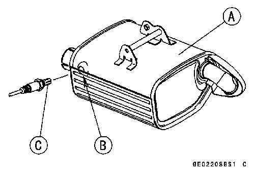 Silencer [A] with Hole [B] for Oxygen Sensor [C]
 Silencer Mark Position [A]
 Compression Gauge, 20 kgf/cm²: 57001-221
 30:
30: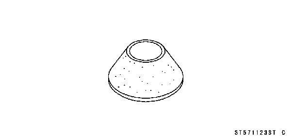 57001-1123
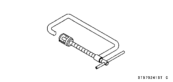
 Valve Spring Compressor Assembly: 57001-241