Заглавная страница Избранные статьи Случайная статья Познавательные статьи Новые добавления Обратная связь FAQ Написать работу КАТЕГОРИИ: ТОП 10 на сайте Приготовление дезинфицирующих растворов различной концентрацииТехника нижней прямой подачи мяча. Франко-прусская война (причины и последствия) Организация работы процедурного кабинета Смысловое и механическое запоминание, их место и роль в усвоении знаний Коммуникативные барьеры и пути их преодоления Обработка изделий медицинского назначения многократного применения Образцы текста публицистического стиля Четыре типа изменения баланса Задачи с ответами для Всероссийской олимпиады по праву 
Мы поможем в написании ваших работ! ЗНАЕТЕ ЛИ ВЫ?
Влияние общества на человека
Приготовление дезинфицирующих растворов различной концентрации Практические работы по географии для 6 класса Организация работы процедурного кабинета Изменения в неживой природе осенью Уборка процедурного кабинета Сольфеджио. Все правила по сольфеджио Балочные системы. Определение реакций опор и моментов защемления |
Fork Oil Level Gauge: 57001-1290Содержание книги
Поиск на нашем сайте
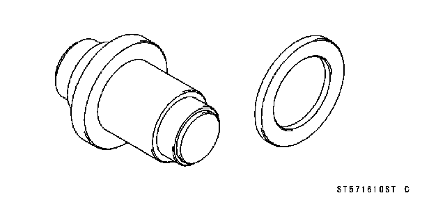
Oil Seal & Bearing Remover: 57001-1058 Jack Attachment: 57001-1608
Bearing Driver Set: 57001-1129 Stem Bearing Driver,
Spacer, 57001-1663
Front Fork Removal
Upper Inner Fairing (see Upper Inner Fairing Removal in the Frame chapter) Front Wheel (see Front Wheel Removal in the Wheels/Tires chapter) Front Fender (see Front Fender Removal in the Frame chapter) Front Wheel Rotation Sensor (see Front Wheel Rotation Sensor Removal in the Brakes chapter) (EX650B Mod- els)
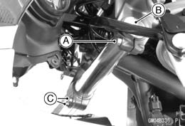
NOTE ○Loosen the top plug after loosening the upper fork clamp bolt. • Loosen the upper fork clamp bolt and lower fork clamp bolts [C].
Front Fork Installation • Install the fork so that the top end [A] of the inner tube as shown. 10 mm (0.40 in.) [B] • Tighten: Torque - Front Fork Clamp Bolts (Lower): 20 N·m (2.0 kgf·m, 15 ft·lb) Front Fork Top Plug: 25 N·m (2.5 kgf·m, 18 ft·lb) NOTE ○Tighten the top plug before tightening the upper fork clamp bolt. ○Tighten the two clamp bolts alternately two times to en- sure even tightening torque. • Tighten: Torque - Front Fork Clamp Bolt (Upper): 20 N·m (2.0 kgf·m, 15 ft·lb)
Front Fork Oil Change • Remove the front fork (see Front Fork Removal). • Remove: Top Plug [A] with O-ring Collar [B] Fork Spring Seat [C] Fork Spring [D]
• Compress [A] the fork [B] upside down to draw out the oil into the suitable container [C].
Fork Oil Viscosity: KAYABA KHL34-G10 or equivalent Amount (Per Side): When changing oil: EX650A Models approx. 415 mL (14.0 US oz.) EX650B Models approx. 420 mL (14.2 US oz.) After disassembly and completely dry: EX650A Models 489 ±4 mL (16.5 ±0.14 US oz.) EX650B Models 498 ±3 mL (16.8 ±0.10 US oz.) NOTE ○Move the outer tube up and down a few times to remove the air that is trapped in the fork oil in order to stabilize the oil level.
• Wait until the oil level stabilizes. • Use the fork oil level gauge [A] to measure the distance between the top of the inner tube to the oil level. Special Tool - Fork Oil Level Gauge: 57001-1290 ○Setthe oil level gauge stopper [B] so that the distance [C] from the bottom of the stopper to the lower end of the pipe is the standard oil level distance. ○A correct measurement can not be obtained unless the level gauge pipe is placed in the center of the inner tube. Oil Level (fully compressed, without spring) Standard: EX650A Models 98 ±2 mm (3.9 ±0.08 in.) EX650B Models 89 ±2 mm (3.5 ±0.08 in.) ○Place the stopper of the level gauge at the top [D] of the inner tube [E] and pull the handle slowly to draw out the excess oil from fork into the gauge, thus attaining the stan- dard level. ○If not oil is drawn out, there is not enough oil in the fork. Pour in some more oil and measure again.
• Install the fork spring [A], fork spring seat [B] and collar [C]. • Inspect the top plug O-ring and replace it with a new one. • Install the front fork (see Front Fork Installation).
• Remove the front fork (see Front Fork Removal). • Remove the top plug [A] with O-ring, take out the collar [B], fork spring seat [C], and fork spring [D]. • Drain the fork oil (see Front Fork Oil Change).
Special Tools - Fork Cylinder Holder Handle [B]: 57001-183 Fork Cylinder Holder Adapter [C]: 57001 -1057 NOTE ○Hold the outer tube in a vise [D], stop the cylinder unit [E] from turning by using the special tools, and unscrew the Allen bolt.
Retaining Ring [B]
NOTE ○From the compressed state, firmly pull down the outer tube a few times towards the direction of elongation.
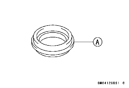
Outer Guide Bushing [B] Washer [C] Oil Seal [D]
• Check the top plug O-ring and replace it with a new one. • Replace the following parts with new ones. Retaining Ring [A] Dust Seal [B] Oil Seal [C] Inner Guide Bushing [D] Outer Guide Bushing [E] Fork Bottom Allen Bolt Gasket [F]
• Insert the cylinder unit and the spring into the inner tube, and install the cylinder base [A] onto the cylinder end [B] that protrudes from the bottom. ○Install the cylinder base starting with its stepped end. • Insert the inner tube, cylinder unit, washer, spring, and cylinder base as a set into the outer tube.
• After installing the washer, install the oil seal [A] by using the fork oil seal driver [B]. Special Tool - Fork Oil Seal Driver, • Install the retaining ring into the outer tube. • Install the dust seal by hand.
• Hold the front fork horizontally in a vise [B]. • Hold the cylinder unit [C] with the special tools and tighten the bottom Allen bolt to secure the cylinder in place. Torque - Front Fork Bottom Allen Bolt: 30 N·m (3.1 kgf·m, 22 ft·lb) Special Tools - Fork Cylinder Holder Handle [D]: 57001-183 Fork Cylinder Holder Adapter [E]: 57001 -1057 • Pour in the specified type of oil (see Front Fork Oil Change).
• Visually inspect the inner tube [A], and repair any dam- age. • Nicks or rust damage can sometimes be repaired by using a wet-stone to remove sharp edges or raised areas which cause seal damage.
 If the damage is not repairable, replace the inner tube. Since damage to the inner tube damages the oil seal, replace the oil seal whenever the inner tube is repaired or replaced. If the damage is not repairable, replace the inner tube. Since damage to the inner tube damages the oil seal, replace the oil seal whenever the inner tube is repaired or replaced.
• Temporarily assemble the inner and outer tubes, and pump them back and forth manually to check for smooth operation.
• If you feel binding or catching, the inner and outer tubes must be replaced. Dust Seal Inspection
• Measure the free length [A] of the fork spring [B].
spring must be replaced. If the free length of the replace- ment spring and that of the remaining spring vary greatly, the remaining spring should also be replaced in order to keep the fork legs balanced to ensure stability. Fork Spring Free Length Standard: 277.2 mm (10.91 in.)
|
||||||||
|
|
Последнее изменение этой страницы: 2016-08-10; просмотров: 741; Нарушение авторского права страницы; Мы поможем в написании вашей работы! infopedia.su Все материалы представленные на сайте исключительно с целью ознакомления читателями и не преследуют коммерческих целей или нарушение авторских прав. Обратная связь - 13.59.67.189 (0.005 с.) |


 28: 57001-1610
 28:
28: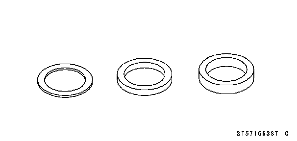
 • Remove:
 • With a twisting motion, work the fork leg down and out.
 • Install the removed parts (see appropriate chapters).
 • Pour in the specified amount of oil.
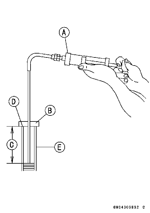 • Hold the outer tube vertically in a vise and compress the fork completely.
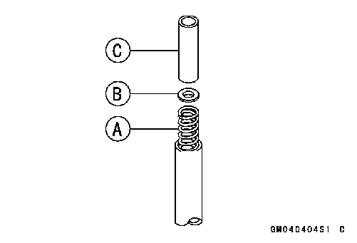 • Repeat the same procedure for adjusting the other fork.
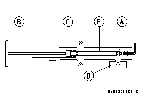 • Remove the Allen bolt [A] from the bottom of the fork.
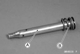 • Remove the cylinder unit [A], washer, and the spring [B] from the inner tube.
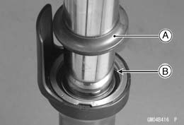 • Remove the following from the top of the outer tube. Dust Seal [A]
 • Separate the inner tube [A] from the outer tube [B].
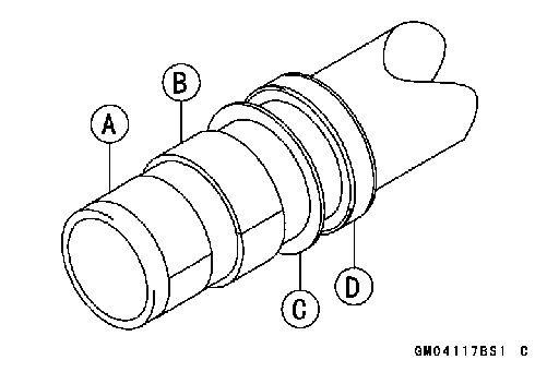 • Remove the following from the inner tube. Inner Guide Bushing [A]
 • Remove the cylinder base [A] from the bottom of the outer tube.
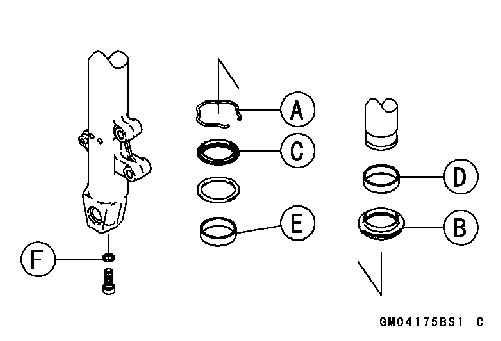 Front Fork Assembly
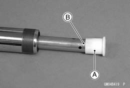 • Install the guide bushing on the end of the inner tube.
 • Install the guide bushing into the outer tube.
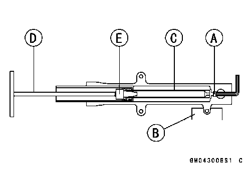 • Apply non-permanent locking agent to the threads of the bottom Allen bolt [A].
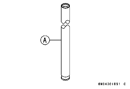 Inner Tube Inspection
 • Inspect the dust seal [A] for any signs of deterioration or damage.
 Fork Spring Inspection