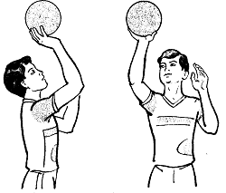
Заглавная страница Избранные статьи Случайная статья Познавательные статьи Новые добавления Обратная связь FAQ Написать работу КАТЕГОРИИ: ТОП 10 на сайте Приготовление дезинфицирующих растворов различной концентрацииТехника нижней прямой подачи мяча. Франко-прусская война (причины и последствия) Организация работы процедурного кабинета Смысловое и механическое запоминание, их место и роль в усвоении знаний Коммуникативные барьеры и пути их преодоления Обработка изделий медицинского назначения многократного применения Образцы текста публицистического стиля Четыре типа изменения баланса Задачи с ответами для Всероссийской олимпиады по праву 
Мы поможем в написании ваших работ! ЗНАЕТЕ ЛИ ВЫ?
Влияние общества на человека
Приготовление дезинфицирующих растворов различной концентрации Практические работы по географии для 6 класса Организация работы процедурного кабинета Изменения в неживой природе осенью Уборка процедурного кабинета Сольфеджио. Все правила по сольфеджио Балочные системы. Определение реакций опор и моментов защемления |
Oxygen Sensor Output Voltage (without Plugs) Standard: 0.2 V or lessСодержание книги
Поиск на нашем сайте
1. ECU 2. Oxygen Sensor 3. Water-proof Joint E 4. Water-proof Joint D 5. Oxygen Sensor Heater Fuse 10 A 6. Main Fuse 30 A 7. Battery 8. Frame Ground 9. Joint Connector
Stick Coil #1: Service Code 51 Stick Coil #2: Service Code 52
Stick Coil Removal/Installation • Refer to the Stick Coil (Ignition Coil together with Spark Plug Cap) Removal/Installation in the Electrical System chapter. Stick Coil Input Voltage Inspection NOTE ○Be sure the battery is fully charged.
• Remove the ECU (see ECU Removal). Do not disconnect the ECU connector. • Connect a digital voltmeter [A] as shown, with the needle adapter set [B]. ○Measure the input voltage to each primary winding of the ignition coils with the engine stopped, and with the con- nectors joined. • Turn the ignition switch ON. Stick Coil Input Voltage at ECU Connections for Stick Coil #1 Meter (+) → BK lead (terminal 43) Meter (–) → BK/Y lead (terminal 51) Connections for Stick Coil #2 Meter (+) → BK/G lead (terminal 52) Meter (–) → BK/Y lead (terminal 51) Input Voltage at ECU Standard: Battery Voltage (12.8 V or more)
Stick Coil Circuit
1. ECU 2. Water-proof Joint C 3. Stick Coils 4. Engine Stop Switch 5. Ignition Switch 6. Ignition Fuse 10 A 7. Main Fuse 30 A 8. Battery 9. Frame Ground 10. Joint Connector
Radiator Fan Relay Removal/Installation • Radiator fan relay is built in the relay box. • Remove the relay box (see Relay Box Removal in the Electrical System chapter). Radiator Fan Relay Inspection • Refer to the Relay Circuit Inspection in the Electrical Sys- tem chapter. • Remove the relay box and ECU (see ECU Removal). Do not disconnect the relay box and ECU connectors. Check the wiring for continuity, using the following diagram.
1. ECU 2. Water-proof Joint C 3. Water-proof Joint B 4. Radiator Fan Fuse 15 A 5. Relay Box 6. Radiator Fan Relay 7. Main Fuse 30 A 8. Battery 9. Frame Ground 10. Joint Connector
Subthrottle Valve Actuator Removal
NOTE ○Be sure the battery is fully charged. • Turn the ignition switch ON and ensure that the actuator valves open and close (make light sounds) several times within seconds, and then close at the idle throttle opening position. • Turn the ignition switch OFF.
visual inspection.
• Remove the air cleaner housing (see Air Cleaner Housing Removal). • Turn the ignition switch ON. • Check to see that all the subthrottle valves [A] open and close smoothly.
• Turn the ignition switch OFF. • Remove the air cleaner housing (see Air Cleaner Housing Removal). • Disconnect the subthrottle valve actuator connector [A].
• Measure the subthrottle valve actuator resistance. Subthrottle Valve Actuator Resistance Connections: BK lead [1] ←→ P lead [2] G lead [3] ←→ W/BL lead [4] Standard: About 5.5 ~ 7.5 kΩ
|
||||||||
|
|
Последнее изменение этой страницы: 2016-08-10; просмотров: 332; Нарушение авторского права страницы; Мы поможем в написании вашей работы! infopedia.su Все материалы представленные на сайте исключительно с целью ознакомления читателями и не преследуют коммерческих целей или нарушение авторских прав. Обратная связь - 13.59.67.189 (0.006 с.) |


 • Turn the ignition switch OFF.

 Subthrottle Valve Actuator Audible Inspection
 Subthrottle Valve Actuator Inspection
 Subthrottle Valve Actuator Resistance Inspection
 • Connect a digital meter to the subthrottle valve actuator connector [A].