Заглавная страница Избранные статьи Случайная статья Познавательные статьи Новые добавления Обратная связь FAQ Написать работу КАТЕГОРИИ: ТОП 10 на сайте Приготовление дезинфицирующих растворов различной концентрацииТехника нижней прямой подачи мяча. Франко-прусская война (причины и последствия) Организация работы процедурного кабинета Смысловое и механическое запоминание, их место и роль в усвоении знаний Коммуникативные барьеры и пути их преодоления Обработка изделий медицинского назначения многократного применения Образцы текста публицистического стиля Четыре типа изменения баланса Задачи с ответами для Всероссийской олимпиады по праву 
Мы поможем в написании ваших работ! ЗНАЕТЕ ЛИ ВЫ?
Влияние общества на человека
Приготовление дезинфицирующих растворов различной концентрации Практические работы по географии для 6 класса Организация работы процедурного кабинета Изменения в неживой природе осенью Уборка процедурного кабинета Сольфеджио. Все правила по сольфеджио Балочные системы. Определение реакций опор и моментов защемления |
Battery Terminal Voltage Standard: 12.8 V or moreСодержание книги
Поиск на нашем сайте
Terminal Voltage (V) [A] Battery Charge Rate (%) [B] Good [C] Refresh charge is required [D]
• Remove the battery [A] (see Battery Removal). • Do refresh charge by following method according to the
battery terminal voltage.
Standard Charge 1.2 A × 5 ~ 10 h (see following chart) Quick Charge 5 A × 1 h
NOTE ○Increase the charging voltage to a maximum voltage of 25 V if the battery will not accept current initially. Charge for no more than 5 minutes at the increased voltage then check if the battery is drawing current. If the battery will accept current decrease the voltage and charge by the standard charging method described on the battery case. If the battery will not accept current after 5 min- utes, replace the battery. Battery [A] Battery Charger [B] Standard Value [C] Current starts to flow [D] • Determine the battery condition after refresh charge. ○Determine the condition of the battery left for 30 minutes after completion of the charge by measuring the terminal voltage according to the table below.
Alternator Cover Removal
Left Center Fairing (see Center Fairing Removal in the Frame chapter) Alternator Lead Connector [A]
• Pull the alternator cover outside.
• Apply silicone sealant to the alternator lead grommet and crankcase halves mating surface [A] on the front and rear sides of the cover mount. Sealant - Kawasaki Bond (Silicone Sealant): 92104-0004 • Check that dowel pins [B] are in place on the crankcase. • Install a new gasket and the alternator cover. • Tighten: Torque - Alternator Cover Bolts: 9.8 N·m (1.0 kgf·m, 87 in·lb)
• Remove: Alternator Cover (see Alternator Cover Removal) Holding Plate Bolt [A] and Plate Alternator Lead Grommet [B] Stator Coil Bolts [C] • Remove the stator coil [D] from the alternator cover.
Stator Coil Installation • Apply a non-permanent locking agent to the threads of the stator coil bolts and tighten them. Torque - Stator Coil Bolts: 12 N·m (1.2 kgf·m, 106 in·lb) • Secure the alternator lead with a holding plate, and tighten the bolt. ○Apply a non-permanent locking agent to the threads of the holding plate bolt. Torque - Alternator Lead Holding Plate Bolt: 9.8 N·m (1.0 kgf·m, 87 in·lb) • Apply silicone sealant to the circumference of the alter- nator lead grommet, and fit the grommet into the notch of the cover securely. Sealant - Kawasaki Bond (Silicone Sealant): 92104-0004 • Install the alternator cover (see Alternator Cover Installa- tion).
• Remove the alternator cover (see Alternator Cover Re- moval). • Remove the starter idle gear, torque limiter and shafts. • Wipe oil off the outer circumference of the rotor. • Hold the alternator rotor steady with the rotor holder [A], and remove the rotor bolt [B] and washer. Special Tools - Grip: 57001-1591 Rotor Holder: 57001-1658
Special Tool - Flywheel Puller Assembly, M38 × 1.5/M35 ×
1.5: 57001-1405
• Using a cleaning fluid, clean off any oil or dirt on the fol- lowing portions and dry them with a clean cloth. Crankshaft Tapered Portion [A] Alternator Rotor Tapered Portion [B] • Apply a thin coat of molybdenum disulfide grease to the crankshaft [C].
• Again, clean the crankshaft tapered portion [C] and dry there.
NOTE ○Confirm the alternator rotor fit or not to the crankshaft before tightening it with specified torque. • Apply molybdenum disulfide oil solution to the threads and seating surface of the rotor bolt. • Install the rotor bolt [B] and tighten it with 70 N·m (7.0 kgf·m, 52 ft·lb) of torque. • Remove the rotor bolt and washer. • Check the tightening torque with flywheel puller.
ft·lb) of drawing torque, it is installed correctly.
• Tighten the alternator rotor bolt while holding the alterna- tor rotor steady with the rotor holder.
|
||||||||||||||||||
|
|
Последнее изменение этой страницы: 2016-08-10; просмотров: 338; Нарушение авторского права страницы; Мы поможем в написании вашей работы! infopedia.su Все материалы представленные на сайте исключительно с целью ознакомления читателями и не преследуют коммерческих целей или нарушение авторских прав. Обратная связь - 18.191.120.103 (0.007 с.) |

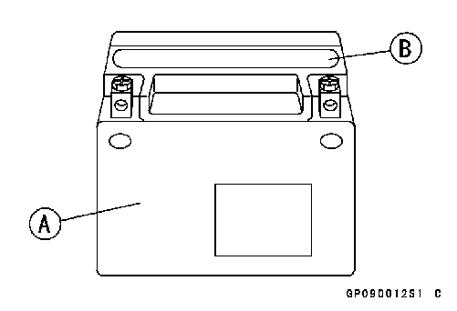 Refreshing Charge
 Terminal Voltage: 11.5 ~ less than 12.8 V
 Terminal Voltage: less than 11.5 V Charging Method 1.2 A × 20 h
 • Remove:
 • Place a suitable container under the alternator cover [A], and remove the cover bolts [B].
 Alternator Cover Installation
 Stator Coil Removal
 Alternator Rotor Removal
 • Using the flywheel puller [A], remove the alternator rotor from the crankshaft.
 Alternator Rotor Installation
 • Install the starter gear [A] and washer [B].
 • Install the alternator rotor [A] while turning [B] it counter- clockwise.
 • Install the washer [A].
 If the rotor is not pulled out with 20 N·m (2.0 kgf·m, 15