Заглавная страница Избранные статьи Случайная статья Познавательные статьи Новые добавления Обратная связь FAQ Написать работу КАТЕГОРИИ: ТОП 10 на сайте Приготовление дезинфицирующих растворов различной концентрацииТехника нижней прямой подачи мяча. Франко-прусская война (причины и последствия) Организация работы процедурного кабинета Смысловое и механическое запоминание, их место и роль в усвоении знаний Коммуникативные барьеры и пути их преодоления Обработка изделий медицинского назначения многократного применения Образцы текста публицистического стиля Четыре типа изменения баланса Задачи с ответами для Всероссийской олимпиады по праву 
Мы поможем в написании ваших работ! ЗНАЕТЕ ЛИ ВЫ?
Влияние общества на человека
Приготовление дезинфицирующих растворов различной концентрации Практические работы по географии для 6 класса Организация работы процедурного кабинета Изменения в неживой природе осенью Уборка процедурного кабинета Сольфеджио. Все правила по сольфеджио Балочные системы. Определение реакций опор и моментов защемления |
Service Limit: 7.3 mm (0.287 in.)Содержание книги
Поиск на нашем сайте
worn dogs or dog holes.
Ball and Needle Bearing Replacement
• Using a press or puller, remove the ball bearing and/or needle bearings. NOTE ○In the absence of the above mentioned tools, satisfac- tory results may be obtained by heating the case to ap- proximately 93°C (200°F) max., and tapping the bearing in or out.
• Using a press and the bearing driver set [A], install the
○The new needle bearings must be pressed into the crankcase so that the end is flush with the end of the hole. Special Tool - Bearing Driver Set: 57001-1129 Ball and Needle Bearing Wear
• Check the ball bearings. ○Since the ball bearings are made to extremely close toler- ances, the wear must be judged by feel rather than mea- surement. Clean each bearing in a high-flash point sol- vent, dry it (do not spin the bearing while it is dry), and oil it with engine oil.
rough spots, replace it. • Check the needle bearings. ○The rollers in a needle bearing normally wear very little, and wear is difficult to measure. Instead of measuring, inspect the bearing for abrasion, color change, or other damage.
Oil Seal Inspection • Inspect the oil seals.
that the rubber has deteriorated), hardened or otherwise damaged.
Wheels/Tires Table of Contents Exploded View........................................................................................................................ 10-2 Specifications......................................................................................................................... 10-4 Special Tools.......................................................................................................................... 10-5 Wheels (Rims)........................................................................................................................ 10-6 Front Wheel Removal....................................................................................................... 10-6 Front Wheel Installation.................................................................................................... 10-6 Rear Wheel Removal........................................................................................................ 10-8 Rear Wheel Installation..................................................................................................... 10-8 Wheel Inspection...................................................................................................................... 10-10 Axle Inspection......................................................................................................................... 10-10 Balance Inspection................................................................................................................... 10-11 Balance Adjustment................................................................................................................. 10-11 Balance Weight Removal........................................................................................................ 10-11 Balance Weight Installation...................................................................................................... 10-11 Tires............................................................................................................................................... 10-13 Air Pressure Inspection/Adjustment......................................................................................... 10-13 Tire Inspection.......................................................................................................................... 10-13 Tire Removal........................................................................................................................... 10-13 Tire Repair............................................................................................................................... 10-15 Hub Bearing................................................................................................................................... 10-16 Hub Bearing Removal.............................................................................................................. 10-16 Hub Bearing Installation........................................................................................................... 10-16 Hub Bearing Inspection............................................................................................................ 10-16 Hub Bearing Lubrication........................................................................................................... 10-17
4. Caliper Bracket (EX650B Models) G: Apply grease. HG: Apply high-temperature grease. R: Replacement Parts WL: Apply soap and water solution or rubber lubricant.
Bearing Remover Shaft,
Jack Attachment: 57001-1608
57001-1293
Front Wheel Removal
Brake Caliper Mounting Bolts [A] Front Brake Calipers [B]
Axle Clamp Bolt [A] • Remove the front axle [B].
• Remove the lower fairings (see Lower Fairing Removal in the Frame chapter). • Raise the front wheel off the ground with jack. Special Tools - Jack: 57001-1238 Jack Attachment: 57001-1608
• Pull out the axle to the right and drop the front wheel out of the forks.
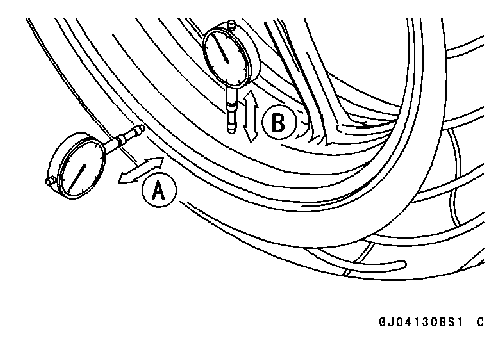
NOTE ○The direction of the wheel rotation [A] is shown by an arrow [B] on the wheel spoke. • Check the wheel rotation mark on the front wheel and install it.
• Apply high-temperature grease to the grease seal lips.
• Insert the front axle, and tighten the axle. Torque - Front Axle: 108 N·m (11.0 kgf·m, 80 ft·lb) • Before tightening the axle clamp bolt on the right front fork leg, pump the front fork up and down 4 or 5 times to allow the right front fork leg to seat on the front axle. NOTE ○Put a block in front of the front wheel to stop moving.
Torque - Front Axle Clamp Bolt: 34 N·m (3.5 kgf·m, 25 ft·lb) • Install the lower fairing (see Lower Fairing Installation in the Frame chapter). • Install the front brake calipers (see Caliper Installation in the Brakes chapter).
• Check the front brake effectiveness (see Brake Operation Inspection in the Periodic Maintenance chapter).
• Raise the rear wheel off the ground with stand [A].
Brake Caliper Mounting Bolts [A] Rear Brake Caliper [B] • Remove the rear wheel rotation sensor from the caliper bracket (see Rear Wheel Rotation Sensor Removal in the Brakes chapter) (EX650B Models).
Axle Nut [B] Washer [C] Axle [D] with Washer
• Apply high-temperature grease to the grease seal lips. • Fit the collars [A] on the both sides of the hub.
• Install the caliper bracket [A] onto the swingarm stop [B]. • Insert the axle from the right side of the wheel, and tighten the axle nut. Torque - Rear Axle Nut: 108 N·m (11.0 kgf·m, 80 ft·lb)
NOTE ○When inserting the cotter pin, if the slots in the nut do not align with the cotter pin hole in the axle, tighten the nut clockwise [B] up to next alignment. ○It should be within 30°. ○Loosen once and tighten again when the slot goes past the nearest hole.
 • Bend the cotter pin [A] over the nut [B]. • Bend the cotter pin [A] over the nut [B].
• Adjust the drive chain slack after installation (see Drive Chain Slack Inspection in the Periodic Maintenance chap- ter). • Install the rear brake caliper (see Caliper Installation in the Brakes chapter). • Install the rear wheel rotation sensor (see Rear Wheel Ro- tation Sensor Installation in the Brakes chapter) (EX650B Models).
• Check the rear brake effectiveness (see Brake Operation Inspection in the Periodic Maintenance chapter).
• Raise the front/rear wheel off the ground with jack.
|
|||||||||||||||||||||||||||||||||||||||||||||||||||||||||||||||||||||||||||||||||||||||||||||||||||||||
|
|
Последнее изменение этой страницы: 2016-08-10; просмотров: 346; Нарушение авторского права страницы; Мы поможем в написании вашей работы! infopedia.su Все материалы представленные на сайте исключительно с целью ознакомления читателями и не преследуют коммерческих целей или нарушение авторских прав. Обратная связь - 3.144.242.149 (0.006 с.) |

 Gear Dog and Gear Dog Hole Damage
 • Visually inspect the gear dogs [A] and gear dog holes [B]. Replace any damaged gears or gears with excessively
 new ball bearing until it stops at the bottom of its housing.
 ○Spin [A] the bearing by hand to check its condition.


 Bearing Driver Set: 57001-1129
 13: 57001-1377
 Jack: 57001-1238
 Bearing Remover Head,
 • Remove:
 • Loosen:
 Front Wheel Installation
 • Fit the collars [A] on the both sides of the hub.
 • Tighten the axle clamp bolt [A].
 Rear Wheel Removal
 • Remove:
 • Remove: Cotter Pin [A]
 • Remove the drive chain [A] from the rear sprocket toward the left.
 Rear Wheel Installation
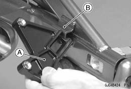 • Engage the drive chain with the rear sprocket.
 • Insert a new cotter pin [A].

 Wheel Inspection