Заглавная страница Избранные статьи Случайная статья Познавательные статьи Новые добавления Обратная связь FAQ Написать работу КАТЕГОРИИ: ТОП 10 на сайте Приготовление дезинфицирующих растворов различной концентрацииТехника нижней прямой подачи мяча. Франко-прусская война (причины и последствия) Организация работы процедурного кабинета Смысловое и механическое запоминание, их место и роль в усвоении знаний Коммуникативные барьеры и пути их преодоления Обработка изделий медицинского назначения многократного применения Образцы текста публицистического стиля Четыре типа изменения баланса Задачи с ответами для Всероссийской олимпиады по праву 
Мы поможем в написании ваших работ! ЗНАЕТЕ ЛИ ВЫ?
Влияние общества на человека
Приготовление дезинфицирующих растворов различной концентрации Практические работы по географии для 6 класса Организация работы процедурного кабинета Изменения в неживой природе осенью Уборка процедурного кабинета Сольфеджио. Все правила по сольфеджио Балочные системы. Определение реакций опор и моментов защемления |
Service Limit: 0.05 mm (0.002 in.)Содержание книги
Поиск на нашем сайте
Valve Clearance Inspection • Refer to the Valve Clearance Inspection in the Periodic Maintenance chapter. Valve Clearance Adjustment • Refer to the Valve Clearance Adjustment in the Periodic Maintenance chapter.
• Remove cylinder head (see Cylinder Head Removal). • Remove the valve lifter and shim. ○Mark and record the valve lifter and shim locations so they can be installed in their original positions. • Using the valve spring compressor assembly, remove the valve. Special Tools - Valve Spring Compressor Assembly [A]: 57001-241 Valve Spring Compressor Adapter,
• Replace the oil seal with a new one. ○Apply engine oil to the oil seal lip. • Apply a thin coat of molybdenum disulfide grease to the valve stem before valve installation. • Install the springs so that the closed coil end faces down- wards (the side painted in green faces upwards). Valve Stem [A] Oil Seal [B] Spring Seat [C] Closed Coil End [D] Valve Spring [E] Side Painted in Green [F] Retainer [G] Split Keepers [H]
• Remove: Valve (see Valve Removal) Oil Seal Spring Seat • Heat the area around the valve guide to 120 ~ 150°C (248 ~ 302°F), and hammer lightly on the valve guide arbor [A]
 to remove the guide from the top of the head. to remove the guide from the top of the head.
Special Tool - Valve Guide Arbor, 4.5: 57001-1331
Valve Guide Installation
• Heat the area around the valve guide hole to about 120 ~ 150°C (248 ~ 302°F). • Drive the valve guide in from the top of the head using the valve guide arbor. The flange stops the guide from going in too far. Special Tool - Valve Guide Arbor, • Wait until the cylinder head cools down and then ream the valve guide with the valve guide reamer [A] even if the old guide is reused. ○Turn the reamer in a clockwise direction until the reamer turns freely in the guide. Never turn the reamer counter- clockwise or it will be dulled. ○Once the guides are reamed they must be cleaned thor- oughly. Special Tool - Valve Guide Reamer,
If a small bore gauge is not available, inspect the valve guide wear by measuring the valve to valve guide clearance with the wobble method as indicated below. • Insert a new valve [A] into the guide [B] and set a dial gauge against the stem perpendicular to it as close as possible to the cylinder head mating surface. • Move the stem back and forth [C] to measure valve/valve guide clearance. • Repeat the measurement in a direction at a right angle to the first.
NOTE ○The reading is not actual valve/valve guide clearance because the measuring point is above the guide. Valve/Valve Guide Clearance (Wobble Method) Standard: Exhaust 0.07 ~ 0.14 mm (0.0028 ~ 0.0055 in.) Inlet 0.02 ~ 0.08 mm (0.0008 ~ 0.0032 in.) Service Limit: Exhaust 0.27 mm (0.0106 in.) Inlet 0.22 mm (0.0087 in.)
• Remove the valve (see Valve Removal). • Check the valve seating surface [A] between the valve [B] and valve seat [C]. ○Measure the outside diameter [D] of the seating pattern on the valve seat.
Valve Seating Surface Outside Diameter Standard: Exhaust 27.6 ~ 27.8 mm (1.087 ~ 1.094 in.) Inlet 32.6 ~ 32.8 mm (1.283 ~ 1.291 in.) ○Measure the seat width [E] of the portion where there is no build-up carbon (white portion) of the valve seat with a vernier caliper. Good [F]
Valve Seating Surface Width Standard: Exhaust 0.5 ~ 1.0 mm (0.020 ~ 0.039 in.) Inlet 0.5 ~ 1.0 mm (0.020 ~ 0.039 in.)
• Repair the valve seat with the valve seat cutters [A]. Special Tools - Valve Seat Cutter Holder Bar [C]: 57001-1128 Valve Seat Cutter Holder, For Exhaust Valve Seat Valve Seat Cutter, 45° - Valve Seat Cutter, 32° - Valve Seat Cutter, 60° - For Inlet Valve Seat Valve Seat Cutter, 45° - Valve Seat Cutter, 32° - Valve Seat Cutter, 55° -
Seat Cutter Operation Care 1. This valve seat cutter is developed to grind the valve for repair. Therefore the cutter must not be used for other purposes than seat repair. 2. Do not drop or shock the valve seat cutter, or the dia- mond particles may fall off. 3. Do not fail to apply engine oil to the valve seat cutter before grinding the seat surface. Also wash off ground particles sticking to the cutter with washing oil. NOTE ○Do not use a wire brush to remove the metal particles from the cutter. It will take off the diamond particles. 4. Setting the valve seat cutter holder in position, operate the cutter in one hand. Do not apply too much force to the diamond portion. NOTE ○Prior to grinding, apply engine oil to the cutter and dur- ing the operation, wash off any ground particles sticking to the cutter with washing oil. 5. After use, wash it with washing oil and apply thin layer of engine oil before storing.
The marks stamped on the back of the cutter [A] represent the following. 60°........................... Cutter angle [B]
Operating Procedures • Clean the seat area carefully. • Coat the seat with machinist’s dye. • Fit a 45° cutter into the holder and slide it into the valve guide.
• Press down lightly on the handle and turn it right or left. Grind the seating surface only until it is smooth.
Widened Width [A] of engagement by machining with 45° cutter Ground Volume [B] by 32° cutter 32° [C] Correct Width [D] Ground Volume [E] by 60° or 55° cutter 60° or 55° [F]
Original Seating Surface [B] NOTE ○Remove all pittings of flaws from 45° ground surface. ○After grinding with 45° cutter, apply thin coat of machin- ist’s dye to seating surface. This makes seating surface distinct and 32° and 60° (or 55°) grinding operation eas- ier. ○When the valve guide is replaced, be sure to grind with 45° cutter for centering and good contact.
• Grind the seat at a 32° angle [B] until the seat outside diameter is within the specified range. ○To make the 32° grind, fit a 32° cutter into the holder, and slide it into the valve guide. ○Turn the holder one turn at a time while pressing down
very lightly. Check the seat after each turn. ○After making the 32° grind, return to the seat outside di- ameter measurement step above. • To measure the seat width, use a vernier caliper to mea- sure the width of the 45° angle portion of the seat at sev- eral places around the seat.
• Grind the seat at a 60° or 55° angle until the seat width is within the specified range. ○To make the 60° or 55° grind, fit 60° or 55° cutter into the holder, and slide it into the valve guide. ○Turn the holder, while pressing down lightly. ○After making the 60° or 55° grind, return to the seat width measurement step above. Correct Width [B]
○Put a little coarse grinding compound on the face of the valve in a number of places around the valve head. ○Spin the valve against the seat until the grinding com- pound produces a smooth, matched surface on both the seat and the valve. ○Repeat the process with a fine grinding compound. Lapper [A] Valve Seat [B] Valve [C] • The seating area should be marked about in the middle of the valve face.
• Be sure to remove all grinding compound before assem- bly. • When the engine is assembled, be sure to adjust the valve clearance (see Valve Clearance Adjustment in the Peri- odic Maintenance chapter).
Cylinder Removal
Cylinder Head (see Cylinder Head Removal) Front Engine Mounting Bolts (Both Side) [A] (see Engine Removal in the Engine Removal/Installation chapter) Front Engine Brackets (Both Side) [B] (see Engine Re- moval in the Engine Removal/Installation chapter) Cylinder [C]
NOTE ○If a new cylinder is used, use new piston ring. • Install the dowel pins [A] and new cylinder gasket [B].
about 30 ~ 40° of angle from the opening of the top ring. Top Ring [A] Second Ring [B] Oil Ring Steel Rails [C] Oil Ring Expander [D] Hollow [E] 30 ~ 40° [F]
• Prepare two auxiliary head bolts with their head cut. ○Install the two bolts [A] diagonally in the crankcase. • Position the crankshaft so that all the piston heads are almost level. • Install the cylinder block. ○Insert the piston rings with your thumbs.
• Remove the cylinder (see Cylinder Removal). • Place a clean cloth under the pistons and remove the pis- ton pin snap ring [A] from the outside of each piston.
• Remove the piston pins.
Piston Pin Puller Adapter C [D]: 57001-1657 Center Bolt [B] Shall of Piston [C] • Remove the pistons.
it. • Remove the 3-piece oil ring with your thumbs in the same manner.
• Install the oil ring expander [A] in the bottom piston ring groove so the ends [B] butt together. • Install the oil ring steel rails, one above the expander and one below it. ○Spread the rail with your thumbs, but only enough to fit the rail over the piston. ○Release the rail into the bottom piston ring groove. NOTE ○The oil ring rails have no “top” or “bottom”.
• Install the top ring [A] so that the "R" mark [B] faces up. • Install the second ring [C] so that the "RN" mark [D] faces up.
○If a new piston is used, use new piston ring. • Install the piston with its marking hollow facing forward. • Fit a new piston pin snap ring into the side of the piston so that the ring opening [A] does not coincide with the slit [B] of the piston pin hole. ○Apply molybdenum disulfide oil solution to the piston pins and piston journals. ○When installing the piston pin snap ring, compress it only
enough to install it and no more. • Install the cylinder (see Cylinder Installation).
• Since there is a difference in cylinder wear in different di- rections, take a side-to-side and a front-to-back measure- ment at each of the two locations (total of four measure- ments) shown in the figure.
10 mm (0.39 in.) [A] 60 mm (2.36 in.) [B] Cylinder Inside Diameter Standard: 82.994 ~ 83.006 mm (3.2675 ~ 3.2679 in.)
|
||||||||||
|
|
Последнее изменение этой страницы: 2016-08-10; просмотров: 467; Нарушение авторского права страницы; Мы поможем в написании вашей работы! infopedia.su Все материалы представленные на сайте исключительно с целью ознакомления читателями и не преследуют коммерческих целей или нарушение авторских прав. Обратная связь - 216.73.216.20 (0.007 с.) |

 If the cylinder head is warped more than the service limit, replace it.
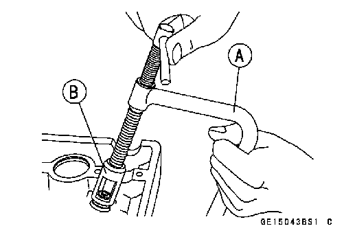 Valve Removal
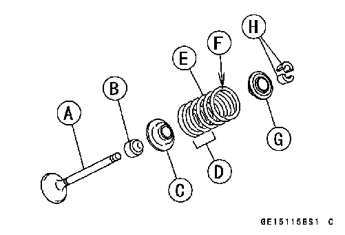 Valve Installation
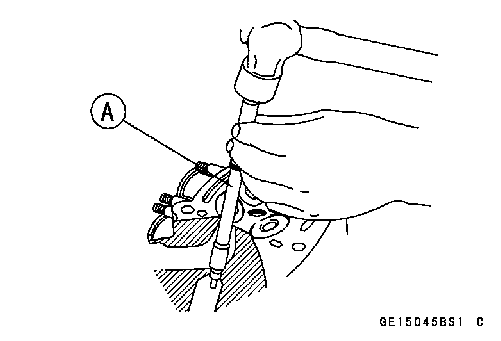 Valve Guide Removal
 • Apply engine oil to the valve guide outer surface before installation.
 4.5: 57001-1331
 Valve-to-Guide Clearance Measurement (Wobble Method)
 Valve Seat Inspection
 Valve Seat Repair
 Marks Stamped on the Cutter
 37.5....................... Outer diameter of cutter [C]
 • Measure the outside diameter of the seating surface with a vernier caliper.
 • Measure the outside diameter of the seating surface with a vernier caliper.
 If the outside diameter [A] of the seating surface is too large, make the 32° grind described below.
 If the seat width is too wide, make the 60° or 55° [A] grind described below.
 • Lap the valve to the seat, once the seat width and outside diameter are within the ranges specified above.
 • Remove:
 Cylinder Installation
 • The piston ring openings must be positioned as shown in the figure. The openings of the oil ring steel rails must be
 • Apply molybdenum disulfide oil solution to the cylinder bore, piston rings and piston.
 Piston Removal
 Special Tools - Piston Pin Puller [A]: 57001-1568
 • Carefully spread the ring opening with your thumbs and then push up on the opposite side of the ring [A] to remove
 Piston Installation
 • Do not mix up the top and second ring.
 NOTE
NOTE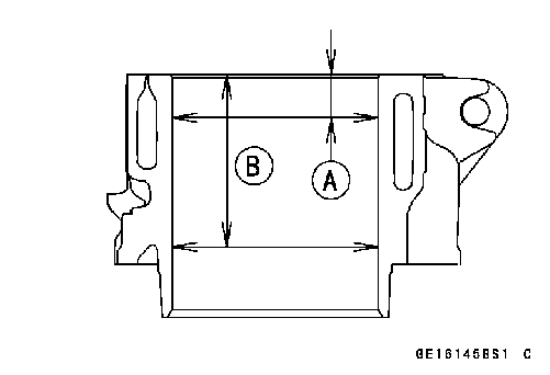 Cylinder Wear