Заглавная страница Избранные статьи Случайная статья Познавательные статьи Новые добавления Обратная связь FAQ Написать работу КАТЕГОРИИ: ТОП 10 на сайте Приготовление дезинфицирующих растворов различной концентрацииТехника нижней прямой подачи мяча. Франко-прусская война (причины и последствия) Организация работы процедурного кабинета Смысловое и механическое запоминание, их место и роль в усвоении знаний Коммуникативные барьеры и пути их преодоления Обработка изделий медицинского назначения многократного применения Образцы текста публицистического стиля Четыре типа изменения баланса Задачи с ответами для Всероссийской олимпиады по праву 
Мы поможем в написании ваших работ! ЗНАЕТЕ ЛИ ВЫ?
Влияние общества на человека
Приготовление дезинфицирующих растворов различной концентрации Практические работы по географии для 6 класса Организация работы процедурного кабинета Изменения в неживой природе осенью Уборка процедурного кабинета Сольфеджио. Все правила по сольфеджио Балочные системы. Определение реакций опор и моментов защемления |
Special Tools - Bearing Driver Set: 57001-1129Содержание книги
Поиск на нашем сайте
Stem Bearing Driver,
• Install the needle bearings [A], ball bearing [B] and oil seals [C] position as shown. Circlip [D] 25 mm (0.98 in.) [E] 17 mm (0.67 in.) [F] 1 mm (0.04 in.) [G] 0.5 mm (0.02 in.) [H] 1 mm (0.04 in.) [I] 23.5 mm (0.93 in.) [J]
• Inspect the needle bearings [A] and ball bearing installed in the swingarm. ○The rollers and ball in a bearing normally wear very little, and wear is difficult to measure. Instead of measuring, visually inspect the bearing for abrasion, discoloration, or other damage.
• Examine the bearing seal [B] for tears or leakage.
Swingarm Bearing Lubrication NOTE ○Since the bearings are packed with grease and sealed, lubrication is not required. Chain Guide Inspection • Refer to the Chain Guide Wear Inspection in the Periodic Maintenance chapter.
Steering Table of Contents Exploded View........................................................................................................................ 14-2 Special Tools.......................................................................................................................... 14-4 Steering.................................................................................................................................. 14-5 Steering Inspection........................................................................................................... 14-5 Steering Adjustment.......................................................................................................... 14-5 Steering Stem......................................................................................................................... 14-6 Stem, Stem Bearing Removal........................................................................................... 14-6 Stem, Stem Bearing Installation........................................................................................ 14-7 Stem Bearing Lubrication.................................................................................................. 14-9 Steering Stem Warp.......................................................................................................... 14-9 Stem Cap Deterioration, Damage..................................................................................... 14-9 Handlebar...................................................................................................................................... 14-10 Handlebar Removal................................................................................................................. 14-10 Handlebar Installation............................................................................................................... 14-10
14
AD: Apply adhesive. AL: Tighten the two clamp bolts alternately two times to ensure even tighten torque. G: Apply grease. L: Apply a non-permanent locking agent. R: Replacement Parts S: Follow the specified tightening sequence.
Steering Stem Bearing Driver,
Steering Stem Bearing Driver Adapter,
Steering Inspection • Refer to the Steering Play Inspection in the Periodic Main- tenance chapter. Steering Adjustment • Refer to the Steering Play Adjustment in the Periodic Maintenance chapter.
Stem, Stem Bearing Removal
Upper Fairing (see Upper Fairing Removal in the Frame chapter) Under Bracket [A] (see Upper Fairing Bracket Removal in the Frame chapter)
Upper Fairing Bracket [A] (see Upper Fairing Bracket Removal in the Frame chapter)
Front Wheel (see Front Wheel Removal in the Wheels/Tires chapter) Front Forks (see Front Fork Removal in the Suspension chapter) Handlebar (see Handlebar Removal) Steering Stem Head Bolt Plug [A] Steering Stem Head Bolt [B] and Washer Front Fork Clamp Bolts (Upper) [C] (Loosen) Steering Stem Head [D]
• Remove the steering stem locknut [B] and claw washer [C].
Special Tool - Steering Stem Nut Wrench [C]: 57001-1100 • Remove the steering stem [D] under side. • Remove the upper stem bearing inner race and bearing.
• To remove the bearing outer races [A] pressed into the head pipe [B], insert a bar [C] into the recesses of head
NOTE ○If either steering stem bearing is damaged, it is recom- mended that both the upper and lower bearings (includ- ing outer races) should be replaced with new ones.
able chisel [B].
• Replace the bearing outer races with new ones. • Apply grease to the outer races, and drive them into the head pipe at the same time. Special Tool - Bearing Driver Set [A]: 57001-1129
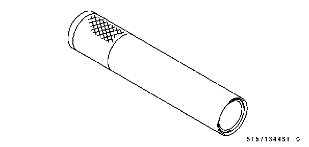
• Apply grease to the oil seal. • Drive the lower ball bearing inner race applied the grease onto the stem. Special Tools - Steering Stem Bearing Driver, 57001-1344 Steering Stem Bearing Driver Adapter,
• Apply grease to the upper ball bearing [B] and inner race [C].
• Install the stem cap [D] and steering stem nut [E].
○Tighten the steering stem nut with 39 N·m (4.0 kgf·m, 29 ft·lb) of torque first, and loosen it a fraction of a turn until it turns lightly. Afterward tighten it again with specified torque using a stem nut wrench [A] in the direction shown. ○Check that there is no play and the steering stem turns smoothly without rattles. If not, the steering stem bearings may be damaged.
• Install the claw washer [A] so that its bent side [B] faces upward, and engage the bent claws with the grooves of stem locknut [C]. • Hand tighten the stem locknut until it touches the claw washer. • Tighten the stem locknut clockwise until the claws are aligned with the grooves (ranging from 2nd to 4th) of stem nut [D], and bend the 2 claws downward [E]. • Install the stem head. • Install the washer, and tighten the stem head bolt with specified torque. • Install the front forks (see Front Fork Installation in the Suspension chapter).
NOTE ○Tighten the upper fork clamp bolts first, next the stem head bolt, last the lower fork clamp bolts. ○Tighten the two clamp bolts alternately two times to en- sure even tightening torque. Torque - Front Fork Clamp Bolts (Upper): 20 N·m (2.0 kgf·m, 15 ft·lb) Steering Stem Head Bolt: 108 N·m (11.0 kgf·m, 80 ft·lb)
Front Fork Clamp Bolts (Lower): 20 N·m (2.0 kgf·m, 15 ft·lb) • Install the steering stem head bolt plug. • Install the removed parts (see appropriate chapters).
Stem Bearing Lubrication • Refer to the Steering Stem Bearing Lubrication in the Pe- riodic Maintenance chapter.
• Whenever the steering stem is removed, or if the steering cannot be adjusted for smooth action, check the steering stem for straightness.
Handlebar Removal
Clutch Lever Assembly [A] Left Switch Housing [B] Left Handlebar Weight [C]
Front Brake Master Cylinder [A] (see Front Master Cylin- der Removal in the Brakes chapter) Right Switch Housing [B] Right Handlebar Weight [C] Throttle Grip [D]
• Remove the handlebar holder [B] and then pull out the handlebar.
• Align the punch mark [A] on the handlebar and the corner edge [B] on the stem head.
dlebar holder after tightening. Torque - Handlebar Holder Bolts: 25 N·m (2.5 kgf·m, 18 ft·lb)
• Install the clutch lever (see Clutch Lever Installation in the Clutch chapter). • Apply adhesive cement to the inside of the left handlebar grip. • Apply a non-permanent locking agent to the left handlebar weight bolt. • Install the left switch housing. ○Fit the projection [A] into a small hole [B] in the handlebar. Torque - Left Switch Housing Screws: 3.5 N·m (0.36 kgf·m, 31 in·lb)
Throttle Grip Throttle Cable Tips [A] Right Switch Housing ○Fit the projection [B] into a small hole [C] in the handlebar. Torque - Right Switch Housing Screws: 3.5 N·m (0.36 kgf·m, 31 in·lb) • Apply a non-permanent locking agent to the right handle- bar weight bolt. • Install the front brake master cylinder (see Front Master Cylinder Installation in the Brakes chapter).
Frame Table of Contents Exploded View........................................................................................................................ 15-2 Seat........................................................................................................................................ 15-8 Seat Removal................................................................................................................... 15-8 Seat Installation................................................................................................................ 15-8 Fairings................................................................................................................................... 15-9 Lower Fairing Removal..................................................................................................... 15-9 Lower Fairing Installation.................................................................................................. 15-9 Center Fairing Removal.................................................................................................... 15-9 Center Fairing Installation................................................................................................. 15-9 Windshield Removal................................................................................................................ 15-10 Windshield Installation.............................................................................................................. 15-10 Upper Fairing Removal............................................................................................................ 15-10 Upper Fairing Disassembly...................................................................................................... 15-11 Upper Fairing Assembly........................................................................................................... 15-11 Upper Fairing Installation.......................................................................................................... 15-11 Upper Inner Fairing Removal................................................................................................... 15-11 Upper Inner Fairing Installation................................................................................................ 15-11 Upper Fairing Bracket Removal.............................................................................................. 15-11 Inner Fairing Removal.............................................................................................................. 15-12 Inner Fairing Installation........................................................................................................... 15-12 Side Covers................................................................................................................................... 15-13 Side Cover Removal................................................................................................................ 15-13 Side Cover Installation............................................................................................................. 15-13 Seat Covers................................................................................................................................... 15-14 Seat Cover Removal............................................................................................................... 15-14 Seat Cover Installation............................................................................................................. 15-14 Fenders.......................................................................................................................................... 15-15 Front Fender Removal............................................................................................................. 15-15 Front Fender Installation........................................................................................................... 15-15 Flap and Rear Fender Rear Installation................................................................................... 15-15 Rear Fender Front Removal.................................................................................................... 15-16 Rear Fender Front Installation.................................................................................................. 15-16 Frame............................................................................................................................................ 15-17 Frame Inspection..................................................................................................................... 15-17 Sidestand....................................................................................................................................... 15-18 Sidestand Removal.................................................................................................................. 15-18 Sidestand Installation............................................................................................................... 15-18 Frame Cover................................................................................................................................. 15-19 Frame Cover Removal............................................................................................................ 15-19 Frame Cover Installation.......................................................................................................... 15-19
4. EX650B Models 5. EX650A Models G: Apply grease. L: Apply a non-permanent locking agent. R: Replacement Parts
L: Apply a non-permanent locking agent.
3. Seat (United States and Canada Models) 4. Seat Lock Bracket (EX650B Models) 5. EX650B Models 6. Grab Rails (Other than United States and Canada Models) 7. Washers (United States and Canada Models)
Seat Removal
and pulling the seat backward.
• Slip the seat hook [A] under the brace [B] on the fuel tank bracket.
• Push down the rear part of the seat until the lock clicks.
Lower Fairing Removal
• Remove the quick rivets [A]. • Remove the bolts [B] with collar and washers. • Clear the hook portions from the slots. • Separate the left lower fairing from the right lower fairing.
• Insert the hook portions [A] into the slots [B]. • Set the quick rivet and push the core.
• Remove: Lower Fairings (see Lower Fairing Removal) Upper Inner Fairing (see Upper Inner Fairing Removal) Screw [A] Bolt [B] with Washers
• Disconnect the turn signal lead connector [A]. • Remove the screw [B]. • Pull the center fairing [C] evenly outward to clear the stop- pers.
• Remove the screw [A] and turn signal light [B].
Center Fairing Installation • Install the turn signal light to the center fairing. • Install the inner fairing (see Inner Fairing Installation).
• Insert the hook [A] into the slot [B].
• Connect the turn signal lead connector. • Install the bolt and screws.
• Remove: Bolts [A] with Washers Windshield [B] Dampers
• Install the dampers. • Insert the hook [A] into the slot [B]. • Tighten the bolts with washers.
• Remove: Windshield (see Windshield Removal) Upper Inner Fairings (see Upper Inner Fairing Removal) Lower Fairings (see Lower Fairing Removal) Center Fairings (see Center Fairing Removal) Headlight Lead Connectors Rear View Mirror Nuts (Both Side) [A] • Remove the upper fairing forward.
• Remove: Headlight [A] (see Headlight Removal/Installation in the Electrical System chapter)
Upper Fairing Assembly • Install the headlight (see Headlight Removal/Installation in the Electrical System chapter). Upper Fairing Installation • Installation is the reverse of removal.
• Remove the bolts [A]. • Pull the upper inner fairing [B] backward, and clear the hooks.
• Insert the hook [A] into the slot [B]. • Tighten the bolts.
• Remove: Upper Fairing (see Upper Fairing Removal) Meter Unit (see Meter Unit Removal/Installation in the Electrical System chapter) Clamp [A] Bolts [B] Horn Leads [C] Under Bracket [D]
Clamps [B] Upper Fairing Bracket [C]
• Remove: Center Fairings (see Center Fairing Removal) Mounting Screws [A] Inner Fairing [B]
Inner Fairing Installation • Tighten the mounting screws. Torque - Front Turn Signal Light Mounting Screws: 1.2 N·m (0.12 kgf·m, 11 in·lb) • Install the center fairings (see Center Fairing Installation).
Side Cover Removal
• Remove the bolt [A]. • Pull the side cover [B] evenly outward to clear the stop- pers.
• Insert the tabs [A] into the holes [B]. • Tighten the bolt. • Install the seat (see Seat Installation).
Seat Cover Removal
Seat (see Seat Removal) Bolts [A] Grab Rails [B] (Other than United States and Canada Models) Screw Rivets [C]
• Pull the front and rear portions of the seat cover outside, and then remove the seat covers.
• Installation is the reverse of removal. • Put the projection [A] into the grommet [B] on the rear fender rear.
• Install: Grab Rails (Other than United States and Canada Mod- els) and Bolts Torque - Grab Rail Mounting Bolts: 25 N·m (2.5 kgf·m, 18 ft·lb)
• Install: Screw Rivets Seat (see Seat Installation)
Front Fender Removal
Brake Hose Clamps [A] Bolts [B] with Collar (Both Side) • Remove the front fender [C].
Front Fender Installation • Tighten: Torque - Front Fender Bolts: 3.9 N·m (0.40 kgf·m, 35 in·lb) • Install the brake hose clamps to the front fender holes.
• Remove: Seat (see Seat Removal) Seat Covers (see Seat Cover Removal) Tail/Brake Light [A] (see Tail/Brake Light Removal in the Electrical System chapter)
Nuts [A] and Bolts [B] Flap (with License Plate Light)
Seat Lock Cable Lower End [A] Quick Rivet [B] • Free the clamps from the rear fender rear. • Pull out the rear fender rear backward and downward.
Flap and Rear Fender Rear Installation • Installation is the reverse of removal.
Rear Fender Front Removal
Rear Fender Rear (see Flap and Rear Fender Rear Re- moval) Battery (see Battery Removal in the Electrical System chapter) Relay Box (see Relay Box Removal in the Electrical Sys- tem chapter) Starter Relay (see Starter Relay Inspection in the Elec- trical System chapter) • Remove the fuse box from the rear fender front. • Remove: Bolt [A] Clamp [B]
• Remove the rear fender front [A] backward and upward.
Rear Fender Front Installation • Installation is the reverse of removal. • Install the removed parts (see appropriate chapters).
Frame Inspection • Visually inspect the frame for cracks, dents, bending or warp. ○If there is any damage to the frame, replace it.
Sidestand Removal
• Remove: Frame Cover (see Frame Cover Removal) Bolts [A] Footpeg Stay [B]
Sidestand Switch Bolt [A] with Clamp Sidestand Switch [B]
Sidestand Nut [B] Sidestand Bolt [C] Sidestand [D]
• Apply grease to the sliding area [A] of the sidestand [B]. • Tighten the bolt and lock them with the nut. Torque - Sidestand Bolt: 44 N·m (4.5 kgf·m, 33 ft·lb) • Hook the spring. • Install the sidestand switch. ○Apply a non-permanent locking agent to the thread of the switch bolt. Torque - Sidestand Switch Bolt: 8.8 N·m (0.90 kgf·m, 78 in·lb) • Install the footpeg stay. • Tighten: Torque - Footpeg Stay Bolts: 34 N·m (3.5 kgf·m, 25 ft·lb)
Frame Cover Removal
• Pull the frame cover [B] outward to clear the stoppers.
• Insert the projections [A] into the holes [B]. • Tighten the bolt.
Electrical System Table of Contents Exploded View........................................................................................................................ 16-3 Specifications................................................................................................................................ 16-10 Special Tools and Sealants........................................................................................................... 16-11 Parts Location................................................................................................................................ 16-12 Wiring Diagram (Europe, Korea, Hong Kong and Kuwait)............................................................ 16-14 Wiring Diagram (United States, Canada, New Zealand and Malaysia)........................................ 16-16 Wiring Diagram (Australia and South Africa)................................................................................ 16-18 Wiring Diagram (EX650B Models)................................................................................................ 16-20 Precautions.................................................................................................................................... 16-22 Electrical Wiring............................................................................................................................. 16-24 Wiring Inspection...................................................................................................................... 16-24 Battery........................................................................................................................................... 16-25 Battery Removal...................................................................................................................... 16-25 Battery Installation.................................................................................................................... 16-25 Battery Activation..................................................................................................................... 16-25 Precautions.............................................................................................................................. 16-28 Interchange.............................................................................................................................. 16-28 Charging Condition Inspection................................................................................................. 16-29 Refreshing Charge................................................................................................................... 16-29 Charging System........................................................................................................................... 16-31 Alternator Cover Removal....................................................................................................... 16-31 Alternator Cover Installation..................................................................................................... 16-31 Stator Coil Removal................................................................................................................. 16-31 Stator Coil Installation.............................................................................................................. 16-32 Alternator Rotor Removal........................................................................................................ 16-32 Alternator Rotor Installation...................................................................................................... 16-32 Alternator Inspection................................................................................................................ 16-34 Regulator/Rectifier Inspection.................................................................................................. 16-35 Charging Voltage Inspection.................................................................................................... 16-38 Starter Motor Clutch...................................................................................................................... 16-40 Starter Motor Clutch Removal/Installation............................................................................... 16-40 Starter Motor Clutch Inspection........................................................................................ 16-40 16 Starter Motor Clutch Disassembly........................................................................................... 16-40 Starter Motor Clutch Assembly................................................................................................ 16-40 Ignition System.............................................................................................................................. 16-41 Crankshaft Sensor Removal................................................................................................... 16-41 Crankshaft Sensor Installation................................................................................................. 16-42 Crankshaft Sensor Inspection.................................................................................................. 16-42 Crankshaft Sensor Peak Voltage Inspection........................................................................... 16-42 Timing Rotor Removal............................................................................................................. 16-43 Timing Rotor Installation........................................................................................................... 16-43 Stick Coil (Ignition Coil together with Spark Plug Cap) Removal............................................ 16-43 Stick Coil (Ignition Coil together with Spark Plug Cap) Installation......................................... 16-43 Stick Coil (Ignition Coil together with Spark Plug Cap) Inspection.......................................... 16-44 Stick Coil Primary Peak Voltage............................................................................................. 16-44 Spark Plug Removal................................................................................................................ 16-45 Spark Plug Installation............................................................................................................. 16-45 Spark Plug Condition Inspection.............................................................................................. 16-45 Interlock Operation Inspection................................................................................................. 16-45 IC Igniter Inspection................................................................................................................. 16-46 Electric Starter System................................................................................................................. 16-49 Starter Motor Removal............................................................................................................ 16-49 Starter Motor Installation.......................................................................................................... 16-49 Starter Motor Disassembly...................................................................................................... 16-50 Starter Motor Assembly........................................................................................................... 16-50 Brush Inspection...................................................................................................................... 16-51 Commutator Cleaning and Inspection..................................................................................... 16-51 Armature Inspection................................................................................................................. 16-52 Brush Lead Inspection............................................................................................................. 16-52 Brush Plate and Terminal Bolt Inspection................................................................................ 16-52 Starter Relay Inspection.......................................................................................................... 16-53 Lighting System............................................................................................................................. 16-55 Headlight Beam Horizontal Adjustment................................................................................... 16-55 Headlight Beam Vertical Adjustment....................................................................................... 16-55 Headlight Bulb Replacement................................................................................................... 16-55 City Light Bulb Replacement (Europe Models)....................................................................... 16-56 Headlight Removal/Installation................................................................................................ 16-56 Tail/Brake Light Removal........................................................................................................ 16-56 Tail/Brake Light Installation...................................................................................................... 16-56 License Plate Light Bulb Replacement.................................................................................... 16-57 Turn Signal Light Bulb Replacement....................................................................................... 16-58 Turn Signal Relay Inspection................................................................................................... 16-59 Air Switching Valve........................................................................................................................ 16-61 Air Switching Valve Operation Test......................................................................................... 16-61 Air Switching Valve Unit Test.................................................................................................. 16-61 Radiator Fan System..................................................................................................................... 16-63 Fan Motor Inspection............................................................................................................... 16-63 Meter, Gauge, Indicator Unit......................................................................................................... 16-64 Meter Unit Removal/Installation............................................................................................... 16-64 Meter, Gauge Disassembly..................................................................................................... 16-64 Electronic Combination Meter Unit Inspection........................................................................ 16-65 Switches and Sensors................................................................................................................... 16-73 Brake Light Timing Inspection................................................................................................. 16-73 Brake Light Timing Adjustment................................................................................................ 16-73 Switch Inspection..................................................................................................................... 16-73 Water Temperature Sensor Inspection.................................................................................... 16-74 Speed Sensor Removal........................................................................................................... 16-74 Speed Sensor Installation........................................................................................................ 16-74 Speed Sensor Inspection......................................................................................................... 16-75 Oxygen Sensor Removal (Europe Models)............................................................................ 16-75 Oxygen Sensor Installation (Europe Models).......................................................................... 16-75 Oxygen Sensor Inspection (Europe Models).......................................................................... 16-76 Fuel Reserve Switch Inspection.............................................................................................. 16-76 Relay Box...................................................................................................................................... 16-77 Relay Box Removal................................................................................................................. 16-77 Relay Circuit Inspection........................................................................................................... 16-77 Diode Circuit Inspection........................................................................................................... 16-78 Fuse............................................................................................................................................... 16-80 30 A Main Fuse Removal........................................................................................................ 16-80 Fuse Box Fuse Removal......................................................................................................... 16-80 15 A ECU Fuse Removal........................................................................................................ 16-80 Fuse Installation....................................................................................................................... 16-81 Fuse Inspection........................................................................................................................ 16-81 Dummy Page
5. Meter Unit (EX650B Models) 6. City Light (Europe Models)
9. Main Harness (EX650B Models) G: Apply grease. L: Apply a non-permanent locking agent. R: Replacement Parts
16. EX650B Models 17. EX650A Models L: Apply a non-permanent locking agent. M: Apply molybdenum disulfide grease. MO: Apply molybdenum disulfide oil solution. (Mixture of the engine oil and molybdenum disulfide grease in a weight ratio 10: 1) R: Replacement Parts SS: Apply silicone sealant.
Grip: 57001-1591
Flywheel & Pulley Holder: 57001-1605
Rotor Holder: 57001-1658
|
|||||||||||||||||||||||||||||||||||||||||||||||||||||||||||||||||||||||||||||||||||||||||||||||||||||||||||||||||||||||||||||||||||||||||||||||||||||||||||||||||||||||||||||||||||||||||||||||||||||||||||||||||||||||||||||||||||||||||||||||||||||||||||||||||||||||||||||||||||||||||||||||||||||||||||||||||||||||||||||||||||||||||||||||||||||||||
|
|
Последнее изменение этой страницы: 2016-08-10; просмотров: 648; Нарушение авторского права страницы; Мы поможем в написании вашей работы! infopedia.su Все материалы представленные на сайте исключительно с целью ознакомления читателями и не преследуют коммерческих целей или нарушение авторских прав. Обратная связь - 18.117.101.250 (0.025 с.) |

 28 [B]: 57001-1610
 Spacer, 28: 57001-1663
 Swingarm Bearing, Sleeve Inspection
 If the needle bearing and sleeve [B] show any sings of abnormal wear, discoloration, or damage, replace them as a set.
 • Turn the bearing in the swingarm back and forth [A] while checking for plays, roughness, or binding.
 If the bearing play, roughness, or binding is found, replace the bearing.

 Steering Stem Nut Wrench: 57001-1100
 Bearing Driver Set: 57001-1129
 • Remove:
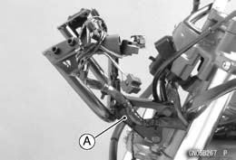 • Remove:
 • Remove:
 • Bend the claws [A] of the claw washer straighten.
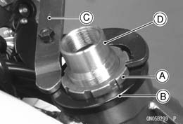 • Pushing up the stem base, and remove the steering stem nut [A] with stem cap [B].
 pipe, and applying it to both recess alternately hammer it to drive the race out.
 • Remove the lower bearing inner race [A] which is pressed onto the steering stem with a suitable commercially avail-
 Stem, Stem Bearing Installation
 • Replace the bearing inner races and oil seal with new ones.
 • Apply grease to the lower ball bearing [A], and install it onto the stem.
 • Install the stem [A] through the head pipe and install the ball bearing [B] and inner race [C] on it.
 • Settle the inner races in place as follows.
 Special Tool - Steering Stem Nut Wrench: 57001-1100 Torque - Steering Stem Nut: 20 N·m (2.0 kgf·m, 15 ft·lb)
 Steering Stem Warp
 Stem Cap Deterioration, Damage
 • Remove:
 • Remove:
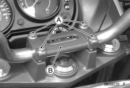 • Remove the handlebar holder bolts [A].
 Handlebar Installation
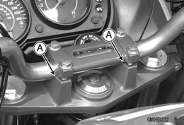 • Tighten the front holder bolts first, and then the rear holder bolts. There will be a gap [A] at the rear part of the han-
 Handlebar
 • Install:


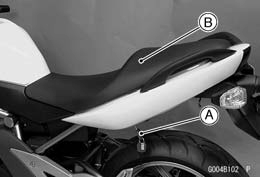 • Insert the ignition switch key [A] into the seat lock, turning the key clockwise, pulling up on the rear of the seat [B],
 Seat Installation
 • Insert the seat latch [A] into the latch hole [B].
 • Pull up the core by the thin blade driver.
 Lower Fairing Installation
 Center Fairing Removal
 • Remove the meter cover (see Meter Unit Removal/Instal- lation in the Electrical System chapter).
 • Remove the inner fairing (see Inner Fairing Removal).
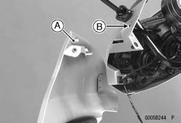
 • Insert the projection [A] into the hole [B].
 Windshield Removal
 Windshield Installation
 Upper Fairing Removal
 Upper Fairing Disassembly
 Upper Inner Fairing Removal
 Upper Inner Fairing Installation
 Upper Fairing Bracket Removal
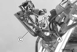 • Remove: Bolts [A]
 Inner Fairing Removal
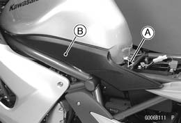 • Remove the seat (see Seat Removal).
 Side Cover Installation
 • Remove:
 • Push the central pin, and then remove the quick rivets [A].
 Seat Cover Installation
 • Put the projection [A] into the hole [B] of the seat cover.
 • Insert the projections [A] of the center seat cover into the holes [B] of the side seat cover.
 • Remove:
 Flap and Rear Fender Rear Removal
 • Remove:
 • Remove:
 • Remove:
 • Free the clamp from the rear fender front.
 • Raise the rear wheel off the ground with stand.
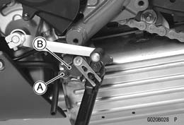 • Remove:
 • Remove: Spring [A]
 Sidestand Installation
 • Remove the bolt [A].
 Frame Cover Installation


 Hand Tester: 57001-1394
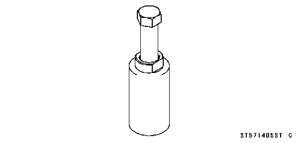
 Flywheel Puller Assembly, M38 × 1.5/M35 × 1.5: 57001-1405
 Peak Voltage Adapter: 57001-1415