Заглавная страница Избранные статьи Случайная статья Познавательные статьи Новые добавления Обратная связь FAQ Написать работу КАТЕГОРИИ: ТОП 10 на сайте Приготовление дезинфицирующих растворов различной концентрацииТехника нижней прямой подачи мяча. Франко-прусская война (причины и последствия) Организация работы процедурного кабинета Смысловое и механическое запоминание, их место и роль в усвоении знаний Коммуникативные барьеры и пути их преодоления Обработка изделий медицинского назначения многократного применения Образцы текста публицистического стиля Четыре типа изменения баланса Задачи с ответами для Всероссийской олимпиады по праву 
Мы поможем в написании ваших работ! ЗНАЕТЕ ЛИ ВЫ?
Влияние общества на человека
Приготовление дезинфицирующих растворов различной концентрации Практические работы по географии для 6 класса Организация работы процедурного кабинета Изменения в неживой природе осенью Уборка процедурного кабинета Сольфеджио. Все правила по сольфеджио Балочные системы. Определение реакций опор и моментов защемления |
Injector Resistance Connections to InjectorСодержание книги
Поиск на нашем сайте
Meter (+) Meter (–) #1: W/R ←→ BL/R Terminal #2: W/R ←→ BL/G Terminal Standard: About 11.7 ~ 12.3 Ω at 20°C (68°F)
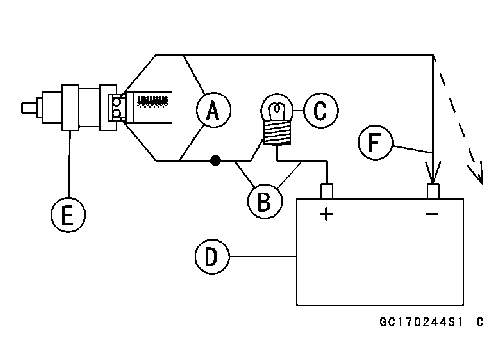
• Use two leads [A] and the same test light set [B] as in “Injector Signal Test”.
Rating of Bulb [C]: 12 V × (3 ~ 3.4) W 12 V Battery [D] • Connect the test light set to the injector [E] as shown. • Open and connect [F] the end of the lead to the battery (–) terminal repeatedly. The injector should click.
• Remove: Fuel Tank (see Fuel Tank Removal) Left Center Fairing (see Center Fairing Removal in the Frame chapter) • Be sure to place a piece of cloth around the fuel hose joint and the delivery pipe. • Insert a minus screw driver [A] into the slit on the joint lock [B]. • Turn the driver to disconnect the joint lock. • Pull the fuel hose joint [C] out of the delivery pipe.
○Connect a commercially available vacuum/pressure pump [A] to the nipple of the delivery pipe [B] with a high-pressure fuel hose [C] (both ends connected with the clamps [D]) as shown. Torque - Fuel Hose Clamp Screws: 1.5 N·m (0.15 kgf·m, 13 in·lb) ○Apply soap and water solution to the areas [E] as shown. ○Watching the pressure gauge, squeeze the pump lever [F], and build up the pressure until the pressure reaches the maximum pressure.
Injector Fuel Line Maximum Pressure Standard: 333 kPa (3.4 kgf/cm², 48 psi)
• Watch the gauge for at least 6 seconds.
○Repeat the leak test, and check the fuel line for no leak- age. • Install the pump outlet hose (see Fuel Tank Installation). • Run the hoses correctly (see Cable, Wire, and Hose Rout- ing section in the Appendix chapter).
1. ECU 2. Fuel Injectors 3. Water-proof Joint C 4. Engine Stop Switch 5. Ignition Switch 6. Ignition Fuse 10 A 7. Fuel Pump Relay (for fuel pump and injectors) 8. Relay Box 9. Main Fuse 30 A 10. Battery 11. Frame Ground 12. Joint Connector
Throttle Grip Free Play Inspection • Refer to the Throttle Control System Inspection in the Pe- riodic Maintenance chapter. Throttle Grip Free Play Adjustment • Refer to the Throttle Control System Inspection in the Pe- riodic Maintenance chapter. Throttle Cable Installation • Install the throttle cables in accordance with Cable, Wire, and Hose Routing section in the Appendix chapter. • Install the lower ends of the throttle cables in the cable bracket on the throttle body assy after installing the upper ends of the throttle cables in the grip.
Throttle Cable Lubrication • Refer to the Chassis Parts Lubrication in the Periodic Maintenance chapter.
Idle Speed Inspection • Refer to the Idle Speed Inspection in the Periodic Main- tenance chapter. Engine Vacuum Synchronization Inspection/Ad- justment • Refer to the Engine Vacuum Synchronization Inspection in the Periodic Maintenance chapter. High Altitude Performance Adjustment • Any modification is not necessary in this model since the inlet air pressure sensor senses inlet air pressure change due to high altitude and the ECU compensates the change.
Throttle Body Assy Removal • Remove: Air Cleaner Housing (see Air Cleaner Housing Removal) Center Fairings (see Center Fairing Removal in the Frame chapter)
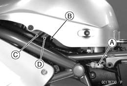
Main Throttle Sensor Connector [A] Fuel Hose Lower End [B] Vacuum Hose [C]
#1, #2 Injector Connector [A] Subthrottle Sensor Connector [B] Subthrottle Sensor Actuator Connector [C] • Loosen: Holder and Duct Clamp Bolts
• Loosen the locknut and screw in the throttle cable adjuster fully to give the cables plenty of play. • Remove the right switch housing and take out the acceler- ator cable upper end [A] and the decelerator cable upper end [B].
• After removing the throttle body assy, stuff pieces of lint
-free, clean cloth into the throttle body holders.
• Install the holder clamp bolts [A] in the direction shown with each bolt heads [B], facing outwards.
• Run the vacuum hose (see Cable, Wire, and Hose Rout- ing section in the Appendix chapter).
• Install the upper ends of the throttle cables in the grip. • Fit the projection [A] of the right switch housing into the hole [B] of the handlebar. • Turn the throttle grip and make sure that the throttle valves move smoothly and return by spring force. • Check the throttle grip free play (see Throttle Control Sys-
tem Inspection in the Periodic Maintenance chapter). • Adjust: Throttle Grip Free Play (see Throttle Control System In- spection in the Periodic Maintenance chapter) Idle Speed (see Idle Speed Adjustment in the Periodic Maintenance chapter)
 Throttle Body Assy Disassembly Throttle Body Assy Disassembly
• Remove the throttle body assy (see Throttle Body Assy Removal).
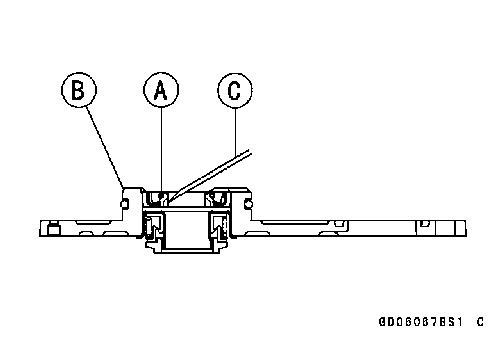
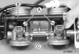
• Remove: Screws [A] Delivery Pipe [B] Fuel Injectors [C]
○Replace the O-rings [A] and seals [B] with the new ones. • Before assembling, blow away dirt or dust from the throttle body and delivery pipe by applying compressed air. • Apply engine oil to the new O-rings of each injector [C], insert them into the delivery pipe and confirm whether the injectors turn smoothly or not. • Install the injectors along with the delivery pipe assy into the throttle bodies.
• Install the throttle body assy (see Throttle Body Assy In- stallation).
Air Cleaner Element Removal/Installation • Refer to the Air Cleaner Element Replacement in the Pe- riodic Maintenance chapter.
• Remove the air cleaner element (see Air Cleaner Element Replacement in the Periodic Maintenance chapter). • Visually check the element [A] for tears or breaks.
ment.
A drain hose is connected to the bottom of the air cleaner to drain water or oil accumulated in the cleaner part. • Remove the left center fairing (see Center Fairing Re- moval in the Frame chapter). • Visually check the drain hose [A] if the water or oil accu- mulates.
 If any water or oil accumulates in the hose, remove the plug [B] from the drain hose and drain it. If any water or oil accumulates in the hose, remove the plug [B] from the drain hose and drain it.
Air Cleaner Housing Removal
Fuel Tank (see Fuel Tank Removal) Hose (Disconnect) [A] Inlet Air Temperature Sensor Connector [B] Screws [C] Cover [D]
• Unscrew the bolts [A] and remove the air cleaner housing [B].
• Install the clamp on the hose [A] so that its pinch heads [B] face the right. • Install the clamp on the breather hose [C] so that its pinch heads [D] face the front.
Fuel Tank Removal
• Wait until the engine cools down. • Open the fuel tank cap [A] to lower the pressure in the tank. ○During tank removal, keep the tank cap open to release pressure in the tank. This makes fuel spillage less.
Seat (see Seat Removal in the Frame chapter) Side Covers (see Side Cover Removal in the Frame chapter) Fuel Tank Bolts [A]
○Use a soft plastic hose [B] as a pump inlet hose in order to insert the hose smoothly. ○Put the hose through the fill opening [C] into the tank and draw the fuel out.
Front [D]
• Disconnect the fuel pump lead connector [A] and the tube [B].
Fuel Return Hose [C] (Red, California Model) Fuel Tank Breather Hose [D] (Blue, California Model)
• Insert a minus screw driver [B] into the slit [C]on the joint lock.
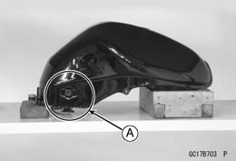
• Remove the fuel tank, and place it on a flat surface. ○Do not apply the load to the fuel pump outlet portion [A] especially the outlet pipe made from resin.
○Besure to plug the evaporative fuel return hose to prevent fuel spilling before fuel tank removal. If liquid or gasoline flows into the breather hose, remove the hose and blow it clean with compressed air.
remains in the fuel tank and fuel pump. Fuel Tank Installation
• Route the hoses correctly (see Cable, Wire, and Hose Routing in the Appendix chapter). • Check that the rubber dampers [A] are on the frame and the fuel tank.
Side Cover [C] Approx. 17 mm (0.67 in.) [D] Front [E] • For California model, note the following. ○To prevent the gasoline from flowing into or out of the canister, hold the separator perpendicular to the ground. ○Connect the hoses according to the diagram of the sys- tem (see Cable, Wire, and Hose Routing section in the Appendix chapter). Make sure they do not get pinched or kinked. ○Route hoses with a minimum of bending so that the air or vapor will not be obstructed.
 • Insert [A] the fuel hose joint [B] straight onto the delivery pipe until the hose joint clicks. • Insert [A] the fuel hose joint [B] straight onto the delivery pipe until the hose joint clicks.
• Push [C] the joint lock [D].
come off.
• Connect the fuel pump and the fuel level sensor connec- tors and the battery (–) cable terminal.
• Visually inspect the gasket [A] on the tank cap for any damage.
• Check to see if the water drain pipe [B] and fuel breather pipe [C] in the tank is not clogged. check the tank cap breather also.
If they are clogged, remove the tank and drain it, and then blow the breather free with compressed air.
Fuel Tank Cleaning • Remove the fuel tank (see Fuel Tank Removal). • Remove the fuel pump inlet hose and the fuel pump (see Fuel Pump Removal). • Pour some high-flash point solvent into the fuel tank and shake the tank to remove dirt and fuel deposits. • Draw the solvent out of the fuel tank. • Dry the tank with compressed air. • Install the fuel pump (see Fuel Pump Installation). • Install the fuel tank (see Fuel Tank Installation).
The Evaporative Emission Control System routes fuel va- pors from the fuel system into the running engine or stores the vapors in a canister when the engine is stopped. Al- though no adjustments are required, a thorough visual in- spection must be made at the intervals specified by the Pe- riodic Maintenance Chart. Parts Removal/Installation
• To prevent the gasoline from flowing into or out of the canister, hold the separator perpendicular to the ground. • Connect the hoses according to the diagram of the sys- tem (see Cable, Wire, and Hose Routing section in the Appendix chapter). Make sure they do not get pinched or kinked. Hose Inspection • Refer to the Evaporative Emission Control System In- spection in the Periodic Maintenance chapter.
• Refer to the Evaporative Emission Control System In- spection in the Periodic Maintenance chapter. Separator [A]
Separator Operation Test
• Connect the hoses to the separator, and install the sepa- rator on the motorcycle. • Disconnect the breather hose from the separator, and in- ject about 20 mL (0.68 US oz.) of gasoline [A] into the separator [B] through the hose fitting. • Disconnect the fuel return hose [C] from the fuel tank [D]. • Run the open end of the return hose into the container and hold it level with the tank top [E]. • Start the engine, and let it idle.
separator works well. If it does not, replace the separator with a new one.
• Refer to the Evaporative Emission Control System In- spection in the Periodic Maintenance chapter. NOTE ○The canister [A] is designed to work well through the motorcycle’s life without any maintenance if it is used under normal conditions.
Cooling System Table of Contents Exploded View........................................................................................................................ 4-2 Coolant Flow Chart................................................................................................................. 4-4 Specifications......................................................................................................................... 4-6 Special Tools.......................................................................................................................... 4-7 Coolant................................................................................................................................... 4-8 Coolant Deterioration Inspection....................................................................................... 4-8 4 Coolant Level Inspection................................................................................................... 4-8 Coolant Draining............................................................................................................... 4-8 Coolant Filling................................................................................................................... 4-8 Pressure Testing............................................................................................................... 4-8 Cooling System Flushing.................................................................................................. 4-9 Coolant Reserve Tank Removal/Installation..................................................................... 4-9 Water Pump............................................................................................................................ 4-10 Water Pump Removal....................................................................................................... 4-10 Water Pump Installation.................................................................................................... 4-10 Mechanical Seal Inspection.............................................................................................. 4-11 Water Pump Housing Disassembly.................................................................................. 4-11 Water Pump Housing Assembly....................................................................................... 4-11 Impeller Assembly............................................................................................................. 4-12 Pump Impeller Inspection................................................................................................. 4-12 Radiator.................................................................................................................................. 4-13 Radiator and Radiator Fan Removal................................................................................ 4-13 Radiator and Radiator Fan Installation............................................................................. 4-14 Radiator Inspection........................................................................................................... 4-14 Radiator Cap Inspection................................................................................................... 4-14 Radiator Filler Neck Inspection......................................................................................... 4-15 Thermostat............................................................................................................................. 4-16 Thermostat Removal......................................................................................................... 4-16 Thermostat Installation...................................................................................................... 4-16 Thermostat Inspection...................................................................................................... 4-16 Hose and Pipes...................................................................................................................... 4-18 Hose Installation............................................................................................................... 4-18 Hose Inspection................................................................................................................ 4-18 Water Temperature Sensor.................................................................................................... 4-19 Water Temperature Sensor Removal/Installation............................................................. 4-19 Water Temperature Sensor Inspection............................................................................. 4-19
8. Reserve Tank 9. Baffle Plate 10. Cylinder Head Cover 11. Thermostat 12. Water Pump Impeller 13. Mechanical Seal G: Apply grease. HG: Apply high-temperature grease. R: Replacement Parts
Permanent type antifreeze is used as a coolant to protect the cooling system from rust and corrosion. When the engine starts, the water pump turns and the coolant circulates. The thermostat is a wax pellet type which opens or closes with coolant temperature changes. The thermostat continuously changes its valve opening to keep the coolant temperature at the proper level. When coolant temperature is below 80.5 ~ 83.5°C (177 ~ 182°F), the thermostat closes so that the coolant flow is restricted through the air bleeder hole, causing the engine to warm up more quickly. When coolant temperature is more than 80.5 ~ 83.5°C, the thermostat opens and the coolant flows. When the coolant temperature goes up beyond 93 ~ 103°C (199 ~ 217°F), the radiator fan relay conducts to operate the radiator fan. The radiator fan draws air through the radiator core when there is not sufficient air flow such as at low speeds. This increases up the cooling action of the radiator. When the temperature is below 91°C (196°F) ~ temperature less than ON temperature, the fan relay opens and the radiator fan stops. In this way, this system controls the engine temperature within narrow limits where the engine op- erates most efficiently even if the engine load varies. The system is pressurized by the radiator cap to suppress boiling and the resultant air bubbles which can cause engine overheating. As the engine warms up, the coolant in the radiator and the water jacket expands. The excess coolant flows through the radiator cap and hose to the reserve tank to be stored there temporarily. Conversely, as the engine cools down, the coolant in the radiator and the water jacket contracts, and the stored coolant flows back to the radiator from the reserve tank. The radiator cap has two valves. One is a pressure valve which holds the pressure in the system when the engine is running. When the pressure exceeds 112.3 ~ 141.7 kPa (1.15 ~ 1.45 kgf/cm², 16.3 ~ 20.5 psi), the pressure valve opens and releases the pressure to the reserve tank. As soon as pressure escapes, the valve closes, and keeps the pressure at 112.3 ~ 141.7 kPa (1.15 ~ 1.45 kgf/cm², 16.3 ~ 20.5 psi). When the engine cools down, another small valve (vacuum valve) in the cap opens. As the coolant cools, the coolant contracts to form a vacuum in the system. The vacuum valve opens and allows the coolant from the reserve tank to enter the radiator.
Oil Seal Driver: 57001-1660
Coolant Deterioration Inspection
• Visually inspect the coolant [A] in the reserve tank.
in the cooling system are corroded. If the coolant is brown, iron or steel parts are rusting. In either case, flush the cooling system.
Coolant Level Inspection • Refer to the Coolant Level in the Periodic Maintenance chapter. Coolant Draining • Refer to the Coolant Change in the Periodic Maintenance chapter. Coolant Filling • Refer to the Coolant Change in the Periodic Maintenance chapter.
• Remove the reserve tank (see Coolant Change in the Pe- riodic Maintenance chapter). • Remove the radiator cap, and install a cooling system pressure tester [A] on the filler neck [B]. NOTE ○Wet the cap sealing surfaces with water or coolant to prevent pressure leaks.
• Build up pressure in the system carefully until the pres- sure reaches 141.7 kPa (1.45 kgf/cm², 20.5 psi). • Watch the gauge for at least 6 seconds.
• Remove the pressure tester, replenish the coolant, and install the radiator cap.
Cooling System Flushing Over a period of time, the cooling system accumulates rust, scale, and lime in the water jacket and radiator. When this accumulation is suspected or observed, flush the cool- ing system. If this accumulation is not removed, it will clog up the water passage and considerable reduce the effi- ciency of the cooling system. • Drain the cooling system (see Coolant Change in the Pe- riodic Maintenance chapter).
• Fill the cooling system with fresh water mixed with a flush- ing compound. • Warm up the engine, and run it at normal operating tem- perature for about ten minutes. • Stop the engine, and drain the cooling system. • Fill the system with fresh water. • Warm up the engine and drain the system. • Repeat the previous two steps once more. • Fill the system with a permanent type coolant and bleed the air from the system (see Coolant Change in the Peri- odic Maintenance chapter). Coolant Reserve Tank Removal/Installation • The coolant reserve tank is removed and installed dur- ing coolant change (see Coolant Change in the Periodic Maintenance chapter).
Water Pump Removal
• Loosen the clamp and remove the radiator hose [A] from the water pump cover [B]. • Remove the water pump cover bolts [C].
• While applying the rear brake, remove the water pump impeller bolt [A]. • Remove: Impeller [B] Water Pump Housing [C]
• When installing the water pump impeller bolt, shift the transmission into 1st gear and apply the rear brake. • Replace the O-rings [A] on the water pump housing with new ones and apply grease them. • Apply high-temperature grease to the lips of the water pump housing oil seal [B].
• Install the water pump housing. • Tighten: Torque - Water Pump Impeller Bolt: 9.8 N·m (1.0 kgf·m, 87 in·lb)
• Install the water pump cover, being careful of the two dowel pins [A]. Torque - Water Pump Cover Bolts: 9.8 N·m (1.0 kgf·m, 87 in·lb)
• Visually inspect the mechanical seal.
cal seal as a unit. ○The sealing seat and rubber seal may be removed easily by hand. Impeller Sealing Seat Surface [A] Rubber Seal [B] Mechanical Seal Diaphragm [C]
 Water Pump Housing Disassembly Water Pump Housing Disassembly
• Take the oil seal [A] out of the housing [B] with a hook [C].
|
|||||||||||||||||||||||||||||||||||||||||||||||||||||||||||||||||||||||||||||||||||||||||||||||||||||||||||||||||||
|
|
Последнее изменение этой страницы: 2016-08-10; просмотров: 344; Нарушение авторского права страницы; Мы поможем в написании вашей работы! infopedia.su Все материалы представленные на сайте исключительно с целью ознакомления читателями и не преследуют коммерческих целей или нарушение авторских прав. Обратная связь - 52.15.35.129 (0.015 с.) |

 Injector Unit Test
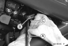 Injector Fuel Line Inspection
 • Check the injector fuel line for leakage as follows.
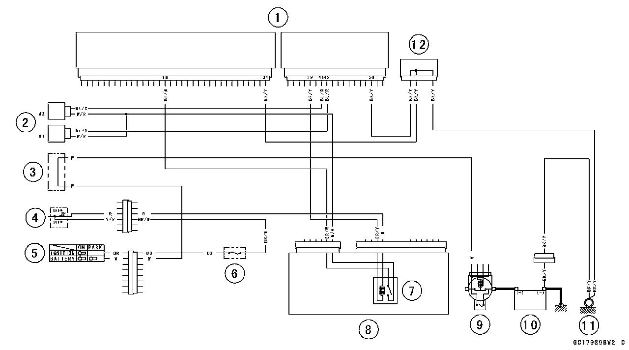


 • Disconnect:
 • Disconnect:
 Throttle Body Assy
 • Remove the throttle cable lower ends [A] from the throttle pulley.
 Throttle Body Assy Installation
 • Install the air cleaner duct clamp screws [A] so that their screw heads [B] face the right.
 • Fit the accelerator cable end [A] and the decelerator cable end [B] into the throttle pulley.
 • Apply a thin coating of grease to the throttle cable upper ends.
 Throttle Body Assy
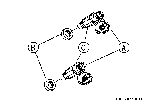 Throttle Body Assy Assembly
 Air Cleaner Element Inspection
 Air Cleaner Oil Draining
 • Remove:
 • Disconnect the breather hose [A] on the upper crankcase.
 Air Cleaner
 Air Cleaner Housing Installation
 • Turn the ignition switch and engine stop switch OFF.
 • Remove:
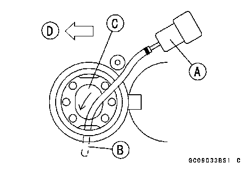 • Draw the fuel out from the fuel tank with a commercially available pump [A].
 • Remove:
 • Be sure to place a piece of cloth [A] around the fuel hose joint.
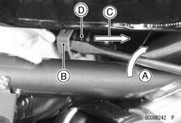 • Turn [A] the driver to disconnect the joint lock [B].
 • Close the fuel tank cap.
 • Note the above WARNING (see Fuel Tank Removal).
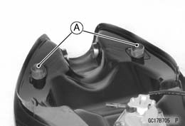 • Check that the dampers [A] are in place on the fuel tank as well.
 • Be sure that the trim seal [A] is on the fuel tank. Reverse Side of Fuel Tank [B]
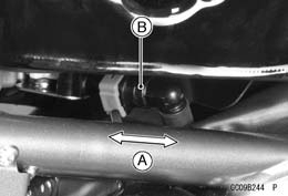 • Push and pull [A] the hose joint [B] back and forth more than two times and make sure it is locked and doesn’t
 Fuel Tank and Cap Inspection

 Separator Inspection
 Evaporative Emission Control System (California Model)
 Canister Inspection


 Bearing Driver Set: 57001-1129
 • Remove the right center fairing (see Center Fairing Re- moval in the Frame chapter).
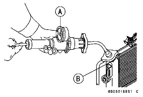 Pressure Testing
 • Drain the coolant (see Coolant Change in the Periodic Maintenance chapter).
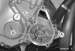 • Shift the transmission into 1st gear.
 Water Pump Installation
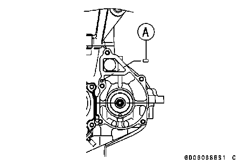 • Be sure that the dowel pin [A] is in position.
 • Replace the O-ring [A] on the water pump cover with a new one and grease it.
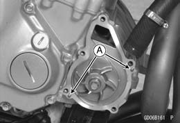 Water Pump
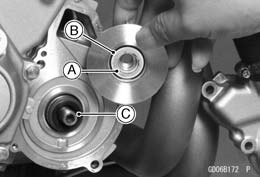 Mechanical Seal Inspection
 • Press the mechanical seal [A] out of the housing with a bearing driver [B].