Заглавная страница Избранные статьи Случайная статья Познавательные статьи Новые добавления Обратная связь FAQ Написать работу КАТЕГОРИИ: ТОП 10 на сайте Приготовление дезинфицирующих растворов различной концентрацииТехника нижней прямой подачи мяча. Франко-прусская война (причины и последствия) Организация работы процедурного кабинета Смысловое и механическое запоминание, их место и роль в усвоении знаний Коммуникативные барьеры и пути их преодоления Обработка изделий медицинского назначения многократного применения Образцы текста публицистического стиля Четыре типа изменения баланса Задачи с ответами для Всероссийской олимпиады по праву 
Мы поможем в написании ваших работ! ЗНАЕТЕ ЛИ ВЫ?
Влияние общества на человека
Приготовление дезинфицирующих растворов различной концентрации Практические работы по географии для 6 класса Организация работы процедурного кабинета Изменения в неживой природе осенью Уборка процедурного кабинета Сольфеджио. Все правила по сольфеджио Балочные системы. Определение реакций опор и моментов защемления |
Table 1-10 typical PATA settings on systems with two PATA host adapters and two drivesСодержание книги
Поиск на нашем сайте
*Use CS with 80-wire PATA cable; use master or single jumpers with 40-wire cable or if CS does not work.
Table 1-11 Typical PATA Settings on Systems with One PATA Host Adapter or When Using Two Drives on a Single Cable
*Use CS with 80-wire PATA cable; use master and slave jumpers with 40-wire cable or if CS does not
work. 28 CompTIA A+ Quick Reference
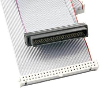
SCSI is actually a small network of devices controlled by an SCSI controller. The controller is a card that plugs into a PCI or PCIe slot and has one of many different kinds of SCSI style ports on the outside and one or two internal ribbon cable connections. One way to spot an SCSI cable is its width. It will always be the widest (most pins) in the PC, markedly more than PATA (40 pins), FDD (34 pins), and SATA (7 pins). (SATA sometimes has 15 pins if it provides its own power.) Although some implementations of SCSI used a 25-pin cable, most narrow (8-bit bus) SCSI use a 50-pin cable. All wide (16-bit bus) SCSI use a 68-pin cable. External SCSI devices have two con-nectors to allow the device to pass through SCSI signals intended for another device. Figure 1-14 compares HD and LD narrow SCSI cables used for internal devices.
Figure 1-14 HD (top) and LD (bottom) 50-pin narrow SCSI cables.
An SCSI array requires unique IDs, created using a binary code: 3 bits for SCSI, and 4 bits for wide SCSI. This code is set by jumper, dip switch, push button switch, or can be configured with a separate SCSI BIOS. Just like on a network, every device needs a unique ID number from 0 to 15. SCSI arrays also need a common medium (SCSI cable), termination at each, and a controller card.
SCSI “daisy-chains” the necessary terminators at each end to absorb the signal. In place of ter-minators, it is common in narrow SCSI implementations to install a termination-enabled device at each end to serve as both HDD and terminator. However, wide and higher-speed SCSI imple-mentations use active (powered) terminators that plug into the unused SCSI post on the end of the daisy chain.
RAID
Redundant array of inexpensive (or independent) disks (RAID) has several defined levels, but the most common are 0, 1, and 5. RAID 0 writes the data across two drives using a technique called Chapter 1: Hardware 29
striping. This increases speed, but does not provide any data protection. RAID 1 (mirroring), using two disks, simply copies changes from one HDD to the other in real time. Desktop computers with onboard RAID adapters (typically SATA in newer systems, PATA in older systems) support RAID 0, RAID 1, and some also support RAID 1+0 (RAID 10).
Combinations of RAID standards such as RAID 1+0 (also known as RAID 10) and 0+1 are also popular, and they require at least four disks, because they are either two striped disks that are mir-rors to two others, 0+1, or they are two mirrored disks striped to two others, 1+0 (10). In RAID 5, there are at least three HDDs. RAID 5 writes data across the drives and also stores information about the contents of each drive on the others. In the event of a drive failure, the data stored on the failed drive can be re-created from the information stored on the other drives. RAID 5 is com-monly used on servers, and typically uses SCSI, SATA, or SAS (Serial Attached SCSI, a version of SCSI based on SATA).
Media Cards
The various flash memory storage cards available are used primarily in phones, cameras, and other portable devices. PCs use card readers to interface with this type of storage media. The secure digital card (SD card) is the most common media card. One particular note about SD cards is they have a switch that makes the card read/write or read-only. Floppy disks also have this feature. SD cards are small and hold a considerable amount of data that is comparable to small HDDs. The secure digital high-capacity (SDHC) card has the same physical form factor as SD card, but uses a different internal design to support higher capacities. All devices that can use SDHC cards can also use SD cards, but not vice versa. Figure 1-15 compares different types of flash memory storage to a small CD-R and floppy disk (right) and a U.S. penny (lower left).
Figure 1-15 Media used in digital cameras. At bottom-left center is an SD card, the most commontype of flash memory card. 30 CompTIA A+ Quick Reference
Other Storage Devices
Floppy disk drives (FDD) are installed in a 3.5-inch drive bay (or a 5.25-inch drive bay by using an adapter). FDDs use 3.5-inch flexible magnetic media in a rigid plastic shell (refer to Figure 1-15). A spring-loaded slider protects the media when it is removed from the drive. The capacity of standard FDD media is 1.44MB.
USB flash drives connect through a USB port. These are easily lost and should not be used to store secure information unless the drive is equipped with encryption hardware or has been encrypted with Windows BitLocker To Go or a third-party encryption program.
Network-attached storage (NAS) is an HDD with a network interface card (NIC) interface. These devices often use a web-based management program. These devices are a small office, home office (SOHO) version of proper file servers found in corporate environments. A mapped drive is a short-cut for a network share or a NAS device.
Cooling
There are several methods of removing heat from a PC. As noted previously, an active heat sink is commonly used to draw hot air away from a CPU. Many GPUs (graphics processors) also have their own cooling fan and heat sink assembly.
A thermal compound is used between the heat sink and the CPU. Note that the thermal compound is poisonous and toxic to humans. Use care when applying or removing thermal compound. Dust collects on the heat sink’s fins and the fan, which decreases its efficiency. Use compressed air or a PC vacuum to remove dust.
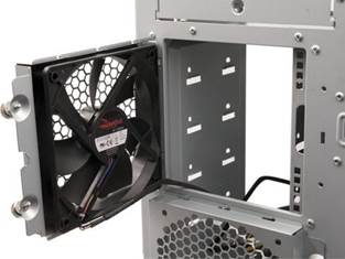
Although almost all power supplies contain fans, most desktop computers feature one or more fans to draw air through the system. Typical fan sizes range from 80mm to 140mm. Figure 1-16 shows a typical 120mm fan installed in a computer to cool internal hard disk drives.
Figure 1-16 A 120mm cooling fan after installation. Chapter 1: Hardware 31
Power Supplies
Safety first: Do not open a power supply. It contains capacitors that hold a dangerous charge, even while unplugged. It is a field replaceable unit (FRU). In other words, if it is broken, simply replace the entire power supply.
Power supplies are measured in watts. The watts output should exceed the PC’s power demand. There are four kinds of power connections from the power supply to the PC. Berg and Molex are the standard small and large (respectively) 4-pin connections for drives and other devices. The motherboard uses a 20-pin or 24-pin connector, and most have an additional 4-pin (ATX12V) or 8-pin (EPS12V) connector used for providing extra power for CPUs. 15-pin power connectors are used with SATA hard disks. Power supplies designed for use with SLI or CrossFire (dual GPU) systems also include 6-pin or 8-pin (6+2) PCIe power connectors. Figure 1-17 illustrates typical power connectors found on most recent power supplies.
1. PCIe (6-pin)
2. SATA
3. ATX 24-pin
4. Molex
5. Berg
6. EPS12V (both
4-pin connectors)
7. ATX12X (one
4-pin connector)
8. PCIe (6+2 pin)
Figure 1-17 Power supply connectors used in typical systems.
When replacing a power supply, verify that the new power supply has the same form factor and the same types and amounts (or more) of motherboard and drive connectors as the old one. Also, the new power supply should have the same or (preferably) higher rating in watts and amperage for 12V circuits on the motherboard and connected devices as the old one. Power supplies for many Dell models use proprietary wiring schemes and cannot be interchanged with standard power sup-plies, or vice versa.
Standard power supply wire colors include:
Orange—+3.3V Red—+5V
Yellow—+12V Black—Ground
Gray—Power Good Purple—+5V standby 32 CompTIA A+ Quick Reference
White—-5V or no connection Green—PS-on
Blue—-12V
Power supplies built for international use run at 115/230 volts, and might use a selector switch or automatically detect correct voltage.
Power fluctuations are devastating to a PC. Table 1-12 describes five power fluctuations.
|
|||||||||||||||||||||||||||||||||||||||||||||||||||||||||||||||||||||||||||||||||||||||||||||||||||||||||||||
|
|
Последнее изменение этой страницы: 2017-02-08; просмотров: 363; Нарушение авторского права страницы; Мы поможем в написании вашей работы! infopedia.su Все материалы представленные на сайте исключительно с целью ознакомления читателями и не преследуют коммерческих целей или нарушение авторских прав. Обратная связь - 18.188.211.58 (0.006 с.) |