Заглавная страница Избранные статьи Случайная статья Познавательные статьи Новые добавления Обратная связь FAQ Написать работу КАТЕГОРИИ: ТОП 10 на сайте Приготовление дезинфицирующих растворов различной концентрацииТехника нижней прямой подачи мяча. Франко-прусская война (причины и последствия) Организация работы процедурного кабинета Смысловое и механическое запоминание, их место и роль в усвоении знаний Коммуникативные барьеры и пути их преодоления Обработка изделий медицинского назначения многократного применения Образцы текста публицистического стиля Четыре типа изменения баланса Задачи с ответами для Всероссийской олимпиады по праву 
Мы поможем в написании ваших работ! ЗНАЕТЕ ЛИ ВЫ?
Влияние общества на человека
Приготовление дезинфицирующих растворов различной концентрации Практические работы по географии для 6 класса Организация работы процедурного кабинета Изменения в неживой природе осенью Уборка процедурного кабинета Сольфеджио. Все правила по сольфеджио Балочные системы. Определение реакций опор и моментов защемления |
Dual-Channel and Triple-Channel MemoryСодержание книги
Поиск на нашем сайте
x86 (32-bit) and x86-64 (64-bit) processors have a 64-bit data bus, the same size data bus as on DIMMs. Therefore, memory can be added one module at a time. 10 CompTIA A+ Quick Reference
However, to improve performance, many recent systems support dual-channel or triple-channel memory. In these systems, you can add two or three matched memory modules (modules with the same speed and timing characteristics, and for most motherboards, they should also be the same size in GB), and the system will access them as a single very wide module for increased speed. To determine if a particular system or motherboard supports these memory access methods, check the documentation. If you don’t use matched modules or if the modules are not installed in the correct sockets, the memory will be accessed as separate 64-bit modules, providing lower memory perfor-mance than with dual-channel or triple-channel access.
Other Types of RAM
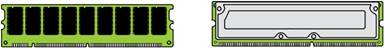
The RAMBUS Inline Memory Module (RIMM) uses a proprietary 184- or 232-pin slot. This RAM, often called RDRAM, is found in some game console systems and a limited number of PCs. On such systems, empty RIMM slots must be filled with Continuity RIMM (CRIMM) modules.
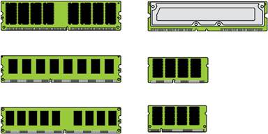
Laptops use a small form factor called Small Outline DIMM (SODIMM). Many netbooks, Ultra Mobile PCs (UMPC), and portable devices, such as cell phones and PDAs, use a MicroDIMM form factor. Figure 1-5 compares the relative size and form factors found in RAM.
Figure 1-5 Memory module comparison. Chapter 1: Hardware 11
VRAM and Virtual RAM
VRAM is video RAM for the use of the graphic processing unit (GPU). Most GPUs now use vari-ations on SDRAM. VRAM does not stand for virtual RAM. Virtual RAM (more often referred to as a virtual memory, paging file, or swap file) is space on the hard disk drive (HDD) that the RAM uses as an overflow area.
Parity and ECC
Parity is a method of verifying data integrity. It is used when the reliability of the data is more important than the speed at which it is written or read. Parity adds a bit to each byte so that every byte is an even number. When the data is read or received, the bytes should still be even. If not, the data is corrupt. Parity is used in some network communications, hard drives, and RAM, primarily in servers and workstations. Error correction code (ECC) detects and fixes corrupt data in RAM. Both parity and ECC decrease memory performance, but increase reliability.
BIOS
The options selected for the BIOS are stored on the complementary metal-oxide semiconductor (CMOS) chip that is on the motherboard. The BIOS handles fundamental system configuration. The CMOS chip is actually a combination of NVRAM (nonvolatile RAM, which can retain its contents without power) and volatile RAM. The BIOS chip also contains NVRAM, which allows the BIOS to be updated (flashed). If the BIOS cannot recognize a new device, updating the BIOS is a solution. A small battery maintains a charge so that the settings are not lost in the RAM when the PC is off. If the date and time reset when the computer restarts, replace the battery. The BIOS allows you to do the following:
Enable/disable integrated devices Order the boot sequence
Manage drive controllers
View PC diagnostic information such as CPU and motherboard temperatures and onboard fan speeds
Configure CPU and memory speeds and timing Adjust power management settings
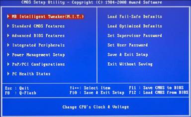
The BIOS feature that provides for these settings to be changed is often referred to as the CMOS setup program, because the CMOS stores the values that you select. Figure 1-6 illustrates a typical CMOS setup program’s main menu. 12 CompTIA A+ Quick Reference
Figure 1-6 This Award CMOS setup program offers a wide range of adjustments in its menus.
Table 1-4 provides a detailed discussion of the most important CMOS/BIOS settings. Use this table as a quick reference to the settings you need to make or verify in any system. Examples of these and other settings are provided in the following sections.
|
||||||||||||
|
|
Последнее изменение этой страницы: 2017-02-08; просмотров: 440; Нарушение авторского права страницы; Мы поможем в написании вашей работы! infopedia.su Все материалы представленные на сайте исключительно с целью ознакомления читателями и не преследуют коммерческих целей или нарушение авторских прав. Обратная связь - 216.73.216.102 (0.007 с.) |