Заглавная страница Избранные статьи Случайная статья Познавательные статьи Новые добавления Обратная связь FAQ Написать работу КАТЕГОРИИ: ТОП 10 на сайте Приготовление дезинфицирующих растворов различной концентрацииТехника нижней прямой подачи мяча. Франко-прусская война (причины и последствия) Организация работы процедурного кабинета Смысловое и механическое запоминание, их место и роль в усвоении знаний Коммуникативные барьеры и пути их преодоления Обработка изделий медицинского назначения многократного применения Образцы текста публицистического стиля Четыре типа изменения баланса Задачи с ответами для Всероссийской олимпиады по праву 
Мы поможем в написании ваших работ! ЗНАЕТЕ ЛИ ВЫ?
Влияние общества на человека
Приготовление дезинфицирующих растворов различной концентрации Практические работы по географии для 6 класса Организация работы процедурного кабинета Изменения в неживой природе осенью Уборка процедурного кабинета Сольфеджио. Все правила по сольфеджио Балочные системы. Определение реакций опор и моментов защемления |
Working principle of oil injectorСодержание книги
Поиск на нашем сайте
Inside the injector surrounding the iron core there is an electromagnetic coil which leads to the two electrodes, namely, the injector input control interface. When the electromagnetic coil is energized, the generated electromagnetic force makes the ball valve rise by overcoming the spring force of the ball valve and fuel pressure, so the high-pressure fuel (250Kpa) inside the fuel pipe can pass through the injector valve seat hole, flowing through the spray orifice board and forming a conical mist sprayed into the intake valve. When the injector is in outage, electromagnetic coil's electromagnetic force disappears, and the ball valve of the injector closes automatically under the action of return spring to make fuel injection action of the injector stop. 16.2.2.2 Appearance of oil injector:
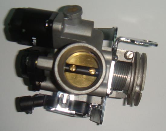
16.2.2.2 Note for use of injector: 1. Inside the injector there is a filter, but it is not a serviceable part, because it is only designed to filter out the accumulated impurities between the fuel filter and injector of the oil line. The impurities can cause injection bonding, flow offset and leakage and other faults, so the fuel filter is very important. 2. Only the injector of the same parts number can be replaced, Throttle body 16.2.3.1 Working principle of throttle body: Throttle body is mainly made up of principle cast body, return spring, throttle cable, throttle body position sensor and idle speed adjustment screw, and throttle body position sensor is to provide throttle opening to the ECU; idle adjustment screw to control the idle speed and stability. Clockwise reduces the bypass gas, and reduces the idle speed while counterclockwise increases the bypass gas, and increases the idle speed; in general it requires about two laps. 16.2.3.2 Appearance of throttle body:
Clearing of throttle body Use throttle cleaner to clean the throttle body; spray the cleaner on the internal wall of the throttle body and brush gently off the dust, coke, etc.; make sure no dirt clogging the side-channel. Cylinder head temperature sensor 16.2.4.1 Working principle of cylinder head temperature sensor: The engine cylinder head temperature sensor is used for air-cooled engine to measure the engine cylinder head temperature; within the temperature range of the sensor, its resistance varies with engine temperature, and its temperature characteristic is the negative temperature coefficient resistance characteristics. It is a part which is not maintainable. 16.2.4.1 Appearance of cylinder temperature sensor:
Intake air temperature sensor 16.2.5.1 Working principle of intake air temperature sensor: It is used to measure the temperature of incoming air, and its resistance will vary with the temperature of the intake air; its characteristic is also negative temperature coefficient resistance characteristics. It is also a part which cannot be repaired. 16.2.5.2 Appearance of intake air temperature sensor:
Intake air pressure sensor 16.2.6.1 Working principle of intake air pressure sensor: The sensor is used to measure the absolute pressure of intake air elbow to reflect different inlet pressure according to the resistance value, and the inlet pressure can be thus indirectly converted into calculation of the size of the intake air into the engine combustion chamber. It is not the repairable parts 16.2.6.1 Appearance of intake air pressure sensor:
Oxygen sensor 16.2.7.1 Working principle of oxygen sensor: The sensor can be used to detect the amount of oxygen in the exhaust gas in the engine exhaust pipe for the ECU internal fuel closed-loop control, so that the combustion of engine has always been maintained at the most reasonable proportion of air and petrol. 16.2.7.2 Appearance of oxygen sensor:
Ignition coil 16.2.8.1 Working principle of ignition coil: Ignition coil can provide energy to the spark plug, and it is the high-voltage that connects the ignition coil and spark plug.
16.2.8.2 Appearance of ignition coil:
Idling stepper engine 16.2.9.1 Working principle of idling stepper engine: Function of idling control valve is to control the circulation area of the airway next to the throttle body to regulate the amount of air entering the engine to achieve the engine idling control. 16.2.9.1 Appearance of idling stepper engine:
Fuel pump 16.2.10.1 Working principle of fuel pump: The electric oil pumps and pressure regulator works together to provide 250Kp gas pressure to the engine, installed at the bottom of the fuel tank. 16.2.10.2 Appearance of fuel pump:
16.2.10.3 Fuel pumps fault diagnosis: 1. After the key is turned on, the pump will operate for about 3 seconds or so; if you can hear the pump running, please go directly to 4: 2. Disconnect the pump connector, detect whether the supply voltage of the pump is about 12V; 3. If there is no problem for step 2, make external connection to battery to provide 12V DC to test whether the pump is operating well. 4. If the pump is operating normally, use petrol pressure gauge to test the tubing pressure of the front-end of engine is about 250Kpa during idling of engine; 5. If the line pressure is lower than 220Kpa, check if there is leakage for the oil pipeline, if oil pump is inverted, or if there is blockage for filter. 16.2.10.4 Common problems for fuel pump: 1. The fuel pump assembly plug is reversed, resulting in the reversal of the fuel pump, so it cannot provide sufficient fuel pressure to the engine, causing the engine does not work. 2. Pump cannot rotate because of damage. 16.2.10.5 Notes for use of fuel pump: 1. There is no petrol in the fuel tank for the new enginecycle at the beginning, and there is much air in the fuel oil pipeline after the petrol is filled, so it needs to move the engine for a lot to let the air out completely and the engine can work properly; this is normal; being unable to start for a long time will not appear in the following start-up. 2. Because petrol can cool the fuel pump, do not let the pump work with little oil or no oil; otherwise it will burn the fuel pump. Troubleshooting diagnosis Fault light is located on the dashboard with a FI mark below. Under normal circumstances, open the key, the fault light will be on, which means that the EFI system is in power state and can work; the fault light are not on, which said EFI circuit is out of power supply, and will not work, and it needs to check the fuse and the battery positive and negative connections. After the engine is started, the fault light is off, which means there is no fault; conversely, if the engine is started the fault light is still on for long, which said the EFI system is not working properly, and there is a failure needing to troubleshoot. At present there are three ways to detect fault:
|
||||||||||||||
|
|
Последнее изменение этой страницы: 2016-04-08; просмотров: 409; Нарушение авторского права страницы; Мы поможем в написании вашей работы! infopedia.su Все материалы представленные на сайте исключительно с целью ознакомления читателями и не преследуют коммерческих целей или нарушение авторских прав. Обратная связь - 18.117.232.108 (0.009 с.) |