Заглавная страница Избранные статьи Случайная статья Познавательные статьи Новые добавления Обратная связь FAQ Написать работу КАТЕГОРИИ: ТОП 10 на сайте Приготовление дезинфицирующих растворов различной концентрацииТехника нижней прямой подачи мяча. Франко-прусская война (причины и последствия) Организация работы процедурного кабинета Смысловое и механическое запоминание, их место и роль в усвоении знаний Коммуникативные барьеры и пути их преодоления Обработка изделий медицинского назначения многократного применения Образцы текста публицистического стиля Четыре типа изменения баланса Задачи с ответами для Всероссийской олимпиады по праву 
Мы поможем в написании ваших работ! ЗНАЕТЕ ЛИ ВЫ?
Влияние общества на человека
Приготовление дезинфицирующих растворов различной концентрации Практические работы по географии для 6 класса Организация работы процедурного кабинета Изменения в неживой природе осенью Уборка процедурного кабинета Сольфеджио. Все правила по сольфеджио Балочные системы. Определение реакций опор и моментов защемления |
Over-high temperature of cylinder bodyСодержание книги
Поиск на нашем сайте
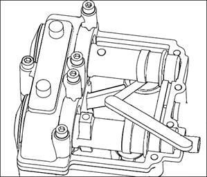
Water pump impeller damaged Radiator fan broken Lack of cooling liquid Temperature sensor damaged Water pump Disassemble Loosen the fastening bolt, remove the crankcase right cover and remove the gasket.
Remove the water pump gear, loosen the
Inspection Check whether the parts wear. If badly worn, replace it. Note: No damage should be made to the gasket and the box joints in operation. Installation Installation should be made in accordance with the reverse order of the removal. Water pump disassembling
1 Hexagon socket cylinder bolt 2 Gasket 6 3 Water pump cover 4 Water cover seal gasket 5 Pin 6 Impeller 7 Water seal assembly 8 Water pump shaft 9 Pin3*22 10 Water pump gear 11 Gasket Cylinder head
XI Cylinder Head Preparatory data 11.1 Fault diagnosis 11.2 Cylinder Head/Valve 11.3 Preparatory Data Function of cylinder head: Cylinder head is used to seal cylinder and form a combustion chamber with piston to hold high-temperature and high-pressure fuel gas. It accomplishes air intake and exhausting operation with valve mechanism. Precautions on Operation To ensure sealing between cylinder head and cylinder body, there is a great bolt pretension on the cylinder head. Pre-tightening force value 12 NЎ¤m; Locking force value: 30 NЎ¤m. All the components shall be cleaned before inspection and test, and purged with high-pressure air. Table of standard values of baseline projects and allowable limit Unit: mm
Fault Diagnosis Low compression pressure Noisy cylinder head Improperly adjusted valve clearance Improperly-adjusted valve clearance Valve burnt or bent Valve spring hurt Poorly sealed valve race Over-high compression pressure Air leakage at cylinder head Too much carbon deposited in the combustion chamber Improperly installed spark plug
Cylinder Head Removal
Cam shaft measurement
Measure the size of the cam matching journal Admission can shaft: Allowable limit: ¦µ24.957 mm
Allowable limit: ¦µ24.957 mm Measure the height of the cam shaft Allowable limit: Intake 36.9 mm Exhaust 35.9 mm
Remove the tappet; compress the valve spring with valve spring compressor; remove the valve lock clamp. Remove the gas distribution adjustment gasket, valve spring, the upper and lower seat of valve spring, valve.

Inspection
If flatness of junction surface of cylinder cover exceeds the service limit, put a piece of fine sandpaper on the flat plate and fit the sandpaper with junction surface of cylinder cover; and then push the sandpaper to grind in figure of Ў°8Ў± way.
Measure the free length of the valve spring.
Measure the outer diameter of the valve stem. Allowable limit: Intake §¶4.455 mm Exhaust §¶4.448 mm
Check valve guide. Please eliminate the carbon deposition in the valve guide with a reamer before inspection.
Clearance between valve and valve guide Allowable limit: Intake Valve: 0.08m. Exhaust valve: 0.1mm. Valve Guide Replacement Attention: Put the valve guide into the freezing chamber of refrigerator for one hour to freeze it.
Fix the cylinder head and remove the valve guide from upper side of cylinder head with a special valve guide remover.
Install a new O ring onto the new valve guide. Install the valve guide from the top of cylinder head. Attention: Please do not hurt cylinder head while installing valve guide.
When the valve guide is inserted, fix and adjust it with a valve guide reamer.
Rotate the reamer in clockwise direction.
Remove carbon deposited in combustion chamber and valve and clean thoroughly intake and exhaust valves. Inspect width of contact surface of valve seat (width of valve race) Allowable limit: intake/exhaust: 1.6mm.
Remove hackly and ragged parts on the valve race with a 45Ўг angled milling cutter. Note: Apply a layer of transparent or Prussian blue film onto the valve race so that it can be observed clearly.
Remove the milling cutter and check the places processed.
Standard valve race width: Intake: 0.9mm Exhaust: 1.0mm
If contacted place is the higher part of valve, please use a 32Ўг angle plain milling cutter to lower the valve race.
Grind and cut valve race with a 45Ўг angle precise milling cutter till it meets the required specification. After completion of valve race grinding and cutting, please apply some polishing agent on the surface of valve. Polish the valve gently.
Installation Install the cylinder head in the reverse order of removal.
Attention: While installing valve spring, the end with short spring links heads combustion chamber. While installing valve collet, please compress valve spring with a valve spring compressor and install the valve collet. While installing valve, please apply appropriate amount of engine oil on the surface of valve stem, and then install it into valve guide.
Valve clearance adjustment With a special cylinder head cover for valve clearance adjustment installed, measure the clearance between the cam base circle and tappet with the testing gauge. Inlet valve: 0.15-0.2mm Exhaust valve: 0.2-0.25mm
Cylinder Block and Piston
|
|||||||||||||||||||||||||||||||||||||||||||||||||||||||||||||||||||||||||||||||||||||||||||||||||||||||||||||||||||||||||||||||||||
|
|
Последнее изменение этой страницы: 2016-04-08; просмотров: 379; Нарушение авторского права страницы; Мы поможем в написании вашей работы! infopedia.su Все материалы представленные на сайте исключительно с целью ознакомления читателями и не преследуют коммерческих целей или нарушение авторских прав. Обратная связь - 3.145.32.238 (0.008 с.) |


 Remove the impeller, the water pump shaft,

 Loosen the fastening bolt, and
  Remove the tensioner, loosen the chain
  Exhaust cam shaft:
 Remove the bolt, nut and the cylinder head cover
 Valve disassembling


 Measure flatness of junction surface of cylinder cover
 Allowable limit: 0.05mm.


 Attention: Rotate the reamer in clockwise. Please do not rotate the reamer in counterclockwise.
 Measure valve guide ID.
 Allowable limit: Intake/Exhaust: §¶4.53mm.
 When the clearance between valve and valve guide exceeds service limit value, please replace the valve guide. When a valve guide is replaced, surface of valve seat retainer shall be fixed and adjusted.
 Heat with electric furnace or oven the cylinder head to 100-150Ўж.
 Attention: When a reamer is used to cut, please apply some amount of cutting lubricant onto it.
 Valve Race Fixing and Adjustment
 Remove 1/4 of external edge of valve race with a 30Ўг angle milling cutter.
 Remove 1/4 of bottom of valve race with a 70Ўг angle milling cutter.
 Grind and cut valve race with a 45Ўг angle precise milling cutter till it gains a proper width.
 If contacted place is the lower part of valve, please use a 60Ўг angle internal milling cutter to raise the valve race.