Заглавная страница Избранные статьи Случайная статья Познавательные статьи Новые добавления Обратная связь КАТЕГОРИИ: ТОП 10 на сайте Приготовление дезинфицирующих растворов различной концентрацииТехника нижней прямой подачи мяча. Франко-прусская война (причины и последствия) Организация работы процедурного кабинета Смысловое и механическое запоминание, их место и роль в усвоении знаний Коммуникативные барьеры и пути их преодоления Обработка изделий медицинского назначения многократного применения Образцы текста публицистического стиля Четыре типа изменения баланса Задачи с ответами для Всероссийской олимпиады по праву 
Мы поможем в написании ваших работ! ЗНАЕТЕ ЛИ ВЫ?
Влияние общества на человека
Приготовление дезинфицирующих растворов различной концентрации Практические работы по географии для 6 класса Организация работы процедурного кабинета Изменения в неживой природе осенью Уборка процедурного кабинета Сольфеджио. Все правила по сольфеджио Балочные системы. Определение реакций опор и моментов защемления |
Two-wheel Motorcycle QJ125GY-16AСтр 1 из 19Следующая ⇒
Two-wheel Motorcycle QJ125GY-16A Instruction and Maintenance Manual
ZHEJIANG QIANJIANG MOTORCYCLE CO., LTD. Contents PrefaceЎ¤ - 1 - Preparatory DataЎ¤ - 2 - Inspection/Adjustment - 15 - Check and Maintenance of Body Ў¤ - 32 - I Braking System Ў¤Ў¤ - 34 - 1.1 Maintenance InstructionЎ¤ - 34 - 1.2 Fault diagnosis - 35 - 1.3 Front Hydraulic BrakeЎ¤ - 36 - 1.4 Back liquid brakeЎ¤ - 38 - II Vehicle Housing Ў¤ - 42 - III Front Wheel/Front Suspension Ў¤ - 45 - 3.1 Preparatory DataЎ¤ - 45 - 3.2 Fault diagnosis - 45 - 3.3 Front wheel - 47 - 3.4 Direction handleЎ¤ - 49 - 3.5 Front forkЎ¤ - 49 - IV Rear Wheel/Rear Suspension Ў¤ - 54 - 4.1 Preparatory DataЎ¤ - 54 - 4.2 Fault Diagnosis - 55 - 4.3 Rear wheel - 56 - 4.4 Rear Shock Absorber - 57 - 4.5 Rear Swing ArmЎ¤Ў¤ - 58 - 4.6 Drive ChainЎ¤ - 59 - V Storage Battery/Charging System Ў¤Ў¤ - 62 - 5.1 Preparatory DataЎ¤ - 62 - 5.2 Fault Diagnosis - 63 - 5.3 Storage BatteryЎ¤ - 64 - 5.4 Charging SystemЎ¤Ў¤ - 65 - 5.5 Voltage-current Regulator - 66 - 5.6 Alternator Charging Coil - 67 - 5.7 alternator light coil - 67 - 5.8 disassembly of alternator - 68 - VI Ignition System Ў¤Ў¤ - 71 - 6.1 Preparatory DataЎ¤ - 71 - 6.2 Fault Diagnosis - 72 - 6.3 Ignition System InspectionЎ¤ - 73 - 6.4 CDI AssemblyЎ¤ - 75 - 6.5 Ignition Coil - 75 - 6.6 Trigger - 76 - VIIStarting System Ў¤Ў¤ - 78 - 7.1 Preparatory DataЎ¤ - 78 - 7.2 Fault Diagnosis - 79 - 7.3 Starting Motor - 79 - 7.4 Starting RelayЎ¤ - 81 - VIIIBulbs/Switches/Instruments - 82 - 8.1 Preparatory DataЎ¤ - 82 - 8.2 Fault Diagnosis - 82 - 8.3 Headlamp Bulb Replacement - 83 - 8.4 Front Turn Signal Lamp Bulb Replacement - 84 - 8.5 Taillight/license plate lamp/rear turn-lamp bulb replacement - 84 - 8.6 Instrument - 85 - 8.7 Main SwitchЎ¤ - 85 - 8.8 HornЎ¤ - 86 - 8.9 Handle switchЎ¤ - 86 - Engine Inspection and Maintenance Ў¤ - 87 - IX Lubricating System Ў¤Ў¤ - 89 - 9.1 Preparatory DataЎ¤ - 89 - 9.2 Fault Diagnosis - 89 - 9.3 Oil PumpЎ¤ - 90 - X Cooling system Ў¤Ў¤ - 93 - 10.1 Preparatory dataЎ¤ - 93 - 10.2 Fault diagnosis - 93 - 10.3 Water pumpЎ¤ - 94 - XI Cylinder Head Ў¤ - 97 - 11.1 Preparatory DataЎ¤ - 97 - 11.2 Fault Diagnosis - 98 - 11.3 Cylinder HeadЎ¤ - 98 - XII Cylinder Block and Piston Ў¤ - 107 - 12.1 Preparatory DataЎ¤ - 107 - 12.2 Fault Diagnosis - 108 - 12.3 Cylinder HeadЎ¤ - 108 - XIII Crankcase Ў¤ - 113 - 13.1 Preparatory DataЎ¤ - 113 - 13.2 Fault Diagnosis - 114 - 13.3 CrankcaseЎ¤ - 115 - 13.4 ClutchЎ¤ - 116 - 13.5 Gearshift mechanismЎ¤Ў¤ - 121 - 13.6 Crankcase connecting rod combinationЎ¤ - 122 - 13.7 Variable speed chamber - 125 - Exhaust System Inspection and Maintenance Ў¤ - 128 - XV Emission Control System Ў¤Ў¤ - 129 - 15.1 Emission Control System GuaranteeЎ¤ - 129 - 15.2 Regular maintenance guidelines - 129 - 15.3 Emission Control System Mechanical Functions - 130 - 15.4 Catalyst conversion systemЎ¤Ў¤ - 131 - 15.5 Solutions to Idle Exhaust Exceeding Specified ValueЎ¤ - 132 - Inspection and Maintenance of EFI System Ў¤Ў¤ - 133 - XVIEFI System Description Ў¤ - 134 - 16.1 Introduction to EFI System of finished enginecycleЎ¤ - 134 - 16.2 EFI system parts - 134 - 16.3 Troubleshooting diagnosis - 146 - 16.4 Common troubleshootingЎ¤ - 153 - 16.4.3 Concise troubleshootingЎ¤ - 154 - QJ125GY-16A circuit diagram Ў¤Ў¤ i
Preface
The Instruction and Maintenance Manual contains an introductory description of maintenance on QJ125GY-16A motorcycle. Preparatory data include attentions that shall be paid on all the maintenance operations in the Instruction and Maintenance Manual. Please read the manual carefully before operation. Check and adjustment contains main aspects for inspection and adjustment, safety of the vehicle, performance and maintenance of each component. This shall be started from the time of periodical inspection.
The parts following Chapter One demonstrate the main point of disassembly, installation and check of electrics parts, finished vehicle, engine and other components. System diagrams, breakdown drawings, fault diagnosis, maintenance and other explanatory contents are presented before each part. Note: The parts which are not explained separately in the manual apply to both of the motorcycles. For any pattern and structure change of the motorcycle, or any difference between the product and pictures, drawings and instructions in the manual, the product shall prevail. The product is subject to changes without prior personal notice.
ZHEJIANG QIANJIANG MOTORCYCLE CO., LTD. Finished Automobile Institute Preparatory Data General Safety Maintenance Rules Specification Table Fault Diagnosis General Safety Carbon monoxide (CO) When it is necessary to start the engine, please make sure the operation area is well ventilated. Never run the engine in an enclosed place. Attention
It is necessary to run the engine in an open area. To run the engine in an enclosed site, ventilation system shall be used. Gasoline Operate in well-ventilated site. No fire or smoking is allowed in operation site and gasoline storage place. Storage Battery Electrolyte in the storage battery has sulfuric acid, so leave eyesЎўskin and clothes away from it. Once got electrolyte on our skin or clothes, you will have to wash them by fresh water thoroughly; once into our eyes, to see a doctor immediately is necessary. Special Tool When disassembly and installation is in process, general tools and special tools should be selected correctly. When it is time to use the special, the general can not be substitution. Besides, appropriate power is welcomed to avoid the damage of components. High Temperature Burn Tips: Do not be burned by engine, exhaust pipe,silencer and other components with high temperature. When operating together with others, youЎЇd better look after each other and keep a way for safety. Maintenance Rules While repairing and servicing, use tools of metric system as possible. Incorrect tools may damage the motorcycle. Before taking down or opening protecting plate for repair work, please clean the dirt on the external surfaces of components or combination parts and prevent the dirt from falling into engine, chassis or braking system
The complicated assemblies such as transmission case shall be put in proper assembling order for easy assembly in the future.
Pay special attention to the key fitting position before disassembly. The components that are not used any more shall be replaced on time before disassembly.
Fill lubricating grease into the groove during oil seal installation. Check if the oil seal is smooth and if there is any damage to it.
Installation of rubber hose (fuel, vacuum, or coolant): insert its end into bottom of connector so that there is enough room for the hose clamp to grip the connector. Install the rubber or plastic dust cover back to its originally designed position
Specifications (QJ125GY-16A)
QJ125GY-16A
Fault Diagnosis Preparatory Standard General Warning!
Specifications Engine
Frame
Engine Oil/Filter Engine oil level *Attention
Check engine oil level When the engine oil level sensor alarms, refill engine oil to its upper limit. Engine oil replacement * Attention
Shut down engine. Screw off the drain plug at the bottom of crankcase to drain engine oil. When the engine oil is completely drained, put back cleaned drain plug and sealing ring. Refill engine oil to specified level. Engine oil volume: 1.0-1.2L Check if there is engine oil leakage. Start the engine and run the engine on idle for a few minutes.
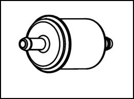
Gasoline filter Check of degradation and damage of fuel pipe. If there is any degradation, damage or fuel leakage, new products should replace the old ones.
Free stroke: 2-6mm Side of the restrictor is the main parts which should be adjusted. Loosen the hold-down nut and rotate to adjust nuts.
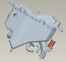
Air filter Change of air filter Disassemble seat cushion
Disassemble backplate of the right fuel tank Disassemble right knee board. Disassemble backplate of the left fuel tank
Disassemble gusset plate of right and left fuel tank backplate
Disassemble bolts; take down air filter. Disassemble filter sponge from air filter.
Check whether the filter sponge is polluted or damaged. If there is pollution or damage, please replace a new one. If there is pollution, please replace and wash.
a) Wash it in the clean washing oil. b) Make it fully dry. c) Soak it in the clean gear oil until soaking well. d) Squeeze out the extra oil in sponge.
If driving under dusty condition or in rainy days frequently, replace the air cleaner earlier. *Attention
Pull out head of spark plug.
Check the burning, pollution and carbon deposit of spark plug.
Clearance inspection of spark plug Gap: 0.7-0.8mm Spark plug type: CR8E (NGK) *Attention
Storage battery
Open seat cushion Disassemble gusset plate of right and left fuel tank backplate. Disassemble air filter cover Disassemble negative wire first and then the positive one. Take out storage battery. Warning!
Install the battery in reverse order of removal. Warning!
Open seat cushion Open roof cover of air filter; disassemble joint wire of storage battery. Measure the battery voltage using a voltmeter. Fully charged: 13.1V Undercharge: 12.3V * Attention
Charging Connection method: Positive pole of battery charger is connected to battery positive lead wire; Warning!
* Attention
Quick recharging: 4.0A
Quick recharging: 30minutes Restrictor Idle speed adjustment * Attention
Warm up the engine and then adjust idle speed. Run the engine and connect engine tachometer. Adjust the throttle cable lock-screw to specified RPM. Idle speed RPM: 1,700ЎА100rpm/min If idle speed RPM is unsteady, or idle speed is not smooth when gently raise engine speed, adjust idle speed adjusting screw again. Cylinder pressure
Disassemble spark plug. Install roof cylinder pressure gage. Fully open accelerator; start engine to measure cylinder pressure. Drive Chain Slackness Service life of drive chain relies on proper lubrication and adjustment. If not maintained in a proper way, advanced abrasion will come out in drive chain or chain wheel. In the harsh using conditions, maintain frequently is necessary.
Stand vertically the motorcycle on the flat ground and check drive chain slackness a. Lubrication of drive chain Use drive chain grease first; buy drive chain grease or engine oil or other lubricating oil. Soak every chain joint to make grease through link plateЎўmeltЎўlining and rolling. *Attention DonЎЇt install new chain on the damaged chain wheel or install damaged chain on new chain wheel. Chain and chain wheel should be in good condition, or the changed chain or chain wheel will be damaged soon. Clearance: 10-20mm
Please adjust free travel of front brake handle in the following way: (1) Loose mandrill to lock nut1. (2) Twist in or out the mandril2 to adjust free travel of front brake handle, after adjusting free travel to 10-20mm. (3) Install mandril1 tight and lock nut1
Measure the clearance of rear brake at the tip of front brake handle.
Clearance: 10-20mm Please adjust free travel of back brake footstep in the following way: (1) Loose mandrill to lock nut1. (2) Twist in or out the mandril2 to adjust free travel of front brake handle, after adjusting free travel to 10-20mm.
Front/back brake shoeЎЇs abrasive wear
When braking exactly, check oil level from oil immersion lens. If liquid level of brake fluid is below the arrow position in the right picture, brake shoe should be replaced immediately by a new one.
Back brake shoeЎЇs abrasive wear When braking exactly, look oil cup to check oil level of brake fluid. If the level is below MIN, brake shoe should be replaced as soon as possible.
Headlight
Clutch
Bolt/Nut/Fastening Part Inspect bolts, nuts and fastening parts at every part of the motorcycle for looseness.
Wheel Rim/Tyre Check if there is crack, nails and similar sharp objects, and other injuries on the tyres.
Inspect pneumatic pressure of tyres.
* Attention
Front liquid brake block
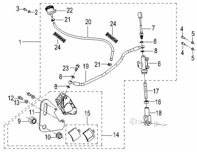
ўЕ Inner hexagon screw M8*35 ўЖ Gasket 8 ўЗ Front liquid brake block units ўИ Brake cylinder units ўЙ Brake shoe units ўК Sealing gasket ўЛ Erection bolt in oil tube ўМ Brake house units ўН Oil pump units ўО Handle ўП Thin nut M6 ўР Handle screw ўС Fixed cover ўТ Bolt M6*25 ўУ Brake switch units ўФ Countersunk flat Phillips heads for exposed screws M4*12 ўХ Mandrill ўЦ Self-locking nut M6
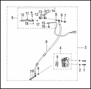
ўЕ Rear liquid brake block units ўЖ Gasket 6 ўЗ Inner hexagon screw M6*16 ўИ Inner hexagon screw M6*16 ўЙ Gasket 6 ўК Oil pump assembly ўЛ Brake switch assembly ўМ Seal ring ўН Lining I ўОLining II ўП Connecting plate ўРInner hexagon screw M8*20 ўСGasket 8 ўТ Brake cylinder B ўУ Friction plate units ўФ Nut M6 ўХ Draw bar ўЦ Draw handle ўЧ Brake hose unit ўШ Oil tube (21) Hoop (22) Oil cup units (23) Hexagon flange head tapping screw (24) Protecting spring I Braking System Maintenance instruction--------------------1.1 Fault diagnosis-------------------------------1.2 Front hydraulic disc brake----------------- 1.3 Rear drum brake-----------------------------1.4 1.1 Maintenance Instruction Precautions on operation * Attention
* Please check braking system before driving your motorcycle.* 1.1.1 Specifications
1.1.2 Torsion force Former brake disc retaining bolt 5-10NЎ¤m Under the brake fluid before pump installation bolt 22-34NЎ¤m Liquid brake oil pump before installation bolt 5-10NЎ¤m Front wheel spindle 100-113NЎ¤m
Front wheel head bolt 5-10NЎ¤m The brake disc retaining bolt 5-10NЎ¤m Liquid brake pump installation after the bolt 22-34NЎ¤m Back oil pump installing bolts liquid brake 5-10NЎ¤m Back wheel spindle 100-113NЎ¤m 1.2 Fault diagnosis 1.2.1Brake in ill performing services l Brake without adjustment well l Abrasive wear of brake shoe units and liquid brake plate l Improper installment of brake shoe units l Pollution of liquid brake plate of brake shoe units 1.2.2 Brake reaction slowly or handle is tight l Brake without adjustment well l Abrasive wear of brake shoe units and liquid brake plate Improper installment of brake shoe units 1.2.2 Brake with abnormal sound l Abrasive wear of brake shoe units and liquid brake plate l Pollution of liquid brake plate of brake shoe units 1.2.4 Braking handle/footstep is soft or light l Air in hydraulic system l Leakage of hydraulic system l Braking footstep/plate is dirty l Sealing abrasive wear of caliper piston l Abrasive wear of braking footstep/plate l Caliper is dirty l Caliper can not slide well l Lack of brake fluid l Block of brake fluid pipe l Bending/incompletion of caliper piston l Bending/incompletion of master cylinder piston l Master cylinder piston is dirty l Braking handle/footstep is curving 1.2.5 Brake gets stuck or is pulled to one side l Braking footstep/plate is dirty l Deviation of wheels l Block or restriction in brake hose joints l Bending/incompletion of braking plate l Caliper slides abnormally 1.2.6 Brake drag l Braking footstep/plate is dirty l Deviation of wheels l Abrasive wear of braking footstep/plate l Bending/incompletion of braking plate l Caliper slides abnormally 1.2.7Brake handle/footstep is hard l Block or restriction of brake system l Adhere/abrasive wear of caliper piston l Caliper slides abnormally l Block/restriction of brake fluid pipe l Sealing gasket abrasive wear of caliper piston l Adhere/abrasive wear of master cylinder piston l Braking handle/footstep is curving 1.3 Front Hydraulic Brake
* Attention
Loosen brake cylinder units and fix bolts. Disassemble brake cylinder units from front damper Disassemble the following units from front damper:
Front liquid brake block 1. Braking shoe 2. Front brake block oil pipe 3. Brake cylinder units * Attention
Disassemble front axle Take down front axle Disassemble front liquid brake block from front wheel
1.3.2 Check Check the abrasive wear condition of brake shoe. Replace it when necessary. Measure brake shoeЎўbrake plate and then write down the maximum number. Measure the thickness of brake shoe. Specification Diameter of front liquid brake plate: ¦Х280mm *Attention
* Attention
1.3.3 Installment Install front wheel Install front liquid brake oil pipe and brake cylinder units Do not get grease on brake shoe * Attention
Fasten bolts to the setting torsion force Torsion force: Former brake disc retaining bolt 5-10NЎ¤m Under the brake fluid before pump installation bolt 22-34NЎ¤m Liquid brake oil pump before installation bolt 5-10NЎ¤m Front wheel spindle 100-113NЎ¤m Front wheel head bolt 5-10NЎ¤m
1.4.1 Disassembly Disassemble back brake oil pump units Disassemble back brake cylinder units Disassemble back wheel Disassemble bake disc from back wheel hub
NoteЈє Specification Diameter of front liquid brake plate: ¦Х280mm *Attention
If the thickness of brake plate and brake shoe are less than maintenance value or polluted by grease, please replace them.
* Attention
Install front wheel Install front liquid brake oil pipe and brake cylinder units Do not get grease on brake shoe * Attention
Fasten bolts to the setting torsion force Torsion force: Former brake disc retaining bolt 5-10NЎ¤m Under the brake fluid before pump installation bolt 22-34NЎ¤m Liquid brake oil pump before installation bolt 5-10NЎ¤m Front wheel spindle 100-113NЎ¤m Front wheel head bolt 5-10NЎ¤m No oil stain shall be on brake shoe and brake disk. If any, use brake cleaner fluid. *Attention
Body outer panels
1 Front and right turn light 2 Front and left turn light 3 Front night-light fixed position 4 Pod 5 Right mounting plate of pod 6 Left mounting plate of pod 7 Headlight 8 Instrument assembly 9 Front splash guard 10 Right and left oil tank guard plate gusset piece 11 Right back plate 12 Left back plate 13 Right and left back plate 14 Left dale 15 Back plate of left oil tank 16 Front of back splash guard 17 Right and left guard plate gusset piece 18 Seat cushion 19 Left kneelet 20 Right kneelet 21 Back plate of right oil tank 22 Right decorative plate 23 Back license plate lamp 24 Back and left turn light 25 Back and right turn light 26 Back splash guard 27 Back splash guardўт 28 Back taillight 29 Back of back splash guard II Vehicle Housing Disassemble body as the following order:
rearview mirror Ўъfront pod Ўъinstrument support Ўъinstrument Ўъback pod Ўъfront splash guard Ўъseat cushion Ўъdecorating plate of left and right front back plate Ўъleft and right front back plateЎъ front and back junction plate of right and left back plateЎъ bottom coverЎъ left and right back plate of oil tank Ўъ right and left back guard board Ўъright and left step tread ЎъtaillightЎъ back splash plate Ўъ back license tag support * Attention Do not damage exterior parts during assembly and disassembly. Do not damage the jaws on the exterior parts of the vehicle during assembly or disassembly. Align built-in panel and cover plate to their grooves respectively. Correctly install paw of each part during combination. Do not damage the fittings during exterior part installation.
Front wheel
1 Front wheel axleM14*1.5*219 2 Odometer wheel gear units 3 Front wheel sealed units 4 Front wheel middle shaft sleeve 5 Cycle valve6 vacuum tyre 100/80-17 7 Front wheel ring 8 Liquid brake plate erection bolt 9 Front wheel left shaft sleeve 10 Antifriction bearing 6202-2RS 11 Front brake plate Tightening torque Tools Direction handle fixed screw 22-29 NЎ¤m Bearing disassembly pole Front axle 37-44 NЎ¤m 3.2 Fault diagnosis 3.2.1 Direction handle moves hard l Direction handle is out of order or damaged l Bearing failure of direction handle l Faucet bearing rating nut is too tight l Tire pressure is not enough 3.2.2 Wobbly Direction Handle l Damaged handle bearing l Not enough tyre pressure. l Front fork bent, front wheel shaft bent. l Distorted and crooked front wheel tyre. 3.2.3 Wobbly Front Wheel l Distorted wheel rim l Worn front wheel bearing l Defective front tyre l Unbalance of tyre or wheel 3.2.4 Difficult Rotation of Wheel l Breakdown of front wheel bearing l Braking breakdown of brake l Breakdown of wheel and axle l Bending of front wheel 3.2.5 Noisy Front Shock Absorber l Lack of liquid in shock absorber l l Loosened bolts on the shock absorber. 3.2.6 Operated to one side only or walking not in straight line l unbalance of both crossesЎЇ adjustment l bending of shock absorber l bending of wheels l inaccuracy of wheelsЎЇ installment l bending of car frame l illness of axle l illness of swing arm central shaft units 3.2.7 Front shock absorber is soft l lack of liquid in shock absorber l insecure of spring in shock absorber l tyre pressure is too low 3.2.8 Front shock absorber is hard l inadequacy of liquid weight l block of shock absorber liquid pipe Front wheel 3.3.1 Disassembly Support the bottom of body to float front wheel Disassemble bolt and take down front splash guard and odometer guide line. Disassemble front brake hose Disassemble front axle jam nut Disassemble front axle Disassemble front wheel Disassemble oil seal with oil seal stripping attachment and bearing with bearing stripping attachment. *Note: dismounting picture is on page 41 of this manual 3.3.2 Inspection
Place the shaft onto a V block and measure its eccentricity with a dial gauge.
Attention
Install front axle and then lock tight. * Note: the dismounting picture is on page 41 of this manual Torsion force Front axle: 37-44 NЎ¤m 3.4 Direction handle
Disassemble direction handle sheath and rearview mirror units Disassemble front brake handle and left handle units Take down accelerator seats units and right grip units Take down accelerator cable units Take down left direction handle cover Take down clutch line units and ventilation door line units Take down handle fixed bolt and handle. 3.4.2 Installment Install in the order which is against disassembly Fixed bolt Torsion forceЈє22-29NЎ¤m
3.5.1 Disassembly Disassemble front splash guard Disassemble front wheel Disassemble brake hose and autometer wire Disassemble front shock absorber Disassemble diversion fixed nut Disassemble direction handle Tools: Direction handle fixed bolt wrench Fixed nut wrench * Attention:
3.5.3 Installation Tools: Locknut wrench
Rotate the front fork left and right to be sure of its smoothness and there shall be no looseness.
Steps: Install direction handle. Install front shock absorber. Install front wheel. Rear wheel
Loosen rear axle nut Disassemble rear axle nut and take down chain from chain wheel seat Disassemble rear axle Disassemble rear wheel
4.3.2 Inspection
Put axle on V-style seat and measure its eccentricity ratio with dial indicator Rear wheel shaft locknut Tightening torque: 100-113NЎ¤m
4.4.1 Disassemble rear shock absorber Disassemble body guard board Disassemble rear splash guard Disassemble tool box Disassemble air filter Disassemble rear wheel shock absorber fixed bolt Take down rear shock absorber
4.4.2 Rear Shock Absorber Inspection Visual inspection of shock absorber to check whether there is damage
Check the following items: ЎЄbending or damage of shock absorber pipe ЎЄout of shape or oil leakage of shock absorber ЎЄabrasive wear or damage of block rubber ЎЄdamage of spring
Check damage or abrasive wear of other parts Replace shock absorber if necessary
4.4.3 Install Rear Shock Absorber Install the rear shock absorber in the reverse order of removal. Install upper locknut and lower mounting bolt on the rear shock absorber Tighten them to specified torque.
Torsion force: Upper hold-down nut: 37-44NЎ¤m Bottom hold-down nut: 37-44NЎ¤m
4.5.1 Remove Rear Swing Arm Disassemble chain guard board Disassemble chain tension wheel and rear axle Disassemble rear wheel and rear shock absorber Disassemble rear swing arm installment axle Take down rear swing arm weld assembly
Check rear swing arm installation shaft. Rotate the shaft on a flat surface or measure it with a dial gauge. If it is bent, replace it. * Attention
Wash in solvent the components for rear swing arm installation shaft. Check sleeve assembly and intermediate sleeve of rear swing arm. If they are damaged, replace them.
4.6 Drive Chain 4.6.1Ј® Disassembly Lay motorcycle on the flat ground and fasten Disassemble shift lever swing arm, left rear cover and drive chain Disassemble rear wheelЎўchain shield and drive chain
Wash drive chain and put it into kerosene. Brush dust and then take it out from kerosene and dry it out.
Check drive chain. Wash, lubricate and replace it if it is hard.
Check drive chain and driven chain wheel. Replace chain wheel when 1/4 gear teeth are worn. Replace it when gear teeth is bending.
Check wheel axle. Replace when there is bearing gap in hub or unbalance of rotation. Check oil seal and replace when there is abrasive wear or damage. Attention
At last, screw down locking nut
Do the verse steps as disassembly Install drive, hull, rear shock absorber(left), rear wheel and drive chain sleeve Adjust slackness of drive chain and free travel of brake footstep. If the slackness is too small, engine and other important parts will overload. Make sure the slackness in the scope of limit value. Charging system
Testing device Multimeter 5.2 Fault Diagnosis No power unstable power Battery over discharged Lead wire of battery is poorly contacted. Lead wire of battery is not connected. Discharging system is of poor contact. Fuse is broken. Lighting system is of poor contact or short circuit. Power switch is poorly contacted. Low voltage Poor charging system Battery is poorly recharged. Wire connector is of poor contact, short circuit or short line. Poor contact. Defective voltage and current adjuster Poor charging system Magneto does not work well. Bad voltage and current adjuster
Storage Battery
Open seat cushion Disassemble left guard board Disassemble negative guide line first and then the positive guide line Take out storage battery
Warning!
Install the battery in the reverse order of removal.
*Attention
Check of charging situation (open-circuit voltage) Open sear cushion Open air filterЎЇs cover and disassemble storage battery joint guide line
Measure voltage between terminals of the battery Fully charged: 13.1V Quick charging: 4.0A Quick recharging: 30minutes VI Ignition System Preparatory data ----------------6.1 Ignition coil ------------6.5 Fault diagnosis -----------------6.2 Trigger -----------------6.6 Ignition system inspection ---- 6.3 Charging coil---------- 6.7 CDI assembly ------------------6.4 Preparatory Data Precautions on operation 1. Ignition system inspection: please perform inspection in the sequence listed in the fault diagnosis table. 2. Ignition system uses electronic-type automatic timing device, which is solidified in the CDI assembly, so it is unnecessary to adjust the ignition time. 3. Ignition system inspection: please perform inspection in accordance with the sequence listed in the fault diagnosis table. 4. Ignition system CDI shall not be dropped and hung, or heavily knocked (this is also the main reason for its failure). Pay special attention to this while removing it. 5. Most of the ignition system problem due to poor contact of sockets. Please check first if parts of the connector are well contacted. 6. Check if heat value of spark plug is proper. Improper spark plug may result in unsmooth engine running or burn of spark plug. 7. The maximum voltage is taken to introduce inspection items in this Part. Inspection methods for impedance value of ignition coil are also recorded and judged. 8. Check ignition switch according to the continuity test table. 9. Remove alternator and stator on operation instructions. Preparatory data
Tools Multimeter
Fault Diagnosis Spark plug not sparking
* Attention
Connect a high-voltage shunt or an ammeter with input impedance higher than 10M¦ё 10CV to the multimeter. 6.3.1 Primary voltage of ignition coil If an old spark plug is removed and replaced with a good one, ground it with engine.
Disassemble central cover Connect lead wire of ignition coil; a shunt is connected between the terminal (black/white) of primary coil and the grounding vehicle block. Press starting motor button or kick starting pedal to measure primary peak voltage of ignition coil. Min. voltage: over 95V.
6.3.2 Charging coil * Attention
|
|||||||||||||||||||||||||||||||||||||||||||||||||||||||||||||||||||||||||||||||||||||||||||||||||||||||||||||||||||||||||||||||||||||||||||||||||||||||||||||||||||||||||||||||||||||||||||||||||||||||||||||||||||||||||||||||||||||||||||||||||||||||||||||||||||||||||||||||||||||||||||||||||||||||||||||||||||||||||||||||||||||
|
|
Последнее изменение этой страницы: 2016-04-08; просмотров: 951; Нарушение авторского права страницы; Мы поможем в написании вашей работы! infopedia.su Все материалы представленные на сайте исключительно с целью ознакомления читателями и не преследуют коммерческих целей или нарушение авторских прав. Обратная связь - 3.129.13.201 (0.835 с.) |
 After disassembly and before measuring friction, please clean the components and blow them with compressed air.
 ЎЄBending or Warping are forbidden in operation, otherwise tough operation or advanced damage will be caused.
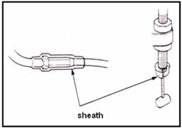 Plastic parts may age and deteriorate, which are apt to be damaged by solvent or oil. Check before re-installation and replace if necessary.
 To loose component with many assembling units, it shall start from external to internal and loosen smaller assemblies first.
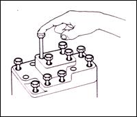 Length of bolts and screws are different for assembly components and protecting plates. They shall be installed at correct positions. If confused, just put the bolt in the hole and see if it matches.

 Disassembly of ball bearing: use a tool to push against one or two (internal and external) bearing races. If the force works only on one bearing race (whatever internal or external), it may be damaged when the bearing is disassembled, in which case, it must be replaced
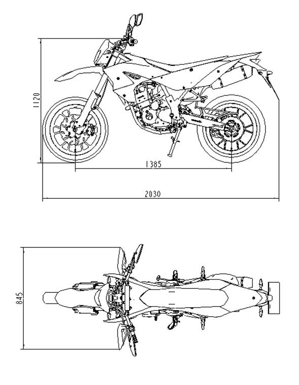
 Check engine oil level again.
 Warning!
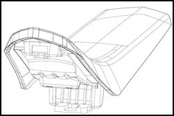

 Disassemble left knee board.
 Disassemble air filter cover; fix bolts; take down the cover.
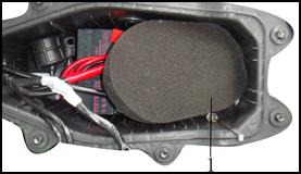
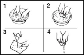 How to wash the filter sponge:
 Replacing Time
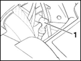 Spark plug
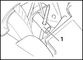 Disassemble spark plug with spark plug sleeve.
 If the conditions above happen, please clear with spark plug scavenger or steel brush.
 Disassembly of storage battery
 Check of the charging state (closed circuit voltage)
 Recharging time: Standard: 10-15hours
 Operation when engine is warming.
 Rear brake clearance
 (3) Install mandril1 tight and lock nut1
 Front brake shoeЎЇs abrasive wear
 Adjustment
 Optical axis adjustment of headlight is loosening headlight spinning adjusting bolt and then rotating.
 Start engine and increase rotation speed gradually to check running condition of clutch. If motorcycle can not walk or engine shuts down, check clutch block. Replace a new one when necessary.
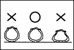 If it is loose, tighten it to specified torque.
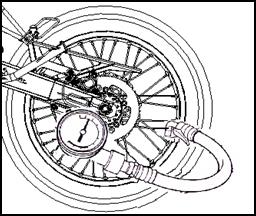

 1.3.1 Removal
 If the thickness of brake plate and brake shoe are less than maintenance value or polluted by grease, please replace them.
 1.4 Back liquid brake
 1.4.3 Installment


 Friction sound of shock absorber protecting plate.
 3.3.2.1 Shaft Bow Inspection
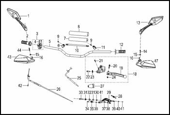 3.4.1 Disassembly
 3.5 Front fork
 4.3.1 Disassembly
 4.3.2.1 Check the bending of axle
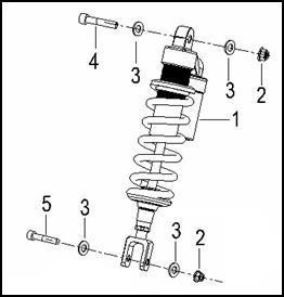 4.4 Rear Shock Absorber
 4.5 Rear Swing Arm
 4.5.2 Rear Swing Arm Inspection
 4.5.2Ј® Inspection
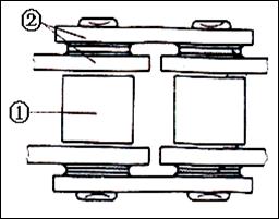 Check rattleer1and side panel2. replace drive chain when damaged or abrased.
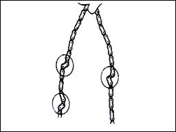 Lubricate drive chain. Buy it from store
 4.5.4 Installment

 5.3.1 Battery Removal
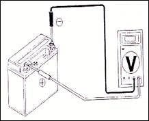
 6.3 Ignition System Inspection
 * Attention
 *Attention