Заглавная страница Избранные статьи Случайная статья Познавательные статьи Новые добавления Обратная связь FAQ Написать работу КАТЕГОРИИ: ТОП 10 на сайте Приготовление дезинфицирующих растворов различной концентрацииТехника нижней прямой подачи мяча. Франко-прусская война (причины и последствия) Организация работы процедурного кабинета Смысловое и механическое запоминание, их место и роль в усвоении знаний Коммуникативные барьеры и пути их преодоления Обработка изделий медицинского назначения многократного применения Образцы текста публицистического стиля Четыре типа изменения баланса Задачи с ответами для Всероссийской олимпиады по праву 
Мы поможем в написании ваших работ! ЗНАЕТЕ ЛИ ВЫ?
Влияние общества на человека
Приготовление дезинфицирующих растворов различной концентрации Практические работы по географии для 6 класса Организация работы процедурного кабинета Изменения в неживой природе осенью Уборка процедурного кабинета Сольфеджио. Все правила по сольфеджио Балочные системы. Определение реакций опор и моментов защемления |
Abnormal sound in the crankcaseСодержание книги
Поиск на нашем сайте
There are parts scattered or broken inside the crankcase Engine stalling Clutch is stuck Shifting difficulty Separation between the clutches is not complete Poor returning spring of the clutch Locked grove of the gearshift hub worn Crankcase
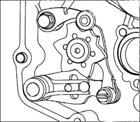
Release the fastening bolts of the left cover to remove the left cover.
Release the locking nuts of the flywheel using electric or pneumatic tools. Allocate the flywheel assembly (including the star wheel) to remove the electric idle gear. Remove the gasket.
Loosen the fastening bolts to remove the right cover of the crankcase, gasket and locating pin.
Clutch
Loosen the five bolts of the pressure plate according to the diagonal cross mode. Remove the clutch springs, spring washers, pressure plate, bearing washer, surface needle roller bearing and bearing pedestal, clutch separation shaft sleeve and so on.
Use a special tool to screw off clutch locknut. Remove locknut and washer. Remove clutch center bracket. Remove clutch drive and driven friction plates.
Remove the thrust washer. Remove housing assembly.
Install clutch in the reverse order of removal. Disassemble Clutch
1 Bolt 2 Spring washer 3 Clutch spring 4 Pressure plate 5 Bearing washer 6 Surface needle bearing 7 Clutch separation shaft sleeve 8 Jam nut 9 Locking washer 10 Friction plate assembly 11 Driven plate 12 Clutch driven hub 13 Thrust washer 14 Clutch driving drum assembly 15 Internal separation mandrilЎ 16 Needle roller bearing 17 Bushing 18 Internal separation mandril¦т 19 Separation drag bar weld assembly 20 Clutch assembly
If there is a lot for fix and adjustment, replace it.
Check if teeth of pressure plate and center bracket are injured. If they are, replace them.
Measure the free length of pressure spring. Allowable limit: replace it if below 29.7mm.
Measure the thickness of friction plate with a vernier caliper.
Allowable limit: Replace it if above 0.2mm.
Allowable limit: Replace it when it is below 1.8 mm. Crankshaft connecting rod combination and variable speed chamber
Gearshift mechanism
Remove the stop arm. Remove the gearshift locating plate.
Remove the parts.
Inspection The gearshift plate should be pulled back flexibly without clamping stagnation before being disassembled. Check whether the gearshift plate and the gearshift shaft combination are worn. If badly worn, replace it. Check whether the gearshift locating plate is worn. If badly worn, replace it. Check whether the gearshift shaft is bent. If excessively bent, replace it. Check whether the force of the return spring is weakened, and replace it if necessary.
Remove the nuts of the countershaft to remove the sprockets and bushings. Loosen the mould assembling bolt. Separate the crankcase. Attention: There should be no damage on joint case surface. Remove the left case.
Crankcase connecting rod combination Disassemble
Measure the clearance between the big ends of connecting rod. Allowable limit: 0.5 mm.
Measure the clearance in the X-Y direction of the big ends of connecting rod.
Measure the jumping of the crankshaft. Allowable limit: 0.03 mm.
Set aside the shifting fork shaft.
Remove the gearshift fork.
Measure the outer diameter of the shifting fork shaft. Allowable limit: 9.96mm.
Allowable limit: 10.05mm.
Measure the thickness of the shifting fork.
Allowable limit: 41.75mmЎЈ Measure the width of the locked groove of the gearshift drum. Allowable limit: 5.7mm.
Remove the layshaft assembly.
|
||||||||||||||||||
|
|
Последнее изменение этой страницы: 2016-04-08; просмотров: 541; Нарушение авторского права страницы; Мы поможем в написании вашей работы! infopedia.su Все материалы представленные на сайте исключительно с целью ознакомления читателями и не преследуют коммерческих целей или нарушение авторских прав. Обратная связь - 216.73.216.3 (0.007 с.) |

 Disassemble the left cover of the crankcase
 Release the fastening bolts of the starting engine to remove the starting engine.


 Removal
 Removed components refer to exploded view.
 Check if there are burs or broken parts on the housing groove of clutch. If there are, fix and adjust with a file.

 Allowable limit: Replace it when below 2.5mm.
 Check the flatness of the driven friction plate with the plug gauge.
 measure the thickness of the surface needle roller bearing.


 Disassemble
 Remove the gearshift shaft combination
 (Please refer to the exploded view of the
  Loosen the nuts and washer of the right crankshaft to remove the clutch drive gear using electric or pneumatic tools.
 Remove the trunnion shaft combination and crankcase connecting rod combination from the right crankcase.
 Attention: There should be no damage on joint case surface.
 Inspection
 Allowable limit: 0.008-0.018mm.
 Check whether there is abnormal sound or loose for the revolution of the crankshaft bearing. If any, replace the crankshaft assembly.
 Remove the gearshift drum.
 Inspection
 Measure the inner diameter of the shifting fork hole.
 Allowable limit: 4.6mm
 Measure the outer diameter of gearshift drum.
 13.7 Variable speed chamber
 Remove the spindle assembly.