Заглавная страница Избранные статьи Случайная статья Познавательные статьи Новые добавления Обратная связь FAQ Написать работу КАТЕГОРИИ: ТОП 10 на сайте Приготовление дезинфицирующих растворов различной концентрацииТехника нижней прямой подачи мяча. Франко-прусская война (причины и последствия) Организация работы процедурного кабинета Смысловое и механическое запоминание, их место и роль в усвоении знаний Коммуникативные барьеры и пути их преодоления Обработка изделий медицинского назначения многократного применения Образцы текста публицистического стиля Четыре типа изменения баланса Задачи с ответами для Всероссийской олимпиады по праву 
Мы поможем в написании ваших работ! ЗНАЕТЕ ЛИ ВЫ?
Влияние общества на человека
Приготовление дезинфицирующих растворов различной концентрации Практические работы по географии для 6 класса Организация работы процедурного кабинета Изменения в неживой природе осенью Уборка процедурного кабинета Сольфеджио. Все правила по сольфеджио Балочные системы. Определение реакций опор и моментов защемления |
Taillight/license plate lamp/rear turn-lamp bulb replacementСодержание книги
Поиск на нашем сайте
Disassemble bolt and taillight shade. Disassemble bulb from socket
8.5.2 Installment Install bulb back in the verse order of disassemble.
8.5.3 Rear turn signal lamp replacement 8.5.3.1 Disassembly Disassemble bolt and taillight shade. Disassemble bulb from socket 8.5.3.2 Installment Install bulb back in the verse order of disassemble.
Remove rear mirror. Take down the handle hood and pull out waterproof connector. Remove the bolts. Remove meter housing Remove the instrument. Install the instrument orderly in the reverse order of removal.
Main Switch
Disassemble front guard board Disassemble master switch guide line joint Break over test of joint side
8.7.2 Master switch replacement Disassemble body front guard board Disassemble fixed bolt and take down master switch fixed seat Disassemble fixed bolt and replace master switch. Horn
Disconnect wire to the electric horn. Connect lead wire of horn with the battery. When the electric horn sounds, it indicates the horn is in good condition.
Remove protecting plate of steering handle. Screw off mounting bolt on the brake lever and take down the bracket. Remove bracket for the rear brake lever. Remove throttle handle and bolts. Take down throttle handle from the handle and remove the throttle cable.
Remove locknut on the handle and take down the handle.
Engine Inspection and Maintenance Table of tightening torque for fastening parts used in engine
Lubricating System Chart
IX Lubricating System Preparatory data--------9.1 Fault diagnosis---------9.2 Oil engine pump-------9.3 Preparatory Data Function of lubricating system: Function of engine lubricating system is to supply lubricating oil to friction surfaces of engine parts so that dry surface friction will turn to liquid friction between plasmids of lubricating oil. It is used to reduce wear of component, cool components of higher heat, absorb impact from bearing and other parts, weaken noise, increase tightness between piston ring and cylinder wall, clean and take away impurities from surface of component, etc. Precautions on Operation When engine oil pump is removed, clean carefully all the components and purge them with high-pressure gas. During engine oil pump removal and installation, pay attention not to drop anything into the crankcase.
Table of standard values of baseline projects and allowable limit
Fault Diagnosis Reducing engine oil Natural consumption Oil leakage Engine burnt No oil pressure or too low oil pressure Oil way clogged Oil Pump Disassembly Remove the right cover, the clutch, and the retaining ring, and then remove the oil pump gears and oil pump transition gear;
Remove the fixed pin, the screw and the pup cover, and disassemble the oil pump;
Allowable limit: 0.15 mm
Check the clearance between the outer rotor Allowable limit: 0.15 mm
Check the clearance between the rotor ends Allowable limit: 0.15 mm
Assemble Engine Oil Pump As shown in the following figure
1 Oil suction pump assembly 2 Oil pressure pump assembly 3 Retaining ring 4 Gasket 5 Oil pump gear 6 Fixed pin 7 Oil suction pump shaft 8 Pin 9 Bolt M6x16 10 Oil pump cover 11 Inner rotor 12 Outer rotor 13 Oil pressure pump shaft 14 Oil pump cover 15 Inner rotor 16 Outer rotor 17 Gasket 18 Oil pump transition gear 19 Transition gear shaft
* Attention: After assembly, inner and external rotors shall rotate smoothly and be out of nimbleness.


Install the oil pump in the reverse order of removal. X Cooling system Preparatory data---------------------------10.1 Fault diagnosis-----------------------------10.2 Water pump---------------------------------10.3 Preparatory data Functions of cooling system: It can build some channels which can allow liquid circulation inside the cylinder and the inner wall of the cylinder cover; a special radiator is set outside the engine body so that the forced circulation of cooling water can be made through water pump and pipeline, and then the heat of the engine can be released to cool it through air blowing the surface of the cooling fin of the radiator at high speed. Fault diagnosis Water leakage Seal ring damaged Pimp body broken Water pipe breakage
|
|||||||||||||||||||||||||||||||||||||||||||||||||||||||||||||||||||||||||||||||||||||||||||||||||||||||||||||||||||||||||||||||||||||||||||||||
|
|
Последнее изменение этой страницы: 2016-04-08; просмотров: 387; Нарушение авторского права страницы; Мы поможем в написании вашей работы! infopedia.su Все материалы представленные на сайте исключительно с целью ознакомления читателями и не преследуют коммерческих целей или нарушение авторских прав. Обратная связь - 3.138.178.162 (0.009 с.) |

 8.5.1 Disassembly
 8.6 Instrument
 8.7.1 Inspection
 Inspection
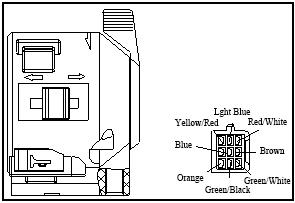 8.9 Handle switch


 Check the radial clearance between the inner