Заглавная страница Избранные статьи Случайная статья Познавательные статьи Новые добавления Обратная связь FAQ Написать работу КАТЕГОРИИ: ТОП 10 на сайте Приготовление дезинфицирующих растворов различной концентрацииТехника нижней прямой подачи мяча. Франко-прусская война (причины и последствия) Организация работы процедурного кабинета Смысловое и механическое запоминание, их место и роль в усвоении знаний Коммуникативные барьеры и пути их преодоления Обработка изделий медицинского назначения многократного применения Образцы текста публицистического стиля Четыре типа изменения баланса Задачи с ответами для Всероссийской олимпиады по праву 
Мы поможем в написании ваших работ! ЗНАЕТЕ ЛИ ВЫ?
Влияние общества на человека
Приготовление дезинфицирующих растворов различной концентрации Практические работы по географии для 6 класса Организация работы процедурного кабинета Изменения в неживой природе осенью Уборка процедурного кабинета Сольфеджио. Все правила по сольфеджио Балочные системы. Определение реакций опор и моментов защемления |
Bases of creation of the determined mathematical models of the CTS elementsСодержание книги
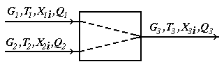
Поиск на нашем сайте As it was told above, the determined or physical and chemical mathematical models reflect the theoretical regularities of processes proceeding in the CTS elements. In case of development of such models use the mass conservation laws and energies, laws of transfer of substance, energy and an impulse, regularity of kinetics of the proceeding chemical reactions, hydrodynamics of flows, etc. In connection with complexity of real engineering procedures, in case of development of their mathematical models usually enter a number of the assumptions simplifying the description of real process, and allowing to apply the block principle of creation of models according to which the mathematical description of an object is received in general as set of descriptions of the separate elementary processes proceeding in the considered object. We will cover the basics of creation of the determined mathematical models of processes on some examples. Mixer module. The module of the mixer is one of the simplest modules. According to an initial task, two flows of substance having expenses of G1 and G2 (mol/sec.), temperatures of T1 and T2 (a hail. J), structures of X1i and X2i (molar shares), warmth of Q1 and Q2 (W) move in the mixer from where there is one flow with G3 expense, T3 temperature, structure of X3i and warmth of Q3 (see Fig. 4.11).
Fig. 4.11. Scheme of the module of the mixer The physical and chemical model of the mixer is intended for calculation of material and thermal balances of process of mixture of two flows of substance. There are modules for mixture of several flows of substance, but they are expanded modification of the mixer for mixture of two flows. Usually in case of creation of the simplified determined model some assumptions are accepted. For the mixer, assumptions will be the following: 1. The structure of a flow in the device corresponds to the mode of ideal mixture; Otherwise, the flow at the exit of the mixer will be not completely mixed, and, it will be in that case necessary or to complicate model taking into account hashing coefficient, or to complicate model taking into account hydrodynamics of flows in the device. It can be not justified on specific costs of time for development of model, and in case of incomplete accounting in model of all proceeding physical and chemical phenomena to lead to considerable mistakes. 2. Mixture process – adiabatic, isn't considered warmth of mixture; Otherwise it is necessary to consider processes of a supply and withdrawal of warmth, and also the warmth of mixture which is marked out in case of mixture of substances (in particular cases, in thermal balance of the mixer it is required to consider warmth of mixture). 3. All flows have one phase condition; Otherwise the model will need to be complicated considerably since it is necessary to use the mixer having 2 or 3 output flows (gas, liquid and firm) since one flow it is impossible to express at the same time various phase conditions, it will be necessary to consider phase balance in system firm - liquid-gas, and conditions of its establishment, and also thermal balance of processes of establishment of phase balance. 4. Pressure of entrance and output flows – identical;
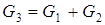
In case of change of pressure there can be conditions leading to change of a phase condition. In case of observance of all assumptions stated above we will consider the equations entering a basis of the mathematical description of model of the mixer. The general equation of a material balance will register:
With use of the equation of material balance for substance it is possible to calculate structure of an output stream:
In case of creation of a material balance special attention is required to be paid on units of measure of expenses and structures. It is usually recommended to use a molar expense [mol/sec.] and structure [% mol.] or mass expense [kg/sec.] and structure [%масс.] or, in case of mixture of gas flows, a volume expense under normal thermodynamic conditions (0OC and 1 atm), i.e. [nm3/sec.], and volume structure [%об.]. It should be noted that when calculating the structure of a flow is usually used not as a percentage, and in shares (the amount = 1), and use of various units of measure for an expense and structure is inadmissible. The general equation of thermal balance will register:
At unknown warmth of a stream, it can be calculated on the basis of material balance on the equation:
where SP – a specific isobaric thermal capacity of a stream (mix of substances) which pays off by the rule of additivity:
where SPi – an isobaric thermal capacity of i-go of a component of a stream which can be calculated on the equation:
coefficients of a which b, c and d for i-go of substance undertake from the reference book. Temperature of an output stream pays off by method of iterations:
Divider module. The module of a divider is one of the simplest modules. According to an initial task, the substance flow having an expense of G1 (mol/sec.), T1 temperature (a hail. J), structures of X1i (molar shares) and warmth of Q1 (W) moves in a divider from where there are two flows with expenses of G2 and G3, temperatures of T2 and T3, structures of X2i and X3i and warmth of Q2 and Q3 (see Fig. 4.12).
Fig. 4.12. Scheme of the module of a divider
The physical and chemical model of a divider is intended for calculation of material and thermal balances of process of division of one flow of substance into two flows. There are modules for division of a flow into bigger quantity of flows, but they are expanded modification of a divider on two flows. For a divider, assumptions will be the following: • The structure, temperature and pressure of output flows are equal to structure, temperature and pressure of an entrance flow; • All flows have one phase condition. Two methods of division of a flow are known. For the FIRST method it is required to know an expense of the first leaving flow, and for the SECOND – coefficient of division of a flow. Depending on type of the equipment connected with a divider, both methods can be applied, however the FIRST method has restrictions which are that absolute values, but not relative are used. For example, in the course of calculations, the expense of the entering flow will be less than the set expense of the first leaving flow, i.e. the second leaving flow will have a negative expense that is impossible. The SECOND method stable in calculations since relative values, however, depending on type of the equipment connected with a divider are used, use of the fixed coefficient of division can not correspond to real CTS. For implementation of the FIRST method it is necessary to know: expense of G1 (mol/sec.), T1 temperature (hail. J), structure of X1i (molar shares) and warmth of Q1 (W), also an expense of the first leaving G2 flow. The main equation of a material balance will register:
Proceeding from an assumption, the structure of output streams will be equal to structure of an entrance stream:
Warmth of the leaving flows can be calculated in proportion to expenses of the leaving flows (temperature and structure of the leaving flows are equal to entering) or are calculated based on a material balance on the equation:
where SP – a specific isobaric thermal capacity of a stream (mix of substances) which pays off by the rule of additivity:
where SPi – an isobaric thermal capacity of i-go of a component of a stream which can be calculated on the equation:
coefficients of a which b, c and d for i-go of substance undertake from the reference book. For implementation of the SECOND method of calculation shall be known: expense of G1 (mol/sec.), T1 temperature (hail. J), the structure of X1i (molar shares) and warmth of Q1 (W), is also set coefficient of division of the entering Kf flow (according to designations in Fig. 4.3, Kf = G2/G1). In this case expenses of the flows leaving a divider can be calculated by formulas:
Further, the algorithm of calculation doesn't differ from an algorithm of the FIRST way of the calculation given above.
Heat exchanger module. Unlike modules of the mixer and a divider, the module of the heat exchanger isn't so simple since at change of temperature of streams change of their phase state is possible, and, therefore, when calculating it is necessary to consider such changes. In this regard, for example, only for systems gas-gas, liquid-liquid and gas-liquid distinguish the following models of heat exchangers: • The heat exchanger gas-gas or liquid-liquid without phase transitions (heaters and refrigerators); • The heat exchanger gas-gas or liquid-liquid with phase transition (for system gas-gas it is called the condenser, and for system liquid-liquid – the evaporator, also exists more difficult option when heat from the condensed gas is used for liquid evaporation); Besides, as his design exerts impact on process of calculation of the heat exchanger, for everyone stated above like heat exchangers distinguish the following models: 1. Counter flow ("cold" and "hot" agents meet halfway each other, i.e. a countercurrent); 2. Direct-flow ("cold" and "hot" agents go in parallel, i.e. a direct flow); 3. Crossflow (intermediate option between stated above); 4. One-pass or multiple-pass heat exchangers (in multiple-pass heat exchangers a part of pipes works in the countercurrent mode, and a part – in the direct flow mode, or in the multiple-pass crossflow heat exchanger liquid or gas on pipes can move on the course or against the stream course in interpipe space); 5. Options when one of agents (or both agents) moves due to natural convection which, on intensity of hashing of a stream due to natural convection, in turn share on horizontal and vertical; 6. Mixture heat exchangers ("cold" and "hot" agents directly contact with each other, for example, in the device to a nozzle). And, at last, the heat exchangers differing on an operating mode on: • periodic; • continuous. It should be noted that according to an initial task for the CTS module, it is required to calculate parameters of output streams at the known parameters of entrance streams and parameters of the CTS element (in case of the heat exchanger, at the known area of heat exchange and coefficient of a heat transfer) that corresponds to test calculation of the heat exchanger. However sometimes there is a need to calculate the sizes of the heat exchanger entering CTS. In that case it is necessary to use design calculation of the heat exchanger. As an example we will consider test calculation of the heat exchanger heater for system gas-gas, liquid-liquid or gas-liquid taking into account the following assumptions: • The one-pass shell-and-tube heat exchanger in the stationary mode; • The heat transfer isn't followed by change of aggregate state; • Thermalizes coefficients for "cold" and "hot" streams pays off at the reference temperatures of heat carriers; • The scheme of the movement of streams – counter flow; • Losses of warmth are absent. The scheme of the heat exchanger is submitted in Fig. 4.13.
Fig. 4.13. Scheme of the heat exchanger
According to an initial task, for an entrance "hot" flow GGN expense, TGN temperature, structure of HGN and warmth of QGN is known, for an entrance "cold" flow – GHN expense, THN temperature, structure of HHN and warmth of QHN. Except flow parameters, for the heat exchanger thermalizes coefficients for "cold" and "hot" flows of aX and aG, and the area of a heat transfer of F are known. Because phase transition doesn't happen, the material balance of the heat exchanger will register equalities of expenses and structures of output flows entrance:
According to thermal balance:
or
where, heat transfer coefficient:
where, dCT and lCT – thickness and heat conductivity of a wall "driving force" of a heat transfer:
where DtБ and DtM – big and smaller differences of temperatures on entrances and heat exchanger exits taking into account the mutual course of streams, for example, for a countercurrent: i.e. DtБ = bigger of (TGN - TGC), (THK - THN) [4.22] DtM = smaller of (TGN - TGC), (THK - THN) [4.23]
As temperatures of "hot" and "cold" flows at the exit of the heat exchanger are unknown, it isn't possible to carry out simple calculation therefore, it is possible to recommend carrying out calculation by method of search or minimization according to the following algorithm: Some initial value of temperature of a "cold" flow at the exit from the heat exchanger is set. Usually: THK = TXH+0,1; At the known temperature of a "cold" flow at the exit, its structure and an expense, on a formula [4.11] taking into account formulas [4.12 and 4.13] its heat content of QHK is calculated; Thermal load of the QTP heat exchanger and heat content of an output "hot" flow of QGK is calculated with use of a formula of thermal balance [4.18]; Its temperature (see [4.7]) and a driving force of a heat transfer is determined by the size of heat content of an output "hot" flow of QGK [4.21]; The difference of warmth of the heat transfer calculated in item 3 and on a formula of the main equation of a heat transfer [4.19] is determined; If the difference determined in item 5 is less than set calculation accuracy, then calculation comes to an end. Otherwise temperature of the leaving "cold" flow increases by some value, and calculation repeats with item 2. When using mathematical methods of minimization, it is necessary to add logical conditions on the analysis of crossing of lines of heating/chilling i.e. that temperature of a "cold" flow on an entrance and an exit of the heat exchanger wasn't higher than temperature of a "hot" flow to item 4. In conclusion it should be noted that except the specified algorithm of testing calculation of the heat exchanger, there are other algorithms resulting in similar results. From all variety of the heat exchange equipment, proceeding from entry conditions, the simplest option of the one-pass counter flow shell-and-tube heat exchanger heater without phase transitions and losses was considered above. In case of phase transitions calculation considerably becomes complicated since in this case it is required not only to consider warmth of phase transitions, their completeness and "break" of lines of heating/chilling in thermal balance, but also to recalculate a material balance taking into account phase balance and change of structure and mass of flows owing to phase transitions. Undoubtedly, this task is rather difficult and not universal since requires creation of algorithms of calculation for each case. Except the integrated approach to calculation of the heat exchanger considered above, there is also a differential approach consisting in integration of the differential equations of material and thermal balance of the heat exchanger on the area of heat exchange taking into account all nuances. The main benefit of differential approach is lack of difficult accounting methods of all features of a heat transfer for all heat exchanger and its universality since various features of heat exchange are always considered in the differential equations for the elementary area of a heat transfer of dF. For this reason, this approach is used by the majority of software products for calculation of CTS about which speech will go in the final chapters.
Test questions 1. Bases of creation of the determined mathematical models of the CTS elements 2. Describe modules of the mixer, a divider, the heat exchanger. 3. Give the equations of thermal balance, a material balance, expression for heat transfer coefficient.
|
||
|
|
Последнее изменение этой страницы: 2017-02-07; просмотров: 226; Нарушение авторского права страницы; Мы поможем в написании вашей работы! infopedia.su Все материалы представленные на сайте исключительно с целью ознакомления читателями и не преследуют коммерческих целей или нарушение авторских прав. Обратная связь - 3.15.12.133 (0.006 с.) |

 [4.2]
[4.2]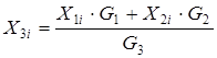 , for i=1…k [4.3]
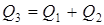 [4.4]
[4.4]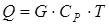 [4.5]
[4.5]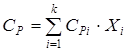 [4.6]
[4.6]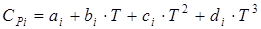 [4.7]
[4.7]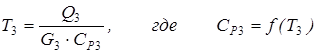 [4.8]
[4.8]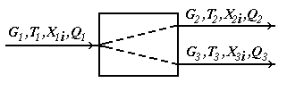
 [4.9]
[4.9] , for i=1…k [4.10]
 [4.14]
 [4.15]
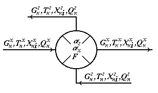
 [4.16]
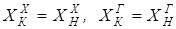 [4.17]
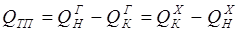 [4.18]
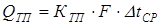 [4.19]
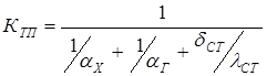 [4.20]
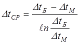 [4.21]