Заглавная страница Избранные статьи Случайная статья Познавательные статьи Новые добавления Обратная связь FAQ Написать работу КАТЕГОРИИ: ТОП 10 на сайте Приготовление дезинфицирующих растворов различной концентрацииТехника нижней прямой подачи мяча. Франко-прусская война (причины и последствия) Организация работы процедурного кабинета Смысловое и механическое запоминание, их место и роль в усвоении знаний Коммуникативные барьеры и пути их преодоления Обработка изделий медицинского назначения многократного применения Образцы текста публицистического стиля Четыре типа изменения баланса Задачи с ответами для Всероссийской олимпиады по праву 
Мы поможем в написании ваших работ! ЗНАЕТЕ ЛИ ВЫ?
Влияние общества на человека
Приготовление дезинфицирующих растворов различной концентрации Практические работы по географии для 6 класса Организация работы процедурного кабинета Изменения в неживой природе осенью Уборка процедурного кабинета Сольфеджио. Все правила по сольфеджио Балочные системы. Определение реакций опор и моментов защемления |
VHF omnidirectional range (VOR).Содержание книги
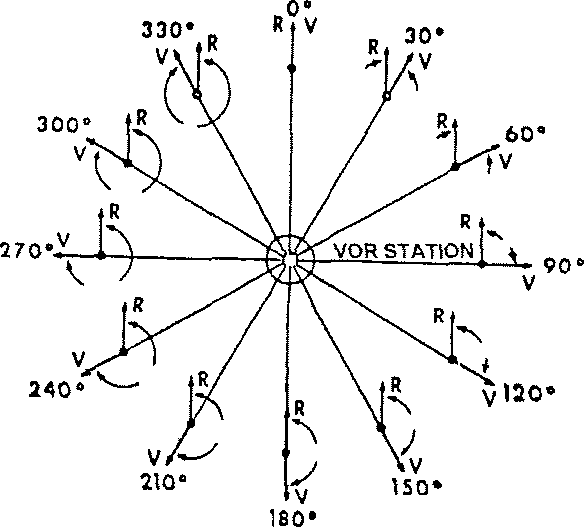
Поиск на нашем сайте The VOR system is a navigation aid that enables the flight crew to determine aircraft bearing to a VOR ground station and aircraft position with respect to, and deviation from, a selected VOR course. The VOR system operates in the frequency range between 108 to 118 MHz, with 50 kHz channel spacing. This frequency band is shared with the localiser frequencies of the Instrument Landing System (ILS), the VOR being allocated 160 of the 200 available channels. Of the 160 channels, 120 are allocated for use with VOR stations used for en route navigation. Such stations have channels in the frequency band 112 to 118 MHz and have power output of about 200W providing service ranges up to 200 nautical miles. The remaining 40 channels are allocated to terminal VOR (TVOR) stations which share the frequency band 108 - 112 MHz with the ILS localiser. TVOR stations, being terminal aids, have a power output of about 50W providing service ranges up to 25 nautical miles. Between 108.00 and 112.00 MHz VOR uses even decimal frequencies, and ILS the odd decimal frequencies. Principles of VOR The principle of VOR navigation is a phase comparison of two 30 Hz audio signals transmitted from the VOR ground station. The phase difference between the reference signal and the variable signal, measured in degrees, corresponds to the bearing of the aircraft with respect to magnetic north. The reference 30 Hz signal is transmitted on a 9960 Hz subcarrier. The sub- carrier is frequency modulated between 10,440 Hz and 9,480 Hz at a rate of 30 Hz. The variable 30 Hz signal is transmitted as amplitude modulation of the RF carrier. The 30 Hz variable signal is obtained by transferring the RF carrier to a dipole aerial and rotating the aerial at a rate of 30 revolutions per second. The field strength pattern is a Cardioid that is rotated through 360° at a rate of 1800 revolutions per minute. The phase of the 30 Hz variable signal with respect to the 30 Hz reference signal varies directly with the bearing of the receiver from the VOR station. NORTH
Fig. 12.8 REFERENCE & VARIABLE SIGNALS AROUND A VOR BEACON
The transmission from a conventional VOR (CVOR) is a horizontally polarised signal, consisting of the reference and variable phase signals and a 1020 Hz station identification signal keyed in Morse code. A summary of the VOR transmitted signals is given below: 1. Omni directional AM Signals. a) VOR reference - 30 Hz reference signal which frequency modulates the 9960 Hz ± 480 Hz. b) Keyed 1020 Hz identity tone. c) Voice audio (if used). 2. Directional Signal a) 30 Hz variable signal, which has apparent modulation of 30 Hz AM due to the rotation of the radiation pattern at 30 revolutions per second. VOR Beacon The heart of the VOR beacon lies in the aerial system. A typical aerial consists of four radiators less than a quarter-wavelength long arranged in a square to form an Alford loop. At any one instant, the currents in all the radiators are equal and alternately move clockwise and anticlockwise. The result is a doughnut shaped field with zero radiation in the upwards and downwards directions.
Fig. 12.9 THE ALFORD LOOP
A fifth loop was originally used to radiate the omni directional signal, but it was soon realised that by proper phasing the four loops could radiate an omni directional signal by themselves. The omni directional signal consists of a continuous wave which carries the Morse code ident 1020 Hz tone. Present at all times is the other 9960 Hz tone varied + 480 Hz, sinusoidally, at a rate of 30 Hz. Figure 13 shows a simplified VOR arrangement. The transmitter is crystal controlled, with a power output of 200W for CVOR and SOW for TVOR. It is amplitude modulated to a depth of 30% by the output of a mechanically driven tone wheel, which has 332 teeth and is driven by an 1800 rpm motor. The teeth are arranged in a slightly staggered manner and this irregularity imparts a cyclic variation of between 9480 Hz and 10,440 Hz on the output frequency. On the same shaft is a capacitive goniometer, fed by the same transmitter via a modulation eliminator that strips off the amplitude modulation from a portion of the transmitter output signal to provide the unmodulated RF power for the variable phase signal. The goniometer feeds the unmodulated transmitter power first to the northwest - southeast pair of Alford loops and then, 90° later, to the northeast - southwest pair of loops, generating a rotating cardioid, when combined with the modulated energy applied simultaneously to all loops. Each pair of loops is fed via a balanced bridge network. Each bridge has three arms that are each one-quarter wavelength long, the fourth arm being half a wavelength longer. Energy fed into one corner of the bridge does not appear at the diagonally opposite corner. The bridge therefore allows the mixing of two signals and application of the result to two loads without the loads affecting each other and without the signal sources affecting each other. The phasing between the tone wheel and goniometer and the physical placement of the Alford loops are such that the two 30 Hz signals are exactly in phase when viewed from magnetic north.
Fig. 12.10 VOR BEACON
VOR Receiver The airborne equipment is comprised of a horizontally polarised receiving aerial and a receiver. The receiver detects the 30 Hz amplitude modulation produced by the rotating pattern and compares it with the 30 Hz frequency modulated reference. A basic receiver is shown in figure 12.11.
BEARING
Fig. 12.11 VOR RECEIVER At the output of the receiver is an AM detector, the output of which comprises: - 30 Hz tone produced by the rotating cardioid. - 9960 Hz tone, frequency modulated ± 480 Hz by the 30 Hz reference tone. - Morse code 1020 Hz ident tone. - Voice audio, if used at the transmitter. The 30 Hz information is filtered to remove the other components and fed to the phase comparator. The 9960 Hz is filtered and limited before being applied to a frequency modulation detector, the output of which is the 30 Hz reference frequency. After filtering this is compared with the variable phase to derive the bearing information. Two types of display of VOR information are common, the first of which is called a Radio Magnetic Indicator (RMI) and indicates directly relative bearing between the aircraft and the VOR station. The RMI frequently has two indicating pointers which may be operated in conjunction with two VOR, two radio compass receivers or one of each. The second method of display uses the vertical pointer of an ILS meter. This operates in conjunction with a digital phase shifter on which any bearing may be present. The ILS meter then indicates deviation from the pre-set bearing, allowing a VOR radial to be flown using a "fly left/fly right" indication. The meter sensitivity is normally ±10° for full scale deflection (fsd). Omni-Bearing Selection The phase difference between the reference phase and the variable phase at the receiver depends on the bearing of the receiver from the beacon, referenced to magnetic north. A bearing to a beacon is expressed in whole degrees, and therefore there are a possible 360 bearing angles to a beacon, known as Radials, tUK)
Fig. 12.12 VOR RADIALS
The pilot may select any one of these radials manually by simply rotating the omni-bearing selector knob or course selector knob, as fitted to the associated indicator, which dials up the chosen bearing radial.
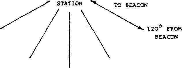
Fig. 12.13 "TO - FROM" VOR RADIALS
Every bearing has a reciprocal and therefore for any particular radial selection, there will be a second radial on the opposite side of the transmitter having the same bearing angle. The only difference between the two is one is "TO" the beacon and the other "FROM " the beacon. Figure 12.13 shows that each radial has two directions, and that each direction appears on two radials, one "TO" and the other "FROM" the station. Having selected the radial to fly, the manual VOR receiver will inform the pilot of any deviation from the selected radial and whether flying "TO" or "FROM" the beacon. Consider an aircraft bearing 250° magnetic from a VOR beacon when a course of 060° is selected. The manual VOR receiver will present an output on the associated indicator to indicate that the aircraft is left of its selected course and therefore should fly right to capture the 060° radial "TO" the beacon. n (m)
Fig. 12.14 FLYING THE VOR RADIAL
Manual VOR Receiver A typical manual VOR receiver capable of supplying a suitable indicator with deviation from a selected radial, "TO" and "FROM" indications and also a warning flag indication which comes into view when incoming signals are lost or weak, is shown. The signals are received by a common VOR/ILS localiser aerial and are processed through a normal VHF communication type of receiver up to the detector stage.
Fig. 12.15 MANUAL VOR RECEIVER
After detection, the three amplitude modulations are separated by filters. The three modulations are: (a) 30 Hz variable phase signal. (b) 9960 Hz subcarrier, frequency modulated by a 30 Hz reference phase with a deviation of + 480 Hz. (c) 1020 Hz Morse code ident signal. The 30 Hz variable phase signal is amplified and fed as an input to a phase comparator circuit for phase comparison with the reference phase signal. The 9960 Hz subcarrier is filtered to an FM detector strip consisting of amplifiers, limiters and a discriminator for removal of the 30 Hz reference phase. The 30 Hz signal is then passed to the rotor of a resolver synchro located in the indicator and operates as a phase shift device. The phase of the reference signal can therefore be varied by rotating the resolver synchro's rotor, which is connected directly to the OBS knob. A clockwise rotation of the OBS knob through X degrees causes the phase of the reference phase signal to be phase retarded by X degrees. This shifting of the reference phase gives rise to the term "Shifted Reference Phase" where the shift is the angle of the selected course radial. The 1020 Hz ident is passed into the audio integrating system and to the ASP's. It can be seen from figure 18 that the output of the phase shift resolver is further advanced by a fixed 90°. This is done to make the phase comparison easier. Phase comparators respond to slight phase variations between signals better when the signals are at 90° to each other. After the phase shift resolver the reference phase signal, which is still at 30 Hz, is amplified and applied to the phase comparator for phase comparison with the variable phase signal. The output of the phase comparator is the difference between two positive, or negative, dc voltages for operation of the deviation indicator. The sum of the same dc voltages is for the operation of the failure warning flag. The left or right deviation of the deviation bar is determined by the phase relationship of the variable phase and the shifted reference phase at the phase comparator input, such that when the inputs are in~phase quadrature the deviation bar is centred indicating an on-course situation. When the variable phase and the shifted reference phase are less than 90° out of phase, the deviation bar deflects to the right, advising the pilot to fly right. When the signals are more than 90° out of phase, the bar deflects to the left, indicating fly left to capture the selected radial. The "TO" - "FROM" indication flag is dependent upon the dc difference output from the comparator. The inputs to the "TO" - "FROM" comparator are the variable phase and the shifted reference phase advanced by a total of 180°. Omnirange Indicator Several types of indicators are used to display manual VOR information. A typical indicator is shown in figure 12.16. This type of indicator is also used for ILS approach for which the horizontal pointer, as well as the vertical pointer is used. The vertical pointer is used for omnirange and indicates by position, left or right, on which side of the selected course the aircraft is located. When in the centre it indicates an on-course heading. The number at the top of the meter is the course heading to or from the station in degrees from north. Any course can be selected by the course selector knob.
ALARM COURSE VERTICAL INDICATOR INDICATOR POINTER
Fig. 12.16 OMNIRANGE RECEIVING INDICATOR
The rotatable pointer indicates the angular difference between the selected course and the magnetic heading of the aircraft. A difference in these readings indicates that a cross wind is causing the aircraft to "crab" to stay on course. The "TO" indication will change to "FROM" when the station has been passed, and the signal is being received from the reverse direction. The "OFF" indication, over the vertical pointer, is an alarm. The appearance of this indication, which is not normally visible, indicates that some part of the system is malfunctioning and that the meter indications are unreliable. The movements of both deviation bar and "TO" - "FROM" flag are those of a centre zero micrommeter and will therefore give a central reading when the terminal supplies, from the comparator, are equal in value and polarity. A difference in supply polarity sufficient to cause 150 ji A to flow through the movement will cause full scale deflection. For the deviation bar, in VOR mode, this will occur when the aircraft is 10° off the selected radial. The "OFF" warning flag is a simple dc micrommeter arranged so that a current of 125 fiA will begin to lift the flag out of view, while 250 will take it to full scale deflection and totally out of view. The dc voltage applied to the warning flag is the sum of the dc voltage applied to the terminals of the deviation bar movement as shown.
Auto VOR Bearing The auto VOR receiver processes the received VOR signals and provides a continuous indication of magnetic bearing of the station from the aircraft. Since the raw output of the auto VOR is magnetic bearing information, the aircraft heading has no effect on the indicated magnetic bearing. The basic auto VOR magnetic bearing indicator is called the Omni Bearing Indicator (OBI). But this is rarely used these days, since the output is generally combined with compass information in a differential synchro transmitter for display on an RMI. Auto VOR Receiver Auto VOR indicates the bearing of the beacon from the aircraft receiver. In manual VOR the phase difference between the variable phase and the reference phase is the bearing of the receiver from the beacon. Due to this difference auto VOR uses the reciprocal of the reference phase, (~R0 in figure 21). The 30 Hz -R0 is extracted from the 9960 Hz sub carrier at the FM detector strip consisting of amplifiers, limiters and a discriminator. It is then applied to the rotor of a phase shift resolver and the output is again advanced by 90° to give -SR0 +90°. The 90° phase advance is to facilitate phase comparison and the S indicates that the reciprocal of the reference signal, -R0, has undergone a shift in the resolver synchro.
The 30 Hz -SR0 +90° output of the auto VOR phase shift resolver after amplification is phase compared with the 30 Hz V0 in the auto VOR phase comparator. The output of the phase comparator is the difference in two positive or negative dc voltages, which is used to control the output of a chopper circuit. The chopper is triggered by 400 Hz from the aircraft supply and its output phase is determined by the resulting polarity of the dc input, such that when the input dc difference is zero, the chopper output is zero. With two opposite polarity inputs the output is an antiphase 400 Hz signal. The 400 Hz output signal from the chopper is applied as the control phase to the two phase induction motor. The fixed phase is supplied from the aircraft 400 Hz supply, which is phase shifted ± 90° for rotation to be possible. The induction motor will turn the direction determined by the phase of the controlling signal from the chopper, and in so doing will turn the pointer of the RMI and the rotor of the resolver synchro. As the rotor of the resolver synchro rotates, the -R0 is shifted until the -SR0 +90° is in-phase quadrature with the variable phase, V0. When this occurs, the difference in the comparator dc outputs is zero, as will be the chopper output, and the motor stops. At this point, the needle of the RMI will be indicating the magnetic bearing of the VOR beacon. Radio Magnetic Indicator (RMI) The RMI has a rotatable dial face which indicates the direction of flight relative to magnetic north, and a pointer that indicates the bearing of the station being received. The pointer indicates the bearing on the dial face so that it can be compared, at a glance, with aircraft heading. Modern RMI have two pointers which may be switched to read either ADF or VOR bearings.
Fig. 12.19 RADIO MAGNETIC INDICATOR
VOR Aerial The VOR aerial is designed to receive very high frequency horizontally polarised radio signals between the frequencies of 108 and 118 MHz. VOR shares its frequency range with the localiser of the instrument landing system, and these shares the aerial system and much of the receiver unit. A typical VOR/LOC aerial, as fitted to a B737, is shown in figure 12.20. The aerial is a dual element aerial with a characteristic impedance of 50 ohms. It is composed of two balanced loops enclosed in a fibreglass housing with metallic fin tips on the leading and trailing edges and the whole assembly is located on top of the fin. VHF Nav Control Panel
/ TUNING STUB
CONNECTORS
Fig. 12.20 B737VOR/LOC AERIAL
Fig. 12.21 TYPICAL VHF NAV CONTROL PANEL
The frequency selector is used to select a frequency in the range of 108 to 118 MHz which is displayed on a frequency indicator above the frequency selector knob. Only VOR-LOC frequencies are displayed. The DME frequencies are paired with the VOR frequencies and are automatically selected with VOR frequencies. When a localiser frequency is selected, the paired glideslope frequency is automatically selected. The frequency selector knob provides a selector control logic 2-out-of-5 binary wire code which corresponds to the selected frequency, and is used to tune the RF input circuits in the receiver. Conventional VOR Errors With conventional VOR (CVOR) equipments the major bearing errors are attributable to siting of the transmitting beacon and ground station error. The major cause of error in CVOR is multipath reception. Signals arriving at the receiver may include some which arrive after reflection from objects, both natural and man-made, located in the area of the beacon. On less than ideal sites bearing errors due to multipath reception may be as high as 15° in some sectors. The ground station error results from failure of the 30 Hz reference phase and the 30 Hz variable phase to be exactly in-phase on the beacon's north bearing alignment. The major cause of this error is the spurious vertically polarised signals generated by the aerials resulting in a vertically polarised 30 Hz bearing dependent component. This 30 Hz signal is not in-phase with the 30 Hz variable phase horizontally polarised signal. The horizontally polarised aircraft aerial will pick up some of the vertically polarised signal, when the aircraft banks, so the receiver operates on a combination of the desired horizontal signal and the unwanted spurious vertically polarised signal. To overcome these problems, Doppler VOR (DVOR) was developed. Doppler VOR (DVOR) The DVOR ground beacon consists of a central omni-directional aerial surrounded by a circle of 52 aerials 44 feet in diameter. Aerials are usually Alford loops and are mounted above a large metallic mesh counterpoise. The central aerial radiates an omni-directional continuous wave that is amplitude modulated at 30 Hz, this forms the reference phase. The circle of 52 aerials is fed by a capacitive commutator or solid state switching device to simulate the rotation of a single aerial at a radius of 22 feet. Rotation is at 30 revolutions per second, and a carrier frequency 9960 Hz higher than that in the central aerial, is fed to the commutator. This 9960 Hz higher frequency is frequency modulated by the simulated rotation of the aerial, increasing in frequency as the aerial appears to move towards the receiver and decreasing in frequency as it recedes from the receiver. This forms the variable phase.
Fig. 12.22 PRINCIPLE OF DVOR
The dimensions of the outer ring of aerials are critical. A diameter of 44 feet combined with a rotational speed of 30 revolutions per second gives a radial velocity in the order of 4150 feet per second. This causes a maximum Doppler shift of 480 Hz, as required by the specification for the VOR system. The 9960 Hz frequency difference is therefore varied by ± 480 Hz at 30 Hz rate with the phase dependent on the bearing of the aircraft. In the receiver, the output of the amplitude modulation detector contains all the signals present with the conventional VOR. Phase comparison between the two 30 Hz sine waves is performed as before, the only difference being that the 30 Hz amplitude modulated signal is the reference and the 30 Hz frequency modulated signal is the variable. To maintain the same phase relationships which exist in conventional equipment, the signal is radiated anti-clockwise around the aerial system. Fig. 12.23 DOUBLE SIDED SIDEBAND DVOR
Some receivers react unfavourably to operation with a single sideband reference signal, and in consequence modern DVOR are designed to radiate double sideband transmissions. This is achieved by providing separate transmitters for each sideband (fc + 9960 and fc - 9960) and applying their transmissions to diagonally opposite aerials. The central aerial radiates the carrier frequency fc, one of the rotating aerials radiates fc + fs and the other fc - fs, where fs is the frequency of the sub- carrier. The importance of DVOR lies in the improvement it provides without any change being made to the airborne equipment. Even on bad sites DVOR can be as much as ten times better in accuracy than CVOR.
Радиосистемы посадки. Принцип действия равносигнальных РСП. Рассмотрим в качестве примера канал глиссады такой системы (рис. 12.8). Глиссадный радиомаяк ГРМ устанавливается рядом с ВПП, напротив точки приземления ЛА. Антенны ГРМ формируют в вертикальной плоскости диаграммы направленности
где Амплитуда напряженности суммарного поля в точке приема
Рис. 12.24. Диаграммы направленности антенн ГРМ и спектры излучаемых сигналов (а), спектры сигналов в точках 1, 2 и 3 (б) и структурная схема бортовой аппаратуры (в)
Коэффициенты при
Информативным параметром принимаемого сигнала является разность глубин модуляции РГМ:
Положение ЛА на линии глиссады соответствует РГМ = 0. При отклонении ЛА вверх от линии глиссады Бортовой приемник ЛА реализует алгоритм (12.11). Для формирования сигналов, пропорциональных Структурная схема канала курса с равносигнальным КРМ показана на рис.12.25.
Рис.12.25. Структурная схема канала курса с равносигнальным радиомаяком; а – структурная схема радиомаяка, диаграммы направленности, формы сигналов в бортовом ПРМ. б – структурная схема бортового изделия.
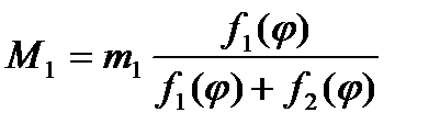
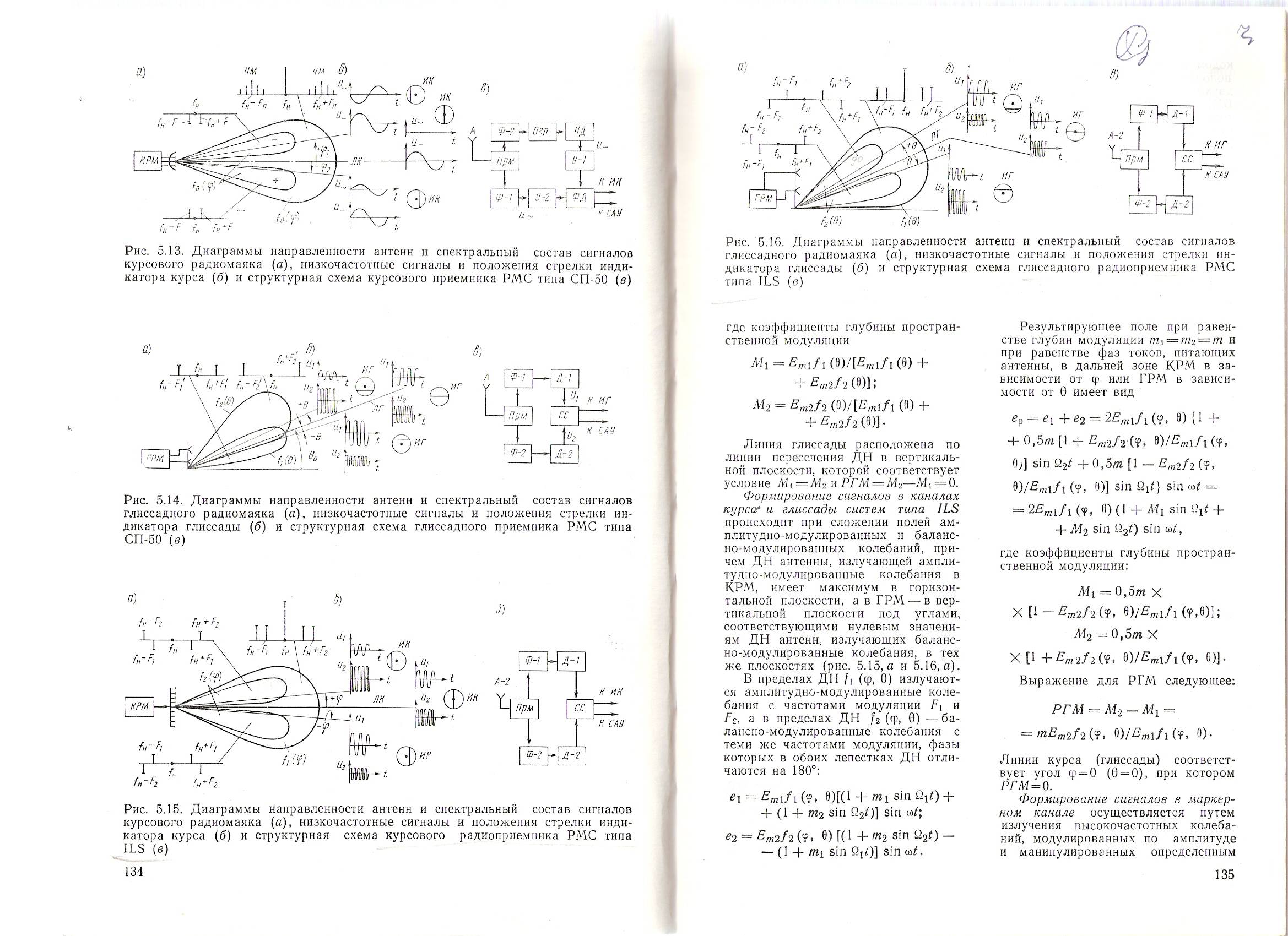
Антенны КРМ питаются синфазно амплитудно-модулированными колебаниями с частотами модуляции Ω1 и Ω2. Модулирующие колебания вырабатываются генераторами Г1 и Г2, усиливаются усилителями (У1 и У2) и поступают на модуляторы M1 и М2. На модуляторы подаются также высокочастотные колебания от задающего генератора ЗГ, предварительно усиленные усилителем мощности УМ. Напряженности полей первой и второй антенн равны
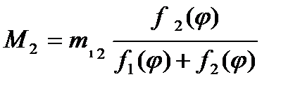
где Em1,2 - амплитуды напряженностей полей первой и второй антенн в максимумах диаграммы направленности; f1,2(φ) - нормированные диаграммы направленности в горизонтальной плоскости; m1,2 — коэффициенты модуляции на частотах Ω1 и Ω2.
Результирующее поле представляется как сумма полей несущей частоты и двух полей, соответствующих боковым частотам модуляции. Коэффициенты, определяющие зависимость глубины модуляции результирующего поля от углового параметра, определяем по выражению:
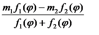
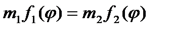
Полученные коэффициенты называются коэффициентами глубины пространственной модуляции. Линии курса соответствует направление φ0, при котором выполняется условие М1(φ0) = М2(φ0) В курсовом приемнике КРП установленном на ВС на выходе детектора выделяют с помощью фильтров Ф1 и Ф2 напряжения uc1 и uc2 амплитуды которых пропорциональны соответственно M1 и М2. Напряжения uc1 и uc2 выпрямляют и сравнивают в схеме сравнения СС. Напряжение, подаваемое на индикаторный прибор, равно разности выпрямленных напряжений, а следовательно, пропорционально разности напряжений uc1 и uc2. Если самолет находится на линии курса, то uc1 = uc2 и стрелка прибора находится в нулевом положении. При оценке изменений сигналов иc1 и иc2 используют специальный параметр - разность глубин модуляции (РГМ). Поскольку uc1 и uc2 пропорциональны M1 и М2, то отклонение стрелки индикатора курса на самолете Δк равно:
где k1 и k2 — коэффициенты пропорциональности. Таким образом, отклонение стрелки индикатора курса пропорционально РГМ. В равносигнальном курсовом радиомаяке выражение для РГМ имеет вид
РГМ= На линии курса
Точность равносигнальных РСП. При
Переходя к погрешностям измерения РГМ и определения угла
где Из (12.13) следует, что для повышения точности равносигнальной РСП необходимо увеличивать Одним из основных факторов, снижающих точность РСП, является влияние сигналов, отраженных от близких к ВПП объектов. Радиотехнические системы посадки, реализующие равносигнальный метод, характеризуются максимальной погрешностью (3 Равносигнальным РСП, кроме подверженности влиянию отраженных сигналов, свойственны и другие недостатки. Один из них – постоянство номинального угла глиссады
В курсовом радиомаяке с «опорным нулем» линия курса образуется двумя диаграммами антенной системы маяка. Рассмотрим данный вариант, где на КРМ от модуляторов на специальное устройство — фазирующий мост ФМ (рис. 12.26, а) — подают два модулированных колебания. Одно из них — обычное амплитудно-модулированное колебание с частотами модуляции Ω1 и Ω2, а второе — балансно -модулированное, боковые составляющие ω±Ω2 которого сдвинуты по фазе на 180° относительно составляющих ω±Ω1. Фазирующий мост обеспечивает синфазное питание облучателей О1 и О2 параболической антенной системы амплитудно-модулированными колебаниями и противофазное питание балансно-модулированными колебаниями. При синфазном питании облучатели О1 и О2 формируют диаграмму направленности 1, а при противофазном — диаграмму направленности 2 (см. рис.12.26, б). Результирующие диаграммы 3и 4показаны на том же рисунке. Обозначения ± 90 (± 150 ) соответствуют сдвигам по фазе на 180° составляющих поля с частотами модуляции F1 и F2. Сигнал, излучаемый в диаграмме направленности 1, может быть представлен как сумма двух амплитудно-модулированных колебаний с частотами модуляций Ω1 и Ω2:
В связи с этим диаграмму направленности 1 называют суммарной. В диаграмме направленности 2 излучается сигнал, который можно представить как разность двух амплитудно-модулированных колебаний При этом диаграмму 2 называют разностной диаграммой. Результирующая диаграмма излучения равна сумме суммарной и разностной диаграмм. Амплитуду результирующего поля с частотой модуляции F1=90 Гц определяют из полученных выражений
Рис.12.26. Схема курсового радиомаяка с «опорным нулем» (а) и диаграммы направленности антенной системы радиомаяка в горизонтальной плоскости (б)
Рис.12.27. Упрощенная функциональная схема курсового радиомаяка с «опорным нулем»
Амплитуда результирующего поля с частотой модуляции F2=150 Гц:
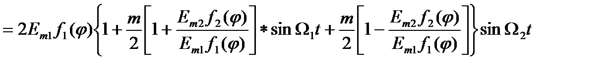
При одинаковой глубине модуляции в каналах модуляторов КРМ, т. е. при m1 = m 2 = m, амплитуда результирующего поля
Ер (φ) = E1 (φ) + E2 (φ) =
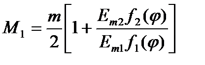
Согласно данного выражения видно, что коэффициенты в квадратных скобках при sin Ω1 t и sin Ω2 t определяют зависимость амплитуд частот модуляции от угла φ, т. е. глубину пространственной модуляции. Примем
Отклонения стрелки индикатора курса на самолете Δк пропорциональны разности глубин модуляции РГМ = (М1 – М2) = Нулевое положение стрелки индикатора курса соответствует такому углу φ0, при котором М1 = М2, т.е. РГМ = 0. Мы видим, что бортовое оборудование, которое обеспечивает работу канала курса при равносигнальном КРМ, обеспечит также работу при курсовом радиомаяке с «опорным нулем». Структурная схема одного из вариантов курсового радиомаяка с «опорным нулем» приведена на рис. 12.27. Высокочастотные колебания с передатчика ПРД поступают на разделительный мост РМ1, который необходим для исключения реакции цепей нагрузки на передатчик, а следовательно, и для предотвращения перекрестной модуляции в передатчике (кросмодуляции). Аналогичным целям служит и разделительный мост РМ2, с которого высокочастотные колебания подаются на балансные модуляторы БМ-90 и БМ-150, где они модулируются соответственно частотами 90 и 150 Гц. Полученные балансно-модулированные колебания суммируются в смесительном мосту СМ2 и питают боковые антенны (боковые облучатели О1 и ОЗ) радиомаяка. Кроме того, балансно- модулированные колебания поступают в смесительный мост СМ1, где к ним добавляются колебания несущей частоты с РМ1. В результате суммирования на выходе СМ1 образуется амплитудно-модулированное колебание с частотами модуляции 90 и 150 Гц, которое используется для питания центральной антенны (центрального облучателя 02) радиомаяка.
Рис.12.28 ДН антенн и спектр сигналов КРМ (а), НЧ сигналы и положение стрелки индикатора курса (б) и структурная схема КРП РМС типа ILS (в). В ГРМ с «опорным нулем» формирование глиссады аналогично формированию линии курса в курсовом радиомаяке с «опорным нулем» (см. рис. 12.29.).
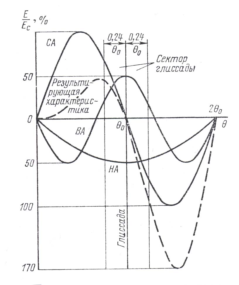
Рис.12.29. ДН антенн и спектр сигналов ГРМ (а), НЧ сигналы и положение стрелки индикатора глиссады (б) и структурная схема ГРП РМС типа ILS (в). Глиссадный радиомаяк с «опорным нулем» и компенсацией излучения под малыми углами к горизонту. Разновидностью глиссадного радиомаяка с «опорным нулем» является маяк с компенсацией излучения под малыми углами к горизонту. Такие радиомаяки позволяют уменьшить влияние переизлучателей, вызывающих, как будет показано ниже, искривление линии глиссады. С помощью дополнительной верхней антенны почти исключают влияние переизлучателей, высота которых над горизонтальной плоскостью невелика. Данная антенная система глиссадного радиомаяка с «опорным нулем» и компенсацией излучения под малыми углами к горизонту состоит из трех антенн. Соотношение амплитуд и фаз токов, питающих антенны, и коэффициенты модуляции излучаемых антеннами сигналов подбирают так, чтобы не только скомпенсировать излучение под углами порядка 1° к горизонту, но и обеспечить приемлемую линейность нарастания РГМ вблизи глиссады. Возможная диаграмма направленности рассматриваемого глиссадного радиомаяка приведена на рис. 12.30. На рис. 12.31.а показаны спектры сигналов, излучаемых нижней (НА), верхней (ВА) и средней (СА) антеннами под малыми углами к горизонту, а на рис. 12.31. б — спектр тех же сигналов, но при углах θ, близких к углу наклона глиссады θ 0.
Рис. 12.30.Диаграмма направленности по боковым частотам спектра сигнала антенной системы глиссадного радиомаяка с «опорным нулем» и с подавлением излучения под малыми углами к горизонту: СА- диаграмма средней антенны; ВА- диаграмма верхней антенны; НА – диаграмма нижней антенны:
Рис.12.31. Спектры сигналов глиссадного радиомаяка с «опорным нулем» и с подавлением излучения вблизи горизонта при малых углах к горизонту(а) и на линии глиссады (б).
Амплитуда суммарного поля всех трех антенн Ер(θ) может быть записана в виде где Ен (θ)=Еmнfн(θ); Eс (θ) = Emc fc (θ); Eв (θ) = Emв fв (θ);
Коэффициенты при sin Ω1 t и sin Ω2 t определяют зависимость глубины модуляции суммарного поля от угла Θ в вертикальной плоскости. Отклонение стрелки индикатора глиссады Δr пропорционально разности коэффициентов пространственной модуляции, т. е. РГМ = Данное выражение для РГМ является основным при анализе особенностей построения глиссадного радиомаяка с компенсацией излучения под малыми углами к горизонту.
Двухканальные посадочные радиомаяки. Эффективным способом уменьшения искривлений линии курса и глиссады, является сужение диаграмм направленности антенных систем радиомаяков. В существующих радиомаяках повышенной точности применяют антенны с диаграммами направленности шириной не более 10°. При столь узких диаграммах зоны курса и глиссады сужаются до нескольких градусов, что существенно усложняет маневр самолета по выходу на линию курса или на глиссаду. Кроме того, при больших отклонениях от траектории посадки, что наблюдается на начальном этапе захода на посадку, при малой ширине зоны становится практически невозможным определение отклонения самолета от этой траектории. Для указания направления отклонения от траектории посадки при нахождении самолета вне пределов основной диаграммы направленности радиомаяка используют дополнительные диаграммы направленности. Построенный подобным образом радиомаяк называют двухканальным. Диаграммы направленности двухканального курсового радиомаяка в горизонтальной плоскости изображены в декартовой системе координат на рис. 12.32.
Рис. 12.32. Диаграммы направленности двухканального курсового радиомаяка в горизонтальной плоскости. 1- суммарная диаграмма основного канала. 2- разностная диаграмма основного канала. 3- разностная диаграмма канала клиренса. 4 – суммарная диаграмма канала клиренса.
Как видно из диаграмм этого рисунка, двухканальный радиомаяк формирует зону курса как радиомаяк с «опорным нулем» и по существу представляет собой два радиомаяка со своими диаграммами направленности. Диаграммы f1(φ) и f 2(φ) служат для точноговывода самолета на траекторию посадки и обеспечивают работу так называемого узкого канала курса или основного канала курсового радиомаяка. Диаграммы fк1 (φ) и fк2 (φ) служат только для указания направления выхода на траекторию посадки, т. е. для указания стороны отклонения от линии курса. Эти диаграммы обеспечивают работу дополнительного широкого канала курса. Схожее построение имеют и двухканальные глиссадные радиомаяки, в которых дополнительная диаграмма обеспечивает, главным образом, индикацию положения-глиссады при полете самолета под малыми углами к горизонту. Для формирования дополнительной диаграммы направленности здесь и
|
|||||
|
|
Последнее изменение этой страницы: 2019-11-02; просмотров: 342; Нарушение авторского права страницы; Мы поможем в написании вашей работы! infopedia.su Все материалы представленные на сайте исключительно с целью ознакомления читателями и не преследуют коммерческих целей или нарушение авторских прав. Обратная связь - 216.73.216.102 (0.009 с.) |


 и
и  , точка пересечения которых соответствует заданной линии глиссады ЛГ (рис. 12.24,а), и излучают непрерывные АМ колебания, несущие частоты которых равны, а частоты модуляции составляют
  =90 Гц, а
  =150 Гц. В точке приема действует сигнал, равный сумме напряженностей полей, создаваемых антеннами ГРМ:
 ;
;  , (12.8)
 – амплитуда напряженности поля;
  – коэффициент АМ;
  и
и  .
. (12.9)
 и
и  определяют зависимость амплитуд колебаний частот модуляции от угла
  и называются коэффициентами глубины пространственной модуляции:
 ,
,  . (12.10)
 . (12.11)
 и РГМ > 0, а при полете ЛА ниже линии глиссады РГМ < 0 (рис. 12.24,б).
 и
и  , используется автоматическая регулировка усиления АРУ приемника Прм (рис. 12.24,в) по суммарному сигналу. Фильтры Ф90 и Ф150 выделяют сигналы с частотами модуляции
  и
и  . В схеме сравнения СС образуется разность этих сигналов, пропорциональная РГМ и несущая информацию об угловом отклонении
  от линии глиссады.
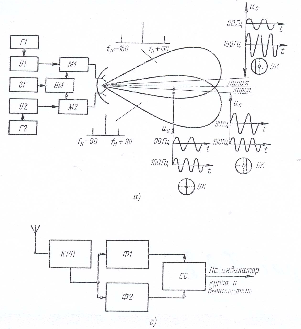

 Результирующее поле антенн курсовых радиомаяков равно сумме полей е1 и е2. В курсовых равносигнальных радиомаяках необходимое условие Еm1 = Еm2 = Еm, при этом результирующее поле

 и таким образом РГМ = 0.
  из (12.11) можно получить основное уравнение равносигнальной РСП:
 . (12.12)
 , получаем
 ;
;  , (12.13)
 – пеленгационная чувствительность.
 и
и  . Увеличение
  ограничено тем, что в суммарном сигнале
  общий коэффициент модуляции на РСН не должен превышать 1. Уменьшение
  ведет к снижению дальности действия РСП. Поэтому наиболее целесообразным средством повышения точности следует считать увеличение
  ), составляющей примерно 0,3° в канале глиссады и 0,25° в канале курса.
 – связан с применением на ГРМ неподвижных антенн. Этот недостаток не позволяет оптимизировать угол
  для ЛА с разными характеристиками. Кроме того, траектория посадки вблизи точки приземления находится в ближней зоне антенн глиссадного радиомаяка, что приводит к ненадежности информации о
  и вынуждает использовать на заключительном этапе посадки радиовысотомер как главный датчик положения ЛА в вертикальной плоскости.


 ,
,