Заглавная страница Избранные статьи Случайная статья Познавательные статьи Новые добавления Обратная связь КАТЕГОРИИ: ТОП 10 на сайте Приготовление дезинфицирующих растворов различной концентрацииТехника нижней прямой подачи мяча. Франко-прусская война (причины и последствия) Организация работы процедурного кабинета Смысловое и механическое запоминание, их место и роль в усвоении знаний Коммуникативные барьеры и пути их преодоления Обработка изделий медицинского назначения многократного применения Образцы текста публицистического стиля Четыре типа изменения баланса Задачи с ответами для Всероссийской олимпиады по праву 
Мы поможем в написании ваших работ! ЗНАЕТЕ ЛИ ВЫ?
Влияние общества на человека
Приготовление дезинфицирующих растворов различной концентрации Практические работы по географии для 6 класса Организация работы процедурного кабинета Изменения в неживой природе осенью Уборка процедурного кабинета Сольфеджио. Все правила по сольфеджио Балочные системы. Определение реакций опор и моментов защемления |
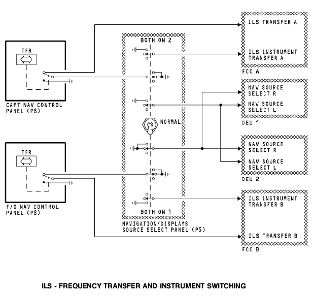
ILS - frequency transfer and instrument switching
General The frequency transfer switch on the NAV control panel and the VHF NAV transfer switch on the navigation/displays source select panel have interface with the FCCs and DEUs. Frequency Transfer Switch
The frequency transfer switch on the NAV control panel permits the crew to transfer the frequency from the standby display window on the NAV control panel, to the active display window. The transfer switch is a momentary action switch. When you push the switch, it changes the discrete level to the FCCs. The discrete tells the FCC when there is an ILS frequency change. Navigation/Displays Source Select Panel
The VHF NAV switch on the navigation/displays source select panel is a three position switch. The positions are; BOTH ON 1, NORMAL, and BOTH ON 2. This switch changes the source of the data that the DEUs use for the ILS displays. In the NORMAL position, MMR 1 supplies data for the captain displays and MMR 2 supplies data for the first officer displays. When you select BOTH ON 1, the DEUs use MMR 1 as the source for the captains displays and first officers displays. When you select BOTH ON 2, MMR 2 is the source for the captains displays and first officers displays. Discrete signals also go to the flight control computers (FCCs) to signal that the switch is not in the normal position.
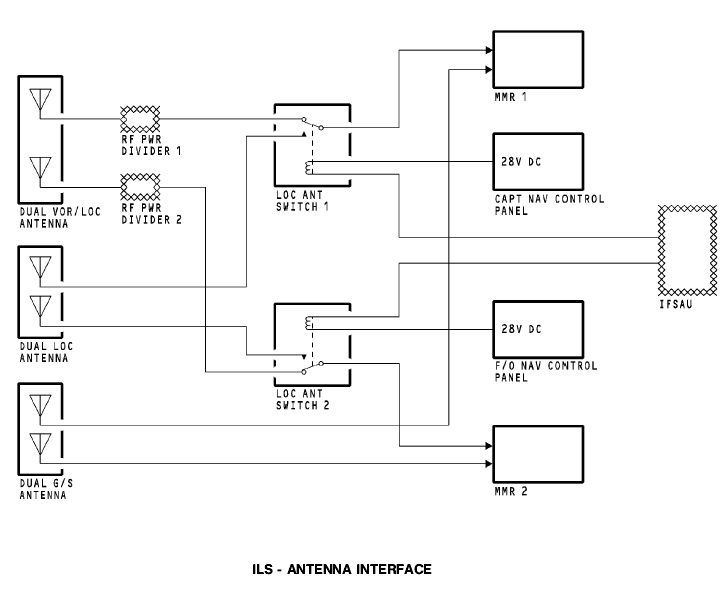
ILS - ANTENNA INTERFACE General
The multi-mode receivers (MMRs) get RF inputs from these antennas: · VOR/LOC antenna on the vertical stabilizer · Localizer antenna in the nose radome · Glideslope antenna in the nose radome.
The VOR/LOC antenna RF inputs go through the power dividers then to the localizer (LOC) antenna (ANT) switches. The localizer antenna RF inputs go directly to the LOC ANT switches. The antenna switches select the VOR/LOC antenna or localizer antenna as the source of the localizer RF signal input to the MMRs. The glideslope antenna inputs do not go through the antenna switches. Glideslope antenna RF inputs go directly to the MMRs. When you tune an ILS frequency on the navigation (NAV) control panels, they send 28v dc to the LOC antenna switches. The LOC ANT switches use 28v dc from the NAV control panels and a discrete signal from the integrated flight system accessory unit (IFSAU) for operation. The IFSAU sends the discrete when it receives a discrete from the Flight Control Computers (FCCs). The FCCs send the discrete when you select the approach (APP) or localizer (LOC) mode on the DFCS mode control panel.
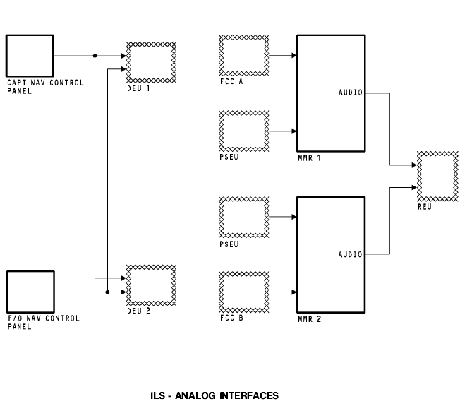
ILS - ANALOG INTERFACES General When you tune an ILS frequency on the NAV control panels, discrete signals go to the DEUs to tell if the frequency is an ILS or VOR frequency. Each NAV control panel sends the discrete signal to the DEU 1 and DEU 2. The FCCs send an ILS tune inhibit to the ILS function of the MMRs during the approach (APP) mode of operation. The ILS receiver will not accept another tune frequency during this mode. The PSEU sends air/ground discrete signals to the MMRs to set the flight leg count in the internal memory, and also inhibit test in the air. The MMRs send ILS ground station audio to the REU. The REU sends the audio to the flight compartment.
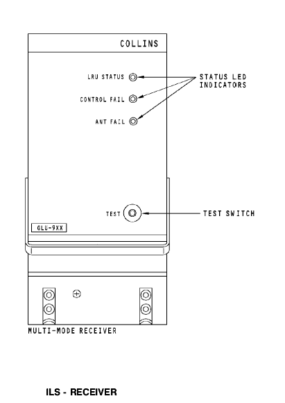
ILS - RECEIVER Purpose The multi-mode receiver contains an ILS receiver and a global positioning system (GPS) sensor unit. The ILS receiver function supplies localizer and glideslope deviation to different airplane systems. The GPS sensor unit supplies position data and time to the flight management computer system (FMCS). Description
The MMR is a standard ARINC 600 3 MCU unit with dimensions 3.75 x 7.75 x 14.6 inches. The receiver weighs 10 pounds and uses 115v ac 400 Hz power for operation. Test and Indication
There are status LED indicators and a test switch on the front of the multi mode receiver. The test switch starts a functional test of the receiver. The LED status indicators show test results.
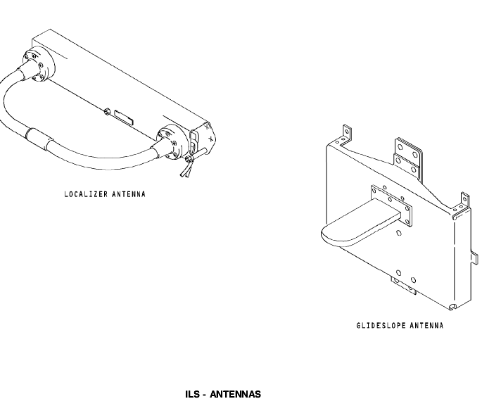
ILS - ANTENNAS Localizer Antenna The localizer antenna has two elements. One element supplies RF inputs to ILS receiver 1 and one element supplies RF inputs to ILS receiver 2. The localizer antenna receives frequencies from 108.1 Mhz to 111.95 Mhz at odd tenth intervals. Glideslope Antenna The glideslope antenna also has two elements. One element supplies RF signal inputs to MMR 1 and one element supplies RF signal inputs to MMR 2. The glideslope antenna receives frequencies from 328.6 Mhz to 335.4 Mhz.
|
|||||
|
|
Последнее изменение этой страницы: 2019-11-02; просмотров: 136; Нарушение авторского права страницы; Мы поможем в написании вашей работы! infopedia.su Все материалы представленные на сайте исключительно с целью ознакомления читателями и не преследуют коммерческих целей или нарушение авторских прав. Обратная связь - 18.219.189.247 (0.005 с.) |