Заглавная страница Избранные статьи Случайная статья Познавательные статьи Новые добавления Обратная связь FAQ Написать работу КАТЕГОРИИ: ТОП 10 на сайте Приготовление дезинфицирующих растворов различной концентрацииТехника нижней прямой подачи мяча. Франко-прусская война (причины и последствия) Организация работы процедурного кабинета Смысловое и механическое запоминание, их место и роль в усвоении знаний Коммуникативные барьеры и пути их преодоления Обработка изделий медицинского назначения многократного применения Образцы текста публицистического стиля Четыре типа изменения баланса Задачи с ответами для Всероссийской олимпиады по праву 
Мы поможем в написании ваших работ! ЗНАЕТЕ ЛИ ВЫ?
Влияние общества на человека
Приготовление дезинфицирующих растворов различной концентрации Практические работы по географии для 6 класса Организация работы процедурного кабинета Изменения в неживой природе осенью Уборка процедурного кабинета Сольфеджио. Все правила по сольфеджио Балочные системы. Определение реакций опор и моментов защемления |
Electronic Equipment CompartmentСодержание книги
Поиск на нашем сайте The multi-mode receivers (MMRs) are in the electronic equipment compartment. MMR 1 is on the E1-2 shelf. MMR 2 is on the E1-4 shelf. The LOC antenna switches are on the side of the E1 rack. Nose Radome The glideslope and localizer antennas are in the nose radome. The glideslope antenna is above the weather radar antenna. The localizer antenna is below the weather radar antenna.
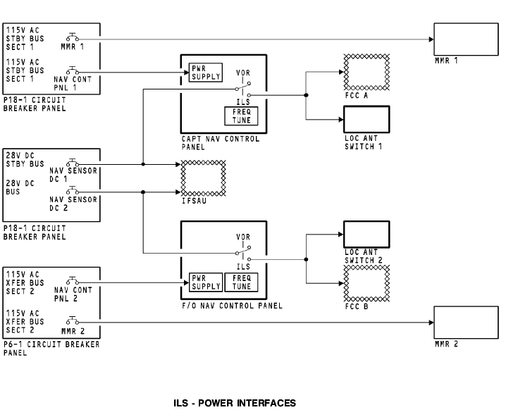
POWER INTERFACES Power Inputs The P18-1 circuit breaker panel contains the MMR 1 and NAV CONT PNL 1 circuit breakers. The circuit breakers receive 115v ac from the 115v ac standby bus section 1. The circuit breakers supply power to the multi mode receiver 1 and the captain’s NAV control panel. The P18-1 circuit breaker panel also contains the NAV SENSOR DC 1 and NAV SENSOR DC 2 circuit breakers. The circuit breakers receive 28v dc from the 28v dc standby bus and the 28v dc bus. The circuit breakers send 28v dc to the NAV control panels and to the integrated flight system accessory unit (IFSAU). For the ILS, The IFSAU contains circuits that supply a discrete signal to the LOC antenna switches for operation. The IFSAU uses the 28v dc from the NAV control panel and a discrete signal from the FCC to set the logic to send a discrete signal to operate the LOC antenna switches. The P6-1 circuit breaker panel contains the NAV CONT PNL 2 and the MMR 2 circuit breakers. The circuit breakers receive 115v ac from the 115v ac transfer bus section 2. The circuit breakers supply power to the first officer’s NAV control panel and the multi mode receiver 2. When you tune an ILS frequency on the NAV control panels, 28v dc goes to the on-side FCC and LOC antenna switch. The FCC’s use the 28v dc for mode selection. The LOC antenna switches use the 28v dc for operation.
ILS - DIGITAL INTERFACE General These are the components that have a digital interface with the multi-mode receivers: · Captain and first officer NAV control panels · Flight data acquisition unit (FDAU) · Standby attitude indicator · Ground proximity warning computer (GPWC) · Flight management computer (FMC) 1 and 2 · Display electronics units (DEU) · FCC A and FCC B.
Digital Inputs The NAV control panels supply frequency tune inputs to the multi-mode receivers. The NAV control panels also send tune inputs to the VOR and DME systems on a separate data bus. Digital Outputs Each MMR has two output data buses. Output data bus 1 goes to the FCCs. Output data bus 2 goes to many components. The FDAU receives ILS data and status of the MMR receivers. The FDAU processes the data for the flight data recorder. The standby attitude indicator uses localizer and glideslope deviations for the ILS deviation bar operation. Only MMR 1 sends ILS data to the standby attitude indicator. The GPWC receives glideslope data from both ILS receivers for mode 5 (below glideslope) warnings. FMC 1 and FMC 2 receive ILS data and receiver status from the two MMRs. The FMCS uses the ILS data for position update calculations. The FCCs use ILS data to calculate airplane steering commands for the digital flight control system (DFCS) autopilot and flight director modes. The DEU 1 receives two inputs from MMR 1 and two inputs from MMR 2. DEU 2 also receives two inputs from MMR 1 and two inputs from MMR 2. The CDS uses the ILS data to calculate the localizer deviation and glideslope deviation displays.
|
||
|
|
Последнее изменение этой страницы: 2019-11-02; просмотров: 208; Нарушение авторского права страницы; Мы поможем в написании вашей работы! infopedia.su Все материалы представленные на сайте исключительно с целью ознакомления читателями и не преследуют коммерческих целей или нарушение авторских прав. Обратная связь - 216.73.216.102 (0.006 с.) |