Заглавная страница Избранные статьи Случайная статья Познавательные статьи Новые добавления Обратная связь FAQ Написать работу КАТЕГОРИИ: ТОП 10 на сайте Приготовление дезинфицирующих растворов различной концентрацииТехника нижней прямой подачи мяча. Франко-прусская война (причины и последствия) Организация работы процедурного кабинета Смысловое и механическое запоминание, их место и роль в усвоении знаний Коммуникативные барьеры и пути их преодоления Обработка изделий медицинского назначения многократного применения Образцы текста публицистического стиля Четыре типа изменения баланса Задачи с ответами для Всероссийской олимпиады по праву 
Мы поможем в написании ваших работ! ЗНАЕТЕ ЛИ ВЫ?
Влияние общества на человека
Приготовление дезинфицирующих растворов различной концентрации Практические работы по географии для 6 класса Организация работы процедурного кабинета Изменения в неживой природе осенью Уборка процедурного кабинета Сольфеджио. Все правила по сольфеджио Балочные системы. Определение реакций опор и моментов защемления |
Англійська мова професійного спрямуванняСодержание книги
Поиск на нашем сайте
Г.О. Корсун, К.О. Галацин
АНГЛІЙСЬКА МОВА ПРОФЕСІЙНОГО СПРЯМУВАННЯ Частина 2 НАВЧАЛЬНИЙ ПОСІБНИК Рекомендовано Міністерством освіти і науки України
КИЇВ ВПК «Політехніка» УДК ББК Рекомендовано Міністерством освіти і науки України як навчальний посібник для студентів вищих навчальних закладів (Лист № від р.) Автори: Корсун Ганна Олексіївна Галацин Катерина Олександрівна Рецензенти: Бартків О.С, к.пед.н., доцент кафедри соціальної педагогіки Східноєвропейського національного університету імені Лесі Українки Мельник О.В., к.пед.н., старший науковий співробітник Інституту проблем виховання НАПН України Скуратовський А.К. к.тех.н, доцент кафедри ЛТФТ НТУУ «КПІ» Корсун Г. О., Галацин К.О. Навчальний посібник «Англійська мова професійного спрямування» для студентів третього курсу напрямів підготовки «Прикладна механіка», «Інженерна механіка», «Машинобудування» механіко-машинобудівного інституту. Частина 2: Навч. посіб. / – К.: ВПК «Політехніка», – 2013. – 150 с. ISBN Подано тексти з професійно орієнтованої тематики, а саме про види зчеплень та зубчатих передач, механізми, процеси оброблення матеріалів, системи управління, підшипники, зносостійкість інструментів. Сприятиме систематизації знань студентів з іноземної мови професійного спрямування, формуванню навичок та розвитку вмінь читання, аудіювання, говоріння, письма та перекладу, а також набуттю іншомовної професійної компетенції. Може бути використаний як під час аудиторної роботи, так і в самостійній роботі студентів. Посібник є логічним продовженням першої частини. Для студентів третього курсу таких напрямів підготовки, як 6.050501 «Прикладна механіка», 6.050502 «Інженерна механіка», 6.050503 «Машинобудування» механіко-машинобудівного інституту.
УДК ББК Передрукування заборонено © Корсун Г.О., Галацин К.О. НТУУ «КПІ» 2013
ПЕРЕДМОВА Відповідно до Загальноєвропейських рекомендацій з мовної освіти провідною ідеєю навчання іноземної мови у немовних вищих навчальних закладах виступає формування іншомовної комунікативної компетенції у майбутніх інженерів. Виходячи з цього, вивчення дисципліни «Англійська мова професійного спрямування» сприяє формуванню у студентів професійної мовної компетенції, що сприятиме їхньому ефективному функціонуванню у культурному розмаїтті навчального та професійного середовища. Метою даного навчального посібника є навчання студентів інженерних спеціальностей англійська мова професійного спрямування, а саме практичного володіння іноземною мовою в обсязі, необхідному для ведення бесіди у сферах ситуативного та професійного спілкування з метою одержання інформації. Даний посібник розрахований на досягнення рівня володіння мовою В2, який є стандартом для ступеня бакалавра і реалізує потреби студента як користувача англійської мови. Навчальний посібник укладено у двох частинах. Друга частина, яка є логічним продовженням першої частини, складається з 10 змістовних уроків відповідно до робочої навчальної програми дисципліни «Англійська мова професійного спрямування» для спеціальностей «Прикладна механіка», «Інженерна механіка», «Машинобудування», і включає вивчення таких тем, як Materials Handling, Geared Systems and Mechanisms, Tool Wear and Sharpening, Mechanical Elements, Mechanical Failure Modes тощо. Кожен урок містить англомовні оригінальні тексти з розробленим методичним забезпеченням. Навчальний посібник може використовуватись у роботі зі студентами немовних спеціальностей вищих технічних закладів освіти України. У кожному розділі підручника та в додатках подається теоретичний матеріал передбачений програмою підготовки фахівців в галузі машинобудування Навчальний посібник розроблено з метою підготовки студентів до ефективної комунікації у їхньому академічному та професійному оточенні. Посібник забезпечує формування стійких мовленнєвих навичок та вмінь, необхідних для свідомого володіння англійською мовою професійного спрямування. Він надає можливість студентам оволодіти основними видами комунікативної діяльності (аудіювання, читання, письма, говоріння). Тому передбачається, що комунікативні мовні компетенції будуть формуватись для адекватної поведінки в реальних ситуаціях академічного та професійного життя, які є загальними для студентів різних спеціальностей.
CONTENTS
UNIT 1. MATERIALS HANDLING Task 1. List factors that must be known when a material handling system is designed. Compare your list with that of your partner. This is how we express our opinion in English. Study this table.
Task 5. Read and translate the following text. Task 6. Complete the following sentences with the appropriate word or phrase from the text. 1. Jacks are _______________, hand-operated devices for moving heavy loads through short distances. 2. Hoists for coal mines are principally of the __________________ type, for operating in balance from one level. 3. The operation of hoists may be controlled manually, _________________, or semi-automatically. 4. Elevators are widely used to transport ____________________ and freight vertically or at an incline in buildings and structures. 5. Escalators have the advantages of continuity of motion, great capacity, and small amounts of space __________________ and current consumed for each passenger carried.
Task 7. Translate the following passage into Ukrainian: Chain, because of its energy absorption properties, flexibility, and ability to follow contours, is a versatile medium for lifting, towing, pulling, and securing. Chain can be divided into two main groups: welded and weldless. Welded chain is further categorized into grades by strength and used for many high-strength industrial applications, while weldless chain is used for light-duty low-strength industrial and commercial applications. The most widely used variety is hoist load wheel chain, a short link style used as the lifting chain in hand, electric, and air-powered hoists. Some roller chain is still used for this purpose, but its use is steadily declining because of the higher strength per weight ratio and three-dimensional flexibility of welded link chain. Task 15. Watch the video file “What Is Material Handling. Try to explain what is material handling? This video, produced by the Material Handling Industry of America and the Material Handling Equipment Distributors Association, which Fred Hill is a proud member of, does a great job of explaining exactly what material handling is and how it touches every industry and plays a pivotal role in day-to-day life. Task 1. What is the role of gears in modern world? What types of gear can you name? Task 4. Read and translate the text. Gear and Gearing (part 1) External spur gears are cylindrical gears with straight teeth cut parallel to the axes. Gears transmit drive between parallel shafts. Tooth loads produce no axial thrust. Excellent at moderate speeds but tend to be noisy at high speeds. Shafts rotate in opposite directions. Internal spur gears provide compact drive arrangements for transmitting motion between parallel shafts rotating in the same direction. Helical gears are cylindrical gears with teeth cut at an angle to the axes. Provides drive between shafts rotating in opposite directions, with superior load carrying capacity and quietness than spur gears. Tooth loads produce axial thrust. Crossed helical gears are helical gears that mesh together on non-parallel axes. Straight bevel gears have teeth that are radial toward the apex and are of conical form. Designed to operate on intersecting axes, bevel gears are used to connect two shafts on intersecting axes. The angle between the shafts equals the angle between the two axes of the meshing teeth. End thrust developed under load tends to separate the gears. Spiral bevel gears have curved oblique teeth that contact each other smoothly and gradually from one end of a tooth to the other. Meshing is similar to that of straight bevel gears but is smoother and quieter in use. Left hand spiral teeth incline away from the axis in an anti-clockwise direction looking on small end of pinion or face of the gear; right-hand teeth incline away from axis in clockwise direction. The hand of spiral of the pinion is always opposite to that of the gear and is used to identify the hand of the gear pair and to connect two shafts on intersecting axes as with straight bevel gears. The spiral angle does not affect the smoothness and quietness of operation or the efficiency but does affect the direction of the thrust loads created. A left-hand spiral pinion driving clockwise when viewed from the large end of the pinion creates an axial thrust that tends to move the pinion out of mesh. Zero bevel gears have curved teeth lying in the same general direction as straight bevel teeth but should be considered to be spiral bevel gears with zero spiral angles. Hypoid bevel gears are a cross between spiral bevel gears and worm gears. The axes of hypoid bevel gears are non-intersecting and non-parallel. The distance between the axes is called the offset. The offset permits higher ratios of reduction than is practicable with other bevel gears. Hypoid bevel gears have curved oblique teeth on which contact begins gradually and continues smoothly from one end of the tooth to the other. Worm gears are used to transmit motion between shafts at right angles, that do not lie in a common plane and sometimes to connect shafts at other angles. Worm gears have line tooth contact and are used for power transmission, but the higher the ratio the lower the efficiency. If a gear tooth of the involute curvature acts against the involute tooth of a mating gear while rotating at a uniform rate, the angular motion of the driven gear will also be uniform, even though the center-to-center distance is varied. The relative rate of motion between driving and driven gears having involute tooth curves is established by the diameters of their base circles. Contact between intermeshing involute teeth on a driving and driven gear is along a straight line that is tangent to the two base circles of these gears. This is the line of action. The point where the line of action intersects the common center-line of the mating involute gears, establishes the radii of the pitch circles of these gears; hence true pitch circle diameters are affected by a change in the center distance. (Pitch diameters obtained by dividing the number of teeth by the diametric pitch apply when the center distance equals the total number of teeth on both gears divided by twice the diametric pitch.) The pitch diameters of mating involute gears are directly proportional to the diameters of their respective base circles; thus, if the base circles of one mating gear is three times as large as the other, the pitch circle diameters will be in the same ratio. The angle between the line of action and a line perpendicular to the common center-line of the mating gears, is the pressure angle; hence the pressure angle is affected by any change in the center distance. When an involute curve acts against a straight line (as in the case of an involute pinion acting against straight-sided rack teeth), the straight line is tangent to the involute and perpendicular to its line of action. The pressure angle, in the case of the involute pinion acting against straight-sided rack teeth, is the angle between the line of action and the line of the rack's motion. If the involute pinion rotates at a uniform rate, movement of the rack will also be uniform. Task 5. The definitions of the terms are given. Guess these terms and put down these words into the table.
Task 6. Match the words from column A with column B. Make word combinations and translate them into Ukrainian:
Gears and Gearing A gear or more correctly a "gear wheel" is a rotating machine part having cut teeth, or cogs, which mesh with another toothed part in order to transmit torque. Two or more gears working in tandem are called a transmission and can produce a mechanical advantage through a gear ratio and thus may be considered a simple machine. Geared devices can change the speed, magnitude, and direction of a power source. The most common situation is for a gear to mesh with another gear, however a gear can also mesh a non-rotating toothed part, called a rack, thereby producing translation instead of rotation. The gears in a transmission are analogous to the wheels in a pulley. An advantage of gears is that the teeth of a gear prevent slipping. When two gears of unequal number of teeth are combined a mechanical advantage is produced, with both the rotational speeds and the torques of the two gears differing in a simple relationship. In transmissions which offer multiple gear ratios, such as bicycles and cars, the term gear, as in first gear, refers to a gear ratio rather than an actual physical gear. The term is used to describe similar devices even when gear ratio is continuous rather than discrete, or when the device does not actually contain any gears, as in a continuously variable transmission. An external gear is one with the teeth formed on the outer surface of a cylinder or cone. Conversely, an internal gear is one with the teeth formed on the inner surface of a cylinder or cone. For bevel gears, an internal gear is one with the pitch angle exceeding 90 degrees. Internal gears do not cause direction reversal. Numerous nonferrous alloys, cast irons, powder-metallurgy and plastics are used in the manufacture of gears. However steels are most commonly used because of their high strength to weight ratio and low cost. Plastic is commonly used where cost or weight is a concern. A properly designed plastic gear can replace steel in many cases because it has many desirable properties, including dirt tolerance, low speed meshing, and the ability to "skip" quite well. Manufacturers have employed plastic gears to make consumer items affordable in items like copy machines, optical storage devices, VCRs, cheap dynamos, consumer audio equipment, servo motors, and printers. Gears are most commonly produced via hobbing, but they are also shaped, broached, cast, and in the case of plastic gears, injection molded. For metal gears the teeth are usually heat treated to make them hard and more wear resistant while leaving the core soft and tough. For large gears that are prone to warp a quench press is used. Gear geometry can be inspected and verified using various methods such as industrial CT scanning, coordinate-measuring machines, white light scanner or laser scanning. Particularly useful for plastic gears, industrial CT scanning can inspect internal geometry and imperfections such as porosity. Material Removal Processes Material removal processes, which include machining, cutting, grinding, and various nonmechanical chipless processes, are desirable or even necessary for the following basic reasons: closer dimensional tolerances, surface roughness, or surface-finish characteristics may be required than are available by casting, forming, powder metallurgy, and other shaping processes; and part geometries may be too complex or too expensive to be manufactured by other processes. However, material removal processes inevitably waste material in the form of chips, production rates may be low, and unless carried out properly, the processes can have detrimental effects on the surface properties and performance of parts. Traditional material removal processes consist of turning, boring, drilling, reaming, threading, milling, shaping, planing, and broaching, as well as abrasive processes such as grinding, ultrasonic machining, lapping, and honing. A factor of great significance in metal cutting is tool wear. Many factors determine the type and rate at which wear occurs on the tool. The major critical variables that affect wear are tool temperature, type and hardness of tool material, grade and condition of workpiece, abrasiveness of the microconstituents in the workpiece material, tool geometry, feed speed, and cutting fluid. The type of wear pattern that develops depends on the relative role of these variables. Tool wear can be classified as flank wear; crater wear on the tool face; localized wear, such as the rounding of the cutting edge; chipping or thermal softening and plastic flow of the cutting edge; concentrated wear resulting in a deep groove at the edge of a turning tool, known as wear notch. The general types of machine tools are lathes; turret lathes; screw, boring, drilling, reaming, threading, milling, and gear-cutting machines; planers and shapers; broaching, cutting-off, grinding, and polishing machines. Each of these is subdivided into many types and sizes. Turning is a machining operation for all types of metallic and nonmetallic materials and is capable of producing circular parts with straight or various profiles. The cutting tools may be single-point or form tools. The most common machine tool used is a lathe; modern lathes are computer-controlled and can achieve high production rates with little labor. Boring is a machining process for producing internal straight cylindrical surfaces or profiles, with process characteristics and tooling similar to those for turning operations. Boring machines are of two general types, horizontal and vertical, and are frequently referred to as horizontal boring machines and vertical boring and turning mills. A classification of boring machines comprises horizontal boring, drilling, and milling machines; vertical boring and turning mills; vertical multispindle cylinder boring mills; vertical cylinder boring mills; vertical turret boring mills; car-wheel boring mills; diamond or precision boring machines; and jig borers. Drilling is a commonly employed hole-making process that uses a drill as a cutting tool for producing round holes of various sizes and depths. Drilled holes may be subjected to additional operations for better surface finish and dimensional accuracy, such as reaming and honing. Drilling machines are intended for drilling holes, tapping, counter boring, reaming, and general boring operations. They may be classified into a large variety of types: twist drills, straight-shank twist drills, taper-shank drills, heavy-duty drill, and radial drill. A reaming is a multiple-cutting edge tool used to enlarge or finish holes, and to provide accurate dimensions as well as good finish. Reamers are of two types: 1)rose and 2) fluted. The rose reamer is a heavy-bodied tool with end cutting edges. It is used to remove considerable metal and to true up a hole preparatory to flute reaming. It is similar to the three- and four-fluted drills. Wide cylindrical lands are provided back of the flute edges. Threads may be formed on the outside or inside of a cylinder or cone with single-point threading tools, with threading chasers, with taps, with dies, by thread milling, by thread rolling, and by grinding. There are numerous types of taps, such as hand, machine screw, pipe, and combined pipe tap and drill. Small taps usually have no radial relief. Large taps may have still more flutes. Milling is one of the most versatile machining processes and is capable of producing a variety of shapes involving flat surfaces, slots, and contours (Fig. 1)
Fig. 1 Basic types of milling cutters and operations. (a) Slab (peripheral) milling; (b) face milling; (c) end milling. Task 5. Ask your groupmate about the objects in the picture below. Translate the terms and describe the differences between these types of drills. If you have problems contact the dictionary or any Internet resources.
Cutting options 1) _______: abrasive cutting, removing a kerf of material. Includes cutting with toothed blades and abrasive wheels. 2) _______: use of pressure on smooth-edged blades for guillotining and punching. 3) _______: removal of material across the full diameter of a hole, or using hole-saws for cutting circumferential kerfs. 4) _______: removal of surface layers with multiple cutting wheel passes. 5) _______: using oxy fuel (oxygen + combustible gas, often acetylene)
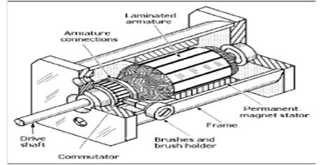
Task 16. Watch the video file “Tools with Integrated Dampening” about pioneering solution to vibration problems when machining with long slender tools. Write a short report (100-120 words) on a process that is shown. Task 3. Describe the main operation principle of a fractional horsepower permanent-magnet DC servomotor that is shown and get ready for presenting your report at the conference “Innovations in Science and Technology”. Write a plan of your report.
TOOL WEAR Metal cutting tools wear constantly when they are being used. A normal amount of wear should not be a cause for concern until the size of the worn region has reached the point where the tool should be replaced. Normal wear cannot be avoided and should be differentiated from abnormal tool breakage or excessively fast wear. Tool breakage and an excessive rate of wear indicate that the tool is not operating correctly and steps should be taken to correct this situation. There are several basic mechanisms that cause tool wear. It is generally understood that tools wear as a result of abrasion which is caused by hard particles of work material plowing over the surface of the tool. Wear is also caused by diffusion or alloying between the work material and the tool material. In regions where the conditions of contact are favorable, the work material reacts with the tool material causing an attrition of the tool material. The rate of this attrition is dependent upon the temperature in the region of contact and the reactivity of the tool and the work materials with each other. Diffusion or alloying also occurs where particles of the work material are welded to the surface of the tool. These welded deposits are often quite visible in the form of a built-up edge, as particles or a layer of work material inside a crater or as small mounds attached to the face of the tool. Among the other mechanisms that can cause tool wear are severe thermal gradients and thermal shocks, which cause cracks to form near the cutting edge, ultimately leading to tool failure. This condition can be caused by improper tool grinding procedures, heavy interrupted cuts, or by the improper application of cutting fluids when machining at high cutting speeds. Chemical reactions between the active constituents in some cutting fluids sometimes accelerate the rate of tool wear. The wear mechanisms described bring about visible manifestations of wear on the tool which should be understood so that the proper corrective measures can be taken, when required. Flank Wear: Tool wear occurring on the flank of the tool below the cutting edge is called flank wear. Flank wear always takes place and cannot be avoided. It should not give rise to concern unless the rate of flank wear is too fast or the flank wear land becomes too large in size. The size of the flank wear can be measured as the distance between the top of the cutting edge and the bottom of the flank wear land. Cratering: A deep crater will sometimes form on the face of the tool which is easily recognizable. The crater forms at a short distance behind the side cutting edge leaving a small shelf between the cutting edge and the edge of the crater. This shelf is sometimes covered with the built-up edge and at other times it is uncovered. Sometimes cratering cannot be avoided and a slow increase in the size of the crater is considered normal. Cutting Edge Chipping: Small chips are sometimes broken from the cutting edge which accelerates tool wear but does not necessarily cause immediate tool failure. Chipping can be recognized by the appearance of the cutting edge and the flank wear land. A sharp depression in the lower edge of the wear land is a sign of chipping and if this edge of the wear land has a jagged appearance it indicates that a large amount of chipping has taken place. Deformation: Deformation occurs on carbide cutting tools when taking a very heavy cut using a slow cutting speed and a high feed rate. A large section of the cutting edge then becomes very hot and the heavy cutting pressure compresses the nose of the cutting edge, thereby lowering the face of the tool in the area of the nose. This reduces the relief under the nose, increases the width of the wear land in this region, and shortens the tool life. Surface Finish: The finish on the machined surface does not necessarily indicate poor cutting tool performance unless there is a rapid deterioration. The principal cause of a poor surface finish is the built-up edge which forms along the edge of the cutting tool. The most effective way to eliminate the built-up edge is to increase the cutting speed. When the cutting speed is increased beyond a certain critical cutting speed, there will be a rather sudden and large improvement in the surface finish. Cutting tool materials that do not alloy readily with the work material are also effective in obtaining an improved surface finish. Straight titanium carbide and diamond are the two principal tool materials that fall into this category.
Task 4. Answer the following questions: 1. What is tool wear? 2. What does an excessive rate of wear indicate? 3. How can temperature influence tool wear? 4. What basic mechanisms that cause tool wear can you name? 5. From time to time cratering cannot be avoided and a slow increase in the size of the crater is considered normal, isn`t it? 6. How can chipping be recognized? 7. When does deformation occur? 8. How to eliminate the built-up edge of a tool? Task 5. Decide whether the following statements are true or false: 1. An excessive rate of wear indicates that the tool is not operating correctly and it should be corrected. 2. Wear is caused only by alloying between the work material and the tool material. 3. Where the conditions of contact are favorable, the work material reacts with the tool material causing an accelerationof the tool material. 4. The rate of attrition is dependent upon the temperature in the region of contact and the reactivity of the tool and the work materials with each other. 5. Chemical reactions between the active constituents in cutting fluids accelerate the rate of tool wear at all. 6. Flank wear is a tool wear occurring on the flank of the tool below the cutting edge. 7. Often cratering cannot be avoided and a slow increase in the size of the crater is considered quite normal. 8. Chipping can be increased by the appearance of the cutting edge. 9. The principal cause of a poor surface finish is the built-up edge which forms along the edge of the cutting tool. 10. The most effective way to eliminate the built-up edge is to decrease the cutting speed.
Task 10. Watch the video manual on sharpening a cutting tool. Do you know any other ways of sharpening metal cutting tools? Discuss with your partner all dangers and safety precautions working with sharpening tools.
b) Discuss new ways and techniques in tool sharpening with your partner. Make a dialogue and present it to a group. The following words will help you. That’s how we attract somebody’s attention and express gratitude in English. Study this table.
Task 12. Translate the following sentences into English: 1. Процес різання супроводжується утворенням теплоти. 2. Частіше за все при обробці різанням застосовують мастильно-охолоджуючі рідини. 3. Абразивне зношування – це механічне зношування матеріалу в результаті різання твердих тіл чи твердих частинок. 4. Інструменти зі швидкорізальної сталі володіють відносно невисокою теплостійкістю, середньою твердістю, невеликими міцністю при вигині і ударною в'язкістю. 5. Зношення різального інструменту залежить від шляху різання. 6. Основними елементами режиму різання є глибина різання, швидкість різання і подача. 7. Значний вплив на зношування здійснює температура нагріву різального леза. 8. При великих швидкостях різання, коли в зоні його розвивається дуже висока температура, твердосплавний інструмент інтенсивно зношується під дією дифузії.
Task 1. Discuss the following questions:
b) Where is bearing used today? Make a list of possible applications of bearing. Compare it with those of your groupmates. c) Do you know any complex machines? What are their constituents?
B) Decide whether the following statements are true or false: 1. The balls in ball bearings are made from another type of steal than races. 2. A gage check each ring with an acid. 3. Grinding machine check the inner diameter of each ring. 4. Water-based liquid keeps rings from overheating. 5. Abrasive stone lubricated with oil polishes the outer ring until you can see a reflection. 6. Raceways are cleaned with oil. 7. Steel balls are classified according to their shapes. 8. Steel balls are made of steel wires. 9. Just few hours are needed to grind rough balls. 10. Hopper sends necessary quantities of balls through several tubes to the raceways of the bearing. 11. After hardening balls should be washed with cleaning solvent. 12. Ball cage retain the balls in position around the raceways.
BEARING CLOSURES Rolling-element bearings are made with a wide variety of closures. Basically, they are open, shielded, or sealed (Figs. 3). Shielded bearings have a small clearance between the stationary shield and rotating ring. This provides reasonable exclusion of dirt without an Fig. 3 Fig. 4 increase in friction. Sealed bearings have a flexible lip (usually synthetic rubber) in contact with the inner ring. Friction is increased, but more effective retention of lubricant and exclusion of dirt is obtained. Seals should not be used to seal a fluid head or at high speeds. NOTES:
Task 4. Answer the following questions: 1) What is rolling-contact bearing? 2) What parts of bearing can you name? 3) What is the main function of a cage in bearing? 4) A wide variety of rolling-contact bearings are normally manufactured to standard boundary dimensions and tolerances, aren't they? 5) What is a closure? Where can it be used? 6) There is a wide variety of closures. Name them. 7) Each basic type of bearing is furnished in several standard ‘‘series’’, isn't it? 8) Sealed bearing has a rigid synthetic lip, hasn't it?
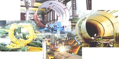
Task 1. We are surrounded by technical appliances and take modern conveniences for granted, ignoring the fact that we are rapidly exhausting our energy resources. Study the pictures and describe the role of automation and high-tech technologies nowadays.
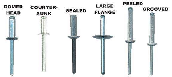
Task 7. Ask your groupmate about the objects in the picture below. Translate the terms into Ukrainian and describe the differences between these blind rivets. If you have problems, contact the dictionary or any Internet resources.
Task 12. Write two paragraphs, one about the advantages and the other about the disadvantages of such mechanical elements as rivets and belts in engineering. Describe their functions and applications. Write your report using 120-150 words. Task 13. Solve the crossword.
Task 3. Read the text. Mechanical Failure Modes Forces imposed on systems can cause failures in many different ways. Engineers have to take system and environmental forces into account when designing a system or a component, whether the system is a microchip or a skyscraper.
The ten primary modes for failure of mechanical components include: 1. Buckling – Buckling is the failure of a long, slender column that has been subjected to a compressive, axial load. As the load is applied, the center of the column span bulges outward, and then either cracks or yields, depending on the material properties of the specific component. 2. Corrosion – Corrosion is the chemical alteration (generally, but not always, oxidation), of a material due to environmental exposure to corrosive elements. For example, iron or steel that is exposed to air can undergo oxidation, forming iron oxide, commonly known as rust. This reddish-brown material has virtually no structural strength, and can reduce the effective material cross section, and therefore strength of a structure. 3. Creep – Creep is the slow deformation of a solid material over time due to applied loads and often increased temperatures. Creep can result in changes in material properties and part geometries that can cause failures. 4. Fatigue – Fatigueis a reduction in the ultimate strength of a material due to cyclic loading of a part. Micro-deformations can occur in loads that are larger than the normal working load. Even elastic deformations can result in material changes that can reduce the ultimate strength over a large number of cycles. 5. Fracture – Fracture begins as a localized microcrack in a part that slowly grows over time, or grows rapidly when exposed to a large overload. Failure occurs when the crack growth becomes critical and the part breaks. Crack growth often begins in areas of high stress concentration, such as corners. 6. Impact – Impact failure, just as it sounds, is the failure of a part due to impact with or by another object. A baseball shattering a window is an impact failure. 7. Rupture – Rupture generally occurs in pressure vessels or other containers when the pressure within the vessel exceeds the strength of a vessel, either globally or locally. Overpressure can cause rupture, as well as localized reduction in wall thickness due to corrosion or wear. 8. Thermal Shock – Thermal shock is the result of a component moving quickly from one temperature extreme to another. For example, brittle materials such as cast iron experience thermal shock if a hot part is suddenly cooled. The part can then crack or shatter because the material does not have the ductility to withstand the sudden thermal contraction of the material. 9. Wear – Wear is the gradual removal of material by two parts rubbing against each other, or environmental contact with a part, such as water or sand. As material is removed, the effective cross section of a load bearing part is reduced, increasing the stress on the part even though the applied load is constant. 10. Yielding – Yielding is the stress failure of a part due to overloading. As a load is applied to the component, the stress in the part increases. Based on the stress-strain curve for that particular material, the yield point is essentially the peak load that the part can hold before the material stretches apart. While every operating environment contains different variables, engineers need to understand the different modes of failure so that they can design their parts with a factor of safety large enough to minimize the probability of failure during normal working operations and during potential overloading conditions. Task 4. Answer the following questions and put 5 different type questions to the text: 1. What is a mechanical failure? 2. Components can fail in a variety of different ways based on geometry and load, can`t they? 3. What are ten primary modes for failure of mechanical components? 4. Give the definition to each of the ten modes. 5. What should engineers do to design parts?
Appendix 1 Grammar Reference
We use the present simple for: · facts and permanent states. Tony works for a construction company. · general truths and laws of nature. Heat flows from hot to cold. · habits and routines (with always, usually, etc.). He usually cleans the car on Sundays. · timetables and programmes (in the future). My train departs at 5.32 exactly. · sporting commentaries, reviews and narrations. Manson passes on the far side and clips the crash barrier. · feelings and emotions. I love Venice; it’s a beautiful city. The time expressions we use with the present simple are: usually, often, always, every day/week/month/year etc., in the morning/afternoon/evening, at night/the weekend, on Fridays, etc. We use the present continuous (to be+verb – ing): · for actions taking place at or around the moment of speaking. They are watching TV now. · for temporary situations. We are replacing the tiles in the bathroom this weekend. · for fixed arrangements in the near future. We’ re walking over to the next village tomorrow. · for currently changing and developing situations. The neighbourhood is becoming quieter and quieter. · with adverbs such as always to express anger or irritation at a repeated action. He is always using the hairdryer when I need it. The time expressions we use with the present continuous are: now, at the moment, at present, these days, nowadays, still, today, tonight, etc.
We use the past simple: · for an action that occurred at a definite time (stated or implied) in the past. The milkman left the milk at 7 o’clock thi9s morning. · for actions that happened immediately after one another in the past. He opened the window and shouted to his friend. · for habits or states which are now finished. My mother worked on a farm when she was younger. Note that used to can also be used instead of the past simple for habits/repeated actions in the past. The time expressions we use with the past simple are: yesterday, then, when, How long ago …? Last night/week/month/year/Friday/October etc, three days/weeks etc ago, in 1999, etc. We use the past continuous (was/were + verb-ing): · for an action which was in progress when another action interrupted it. We use the past continuous for the action in progress (longer action) and the past simple for the action which interrupted it (shorter action). We were playing cricket in the garden when it started to rain. · for two or more simultaneous actions in the past. I was preparing dinner while John was doing his homework. · for an action which was in progress at a state time in the past. We don’t mention when the action started or finished. At 7 o’clock last night, I was walking home from the gym. · to describe the atmosphere, setting, etc and to give background information to a story. The cicadas were singing and the sun was shining. I was sitting outside on the veranda when suddenly it went quiet. Note: when there are two past continuous forms in a sentence with the same subject, we can avoid repetition by just using the present participle (-ing form) and leave out the verb to be. They were walking along, they were whistling a tune. =they were walking along, whistling a tune. The time expressions we use with the past simple are: while, when, as, all morning/evening/day/week etc.
We use the present perfect (have+past participle) for: · an action that happened at an unstated time in the past. The emphasis is on the action. The time when it occurred is unimportant or unknown. I have cleaned the car. Wendy has been to Spain twice. · an action which started in the past and continues up to the present, especially with stative verbs such as be, have, like, know, etc. I have known Jack for twenty years. · a recently completed action. I have completed my History project. · personal experiences or changes. He has shaved his moustache off. The time expressions we use with the present perfect are: for, since, already, always, just, ever, never, so far, today, this week/month etc, how long, lately, recently, still (in negations) etc. We use the past perfect (had+past participle): · for an action which happened before another past action or before a stated time in the past. Peter had finished his meal by six o’clock. · for an action which finished in the past and whose result was visible at a later point in the past. He had twisted his knee a few days earlier and he was still limping heavily. · for a general situation in the past. Everything had appeared normal at first. The time expressions we use with the past perfect are: before, after, already, just, for, since, till/until, when, by the time, never, etc.
We use the present perfect continuous (have been+verb-ing): · to put emphasis on the duration of an action which started in the past and continues up to the present. We have been cutting the lawn all afternoon. · for an action which started in the past and lasted for some time. It may still be continuing or has finished already, with the result visible in the present. He’s bad-tempered because he has been overdoing things recently. · to express anger, irritation or annoyance. |


 Task 4. Listen to the description of motion control systems and try to describe the main principle of it. Give your own example of using motion control systems.
 Task 11. a) Why is it important for an engineer to know the properties of engineering materials? List the properties you know. Compare your list with that of your partner.
 Task 13. Look at the picture and write an argumentative essay (not over 100-120 words) about tool sharpening evolution. Special attention should be given to the problem of tool wear and advantages/disadvantages of modern types of sharpening.

 a) How much do you know about bearings?
 Task 2. A) The students are at the workshop on mechanical parts production. Listen to their discussion and learn what properties bearing has and where it can be used.


 Components can fail in a variety of different ways based on geometry, load direction, environmental conditions, or other variables. By understanding how something could fail, engineers can design the component to minimize the probability of failure. Designers generally use a factor of safety when designing critical parts. A factor of safety is a multiplier added to design criteria to ensure that not only does the part perform properly under normal loadings, but also performs properly under occasional overloading.