Заглавная страница Избранные статьи Случайная статья Познавательные статьи Новые добавления Обратная связь FAQ Написать работу КАТЕГОРИИ: ТОП 10 на сайте Приготовление дезинфицирующих растворов различной концентрацииТехника нижней прямой подачи мяча. Франко-прусская война (причины и последствия) Организация работы процедурного кабинета Смысловое и механическое запоминание, их место и роль в усвоении знаний Коммуникативные барьеры и пути их преодоления Обработка изделий медицинского назначения многократного применения Образцы текста публицистического стиля Четыре типа изменения баланса Задачи с ответами для Всероссийской олимпиады по праву 
Мы поможем в написании ваших работ! ЗНАЕТЕ ЛИ ВЫ?
Влияние общества на человека
Приготовление дезинфицирующих растворов различной концентрации Практические работы по географии для 6 класса Организация работы процедурного кабинета Изменения в неживой природе осенью Уборка процедурного кабинета Сольфеджио. Все правила по сольфеджио Балочные системы. Определение реакций опор и моментов защемления |
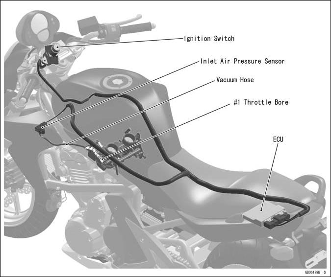
Technical Information - Inlet Air Pressure SensorСодержание книги
Поиск на нашем сайте
Atmospheric pressure sensor and camshaft position sensor are not equipped with the EX650A/B. As a substitute of these sensors above, the EX650A/B recognizes atmospheric pressure and intake stroke of #1 by the signal of inlet air pressure sensor.
The ECU detects atmospheric pressure when the ignition is switched ON. While the engine is run-ning, the ECU also presumes atmospheric pressure by analyzing the waveform of boost pressure over fixed period. The intake stroke is recognized by waveform of boost pressure, therefore the system can recognize the difference of each stroke.
GENERAL INFORMATION 1-15
Technical Information – ABS (Anti – Lock Brake System)
Outline
ABS controls the brake caliper fluid pressure by means of mechatronics - a combination of electronic and hydraulic control technology in order to keep the friction force between the tires and the road surfaces close to the maximum value and prevent wheel lock. But it does not operate during cruising.
ABS Total System
GENERAL INFORMATION
Technical Information – ABS (Anti – Lock Brake System)
ABS System Block Diagram
GENERAL INFORMATION 1-17
Technical Information – ABS (Anti – Lock Brake System)
Related Parts and Function
1. Front Wheel Rotation Sensor
2. Front Wheel Rotation Sensor Rotor
3. Rear Wheel Rotation Sensor
4. Rear Wheel Rotation Sensor Rotor
5. ABS Indicator Light (LED)
6. ABS Hydraulic Unit
7. ABS Fuse Box
8. ABS Kawasaki Self-diagnosis System Connector
Wheel Rotation Sensor
The wheel rotation sensors output the rotation speed of each wheel to the ECU in the ABS hydraulic unit. The wheel rotation sensor is installed to the front fork and rear caliper bracket, and the sensor rotor is pressed into the brake disc. The number of teeth on the front and rear sensor rotor is 50.
ABS Indicator Light (LED)
The condition or the failure of the ABS system is indicated by various patterns of the ABS indicator light (LED) blinking.
GENERAL INFORMATION
Technical Information – ABS (Anti – Lock Brake System)
ABS Hydraulic Unit
The outlet and inlet solenoid valves, reservoir, pump motor, solenoid valve relay, motor relay, and ECU are built in the ABS hydraulic unit.
1. Brake Lever
2. Brake Pedal
3. Pump Motor
4. Rear Inlet Solenoid Valve
5. Rear Outlet Solenoid Valve
6. Rear Reservoir
7. Rear Caliper
8. Front Inlet Solenoid Valve
9. Front Outlet Solenoid Valve
10. Front Caliper
11. Front Reservoir
12. Orifice
13. Filter
14. Check Valve
GENERAL INFORMATION 1-19
Technical Information – ABS (Anti – Lock Brake System)
Inlet Solenoid Valve
Inlet solenoid valves control the brake pressure of each wheel by combining the operation of the outlet solenoid valve. The ECU changes the electric current in the solenoids of the inlet solenoid valve (2 way, 2 position electromagnetic valve) to move the tappet and change the fluid pressure to “Increase Mode”, “Hold Mode”, or “Decrease Mode”.
1. Increase Mode
2. Hold and Decrease Mode
3. Tappet
4. Valve Body
5. From Master Cylinder
Outlet Solenoid Valve
Outlet solenoid valves control the brake pressure of each wheel by combining the operation of the inlet solenoid valve. The ECU changes the electric current in the solenoids of the outlet solenoid valve (2 way, 2 position electromagnetic valve) to move the armature and change the fluid pressure to “Increase Mode”, “Hold Mode”, or “Decrease Mode”.
1. Decrease Mode
2. Increase and Hold Mode
3. Armature
4. Valve
5. To Reservoir
GENERAL INFORMATION
|
||||||||||||||||||||||||||||||||||||||||||||||||||||||||||||||||||||||||||||||||||||||||||||||||||||||||||||||||||||||||
|
|
Последнее изменение этой страницы: 2016-08-10; просмотров: 282; Нарушение авторского права страницы; Мы поможем в написании вашей работы! infopedia.su Все материалы представленные на сайте исключительно с целью ознакомления читателями и не преследуют коммерческих целей или нарушение авторских прав. Обратная связь - 3.139.235.100 (0.007 с.) |