Заглавная страница Избранные статьи Случайная статья Познавательные статьи Новые добавления Обратная связь FAQ Написать работу КАТЕГОРИИ: ТОП 10 на сайте Приготовление дезинфицирующих растворов различной концентрацииТехника нижней прямой подачи мяча. Франко-прусская война (причины и последствия) Организация работы процедурного кабинета Смысловое и механическое запоминание, их место и роль в усвоении знаний Коммуникативные барьеры и пути их преодоления Обработка изделий медицинского назначения многократного применения Образцы текста публицистического стиля Четыре типа изменения баланса Задачи с ответами для Всероссийской олимпиады по праву 
Мы поможем в написании ваших работ! ЗНАЕТЕ ЛИ ВЫ?
Влияние общества на человека
Приготовление дезинфицирующих растворов различной концентрации Практические работы по географии для 6 класса Организация работы процедурного кабинета Изменения в неживой природе осенью Уборка процедурного кабинета Сольфеджио. Все правила по сольфеджио Балочные системы. Определение реакций опор и моментов защемления |
Emission control InformationСодержание книги
Поиск на нашем сайте
NINJA 650R ER-6f ABS
ER-6f
Motorcycle
Service Manual
Quick Reference Guide
This quick reference guide will assist you in locating a desired topic or pro-cedure.
•Bend the pages back to match the black tab of the desired chapter num-ber with the black tab on the edge at each table of contents page.
•Refer to the sectional table of contents for the exact pages to locate the spe-cific topic required.
NINJA 650R ER-6f
ER-6f ABS
Motorcycle
Service Manual
All rights reserved. No parts of this publication may be reproduced, stored in a retrieval system, or transmitted in any form or by any means, electronic mechanical photocopying, recording or otherwise, without the prior written permission of Quality Division/Consumer Products & Machinery Company/Kawasaki Heavy Industries, Ltd., Japan.
No liability can be accepted for any inaccuracies or omissions in this publication, although every possible care has been taken to make it as complete and accurate as possible.
The right is reserved to make changes at any time without prior notice and without incurring an obligation to make such changes to products manufactured previously. See your Motorcycle dealer for the latest information on product improvements incorporated after this publication.
All information contained in this publication is based on the latest product information available at the time of publication. Illustrations and photographs in this publication are intended for reference use only and may not depict actual model component parts.
© 2005 Kawasaki Heavy Industries, Ltd. First Edition (1): Nov. 2, 2005 (M)
NOTE ○The phrase “remove or render inoperative any device or element of design” has been generally interpreted as follows.
1. Tampering does not include the temporary removal or rendering inoperative of de-vices or elements of design in order to perform maintenance. 2. Tampering could include. a.Maladjustment of vehicle components such that the emission standards are ex-ceeded.
b.Use of replacement parts or accessories which adversely affect the performance or durability of the motorcycle.
c.Addition of components or accessories that result in the vehicle exceeding the stan-dards.
d.Permanently removing, disconnecting, or rendering inoperative any component or element of design of the emission control systems.
WE RECOMMEND THAT ALL DEALERS OBSERVE THESE PROVISIONS OF FEDERAL LAW, THE VIOLATION OF WHICH IS PUNISHABLE BY CIVIL PENALTIES NOT EXCEEDING $10 000 PER VIOLATION.
TAMPERING WITH NOISE CONTROL SYSTEM PROHIBITED
Federal law prohibits the following acts or the causing thereof. (1) The removal or rendering inoperative by any person other than for purposes of maintenance, repair, or replacement, of any device or element of design incorporated into any new vehicle for the purpose of noise control prior to its sale or delivery to the ultimate purchaser or while it is in use, or (2) the use of the vehicle after such device or element of design has been removed or rendered inoperative by any person. Among those acts presumed to constitute tampering are the acts listed below.
• Replacement of the original exhaust system or muffler with a component not in compliance with Federal regulations. • Removal of the muffler(s) or any internal portion of the muffler(s). • Removal of the air box or air box cover. • Modifications to the muffler(s) or air inlet system by cutting, drilling, or other means if such modifications result in increased noise levels.
Foreword
This manual is designed primarily for use by trained mechanics in a properly equipped shop. However, it contains enough detail and basic in-formation to make it useful to the owner who de-sires to perform his own basic maintenance and repair work. A basic knowledge of mechanics, the proper use of tools, and workshop proce-dures must be understood in order to carry out maintenance and repair satisfactorily. When-ever the owner has insufficient experience or doubts his ability to do the work, all adjust-ments, maintenance, and repair should be car-ried out only by qualified mechanics. In order to perform the work efficiently and to avoid costly mistakes, read the text, thor-oughly familiarize yourself with the procedures before starting work, and then do the work care-fully in a clean area. Whenever special tools or equipment are specified, do not use makeshift tools or equipment. Precision measurements can only be made if the proper instruments are used, and the use of substitute tools may ad-versely affect safe operation.
For the duration of the warranty period, we recommend that all repairs and scheduled maintenance be performed in accordance with this service manual. Any owner maintenance or repair procedure not performed in accordance with this manual may void the warranty. To get the longest life out of your vehicle.
• Follow the Periodic Maintenance Chart in the Service Manual. • Be alert for problems and non-scheduled maintenance.
• Use proper tools and genuine Kawasaki Mo-torcycle parts. Special tools, gauges, and testers that are necessary when servicing Kawasaki motorcycles are introduced by the Service Manual. Genuine parts provided as spare parts are listed in the Parts Catalog.
• Follow the procedures in this manual care-fully. Don’t take shortcuts. • Remember to keep complete records of main-tenance and repair with dates and any new parts installed.
How to Use This Manual
In this manual, the product is divided into its major systems and these systems make up the manual’s chapters. The Quick Reference
Guide shows you all of the product’s system and assists in locating their chapters. Each chapter in turn has its own comprehensive Ta-ble of Contents.
For example, if you want ignition coil informa-tion, use the Quick Reference Guide to locate the Electrical System chapter. Then, use the Table of Contents on the first page of the chap-ter to find the Ignition Coil section.
Whenever you see these WARNING and CAUTION symbols, heed their instructions! Always follow safe operating and maintenance practices.
CAUTION
NOTE ○This note symbol indicates points of par-ticular interest for more efficient and con-venient operation.
•Indicates a procedural step or work to be done. ○Indicates a procedural sub- step or how to do the work of the procedural step it follows. It
also precedes the text of a NOTE.
In most chapters an exploded view illustration of the system components follows the Table of Contents. In these illustrations you will find the instructions indicating which parts require spec-ified tightening torque, oil, grease or a locking agent during assembly.
LIST OF ABBREVIATIONS
COUNTRY AND AREA CODES
GENERAL INFORMATION 1-1
GENERAL INFORMATION
Before Servicing
Before starting to perform an inspection service or carry out a disassembly and reassembly opera-tion on a motorcycle, read the precautions given below. To facilitate actual operations, notes, illustra-tions, photographs, cautions, and detailed descriptions have been included in each chapter wherever necessary. This section explains the items that require particular attention during the removal and reinstallation or disassembly and reassembly of general parts.
Especially note the following:
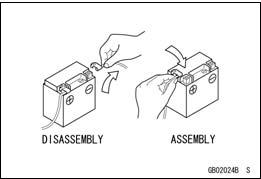
Battery Ground
Before completing any service on the motorcycle, discon-nect the battery cables from the battery to prevent the en-gine from accidentally turning over. Disconnect the ground cable (–) first and then the positive (+). When completed with the service, first connect the positive (+) cable to the positive (+) terminal of the battery then the negative (–) ca-ble to the negative terminal.
Edges of Parts
Lift large or heavy parts wearing gloves to prevent injury from possible sharp edges on the parts.
Solvent
Use a high-flush point solvent when cleaning parts. High -flush point solvent should be used according to directions of the solvent manufacturer.
GENERAL INFORMATION 1-3
Before Servicing
Storage of Removed Parts
After all the parts including subassembly parts have been cleaned, store the parts in a clean area. Put a clean cloth or plastic sheet over the parts to protect from any foreign materials that may collect before re-assembly.
Inspection
Reuse of worn or damaged parts may lead to serious ac-cident. Visually inspect removed parts for corrosion, discol-oration, or other damage. Refer to the appropriate sections of this manual for service limits on individual parts. Replace the parts if any damage has been found or if the part is be-yond its service limit.
Replacement Parts
Replacement parts must be KAWASAKI genuine or recommended by KAWASAKI. Gaskets, O-rings, oil seals, grease seals, circlips or cotter pins must be replaced with new ones whenever disassembled.
Assembly Order
In most cases assembly order is the reverse of disassem-bly, however, if assembly order is provided in this Service Manual, follow the procedures given.
GENERAL INFORMATION
Before Servicing
Tightening Sequence
Generally, when installing a part with several bolts, nuts, or screws, start them all in their holes and tighten them to a snug fit. Then tighten them according to the specified se-quence to prevent case warpage or deformation which can lead to malfunction. Conversely when loosening the bolts, nuts, or screws, first loosen all of them by about a quar-ter turn and then remove them. If the specified tightening sequence is not indicated, tighten the fasteners alternating diagonally.
Tightening Torque
Incorrect torque applied to a bolt, nut, or screw may lead to serious damage. Tighten fasteners to the specified torque using a good quality torque wrench. Often, the tightening sequence is followed twice-initial tightening and final tightening with torque wrench.
Force
Use common sense during disassembly and assembly, excessive force can cause expensive or hard to repair dam-age. When necessary, remove screws that have a non -permanent locking agent applied using an impact driver. Use a plastic-faced mallet whenever tapping is necessary.
Gasket, O-ring
Hardening, shrinkage, or damage of both gaskets and O-rings after disassembly can reduce sealing per-formance. Remove old gaskets and clean the sealing surfaces thoroughly so that no gasket material or other material remains. Install new gaskets and replace used O-rings when re-assembling
GENERAL INFORMATION 1-5
Before Servicing
Press
For items such as bearings or oil seals that must be pressed into place, apply small amount of oil to the con-tact area. Be sure to maintain proper alignment and use smooth movements when installing.
Oil Seal, Grease Seal
Do not remove pressed oil or grease seals unless removal is necessary. Replace with new ones whenever removed. Press new oil seals with manufacture and size marks facing out. Make sure the seal is aligned properly when installing.
Apply specified grease to the lip of seal before installing the seal.
Circlips, Cotter Pins
Replace circlips or cotter pins that were removed with new ones. Take care not to open the clip excessively when in-stalling to prevent deformation.
GENERAL INFORMATION
Before Servicing
Lubrication
It is important to lubricate rotating or sliding parts during assembly to minimize wear during initial operation. Lubri-cation points are called out throughout this manual, apply the specific oil or grease as specified.
Electrical Wires
A two- color wire is identified first by the primary color and then the stripe color. Unless instructed otherwise, electrical wires must be connected to those of the same color.
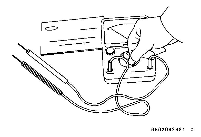
Instrument
Use a meter that has enough accuracy for an accurate measurement. Read the manufacture’s instructions thor-oughly before using the meter. Incorrect values may lead to improper adjustments.
GENERAL INFORMATION 1-7
Model Identification
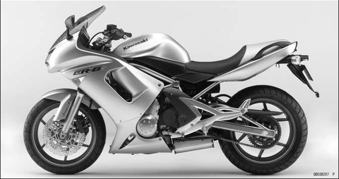
EX650A6F (United States and Canada) Left Side View
EX650A6F (United States and Canada) Right Side View
GENERAL INFORMATION
Model Identification
GENERAL INFORMATION 1-9
Model Identification
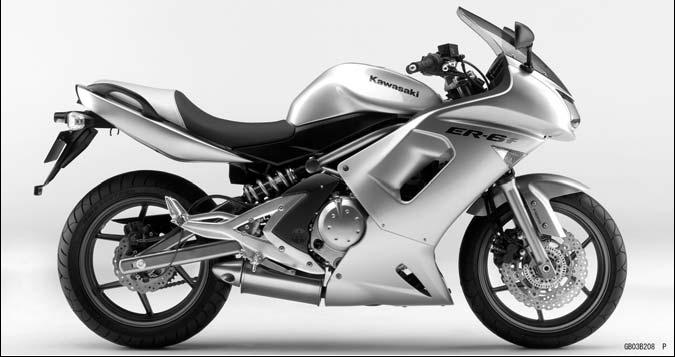
EX650B6F Left Side View
EX650B6F Right Side View
Frame Number Engine Number
GENERAL INFORMATION
General Specifications
GENERAL INFORMATION
General Specifications
Specifications are subject to change without notice, and may not apply to every country.
GENERAL INFORMATION 1-13
Cassette Type Transmission
The transmission of the current model is unable to be removed without disassembling upper and lower crankcase halves.
The EX650A/B enables transmission to be removed from the right side of engine as an assy, without disassembling crankcase halves (see Transmission Assy Removal in the Crankshaft/Transmission chapter).
Transmission Assy: Drive Shaft [A] Output Shaft [B] Shift Rods [C] Shift Dram [D] Shift Forks [E]
Transmission Case [F]
GENERAL INFORMATION
GENERAL INFORMATION 1-15
Outline
ABS controls the brake caliper fluid pressure by means of mechatronics - a combination of electronic and hydraulic control technology in order to keep the friction force between the tires and the road surfaces close to the maximum value and prevent wheel lock. But it does not operate during cruising.
ABS Total System
GENERAL INFORMATION
ABS System Block Diagram
GENERAL INFORMATION 1-17
Related Parts and Function
1. Front Wheel Rotation Sensor
2. Front Wheel Rotation Sensor Rotor
3. Rear Wheel Rotation Sensor
4. Rear Wheel Rotation Sensor Rotor
5. ABS Indicator Light (LED)
6. ABS Hydraulic Unit
7. ABS Fuse Box
8. ABS Kawasaki Self-diagnosis System Connector
Wheel Rotation Sensor
The wheel rotation sensors output the rotation speed of each wheel to the ECU in the ABS hydraulic unit. The wheel rotation sensor is installed to the front fork and rear caliper bracket, and the sensor rotor is pressed into the brake disc. The number of teeth on the front and rear sensor rotor is 50.
ABS Indicator Light (LED)
The condition or the failure of the ABS system is indicated by various patterns of the ABS indicator light (LED) blinking.
GENERAL INFORMATION
ABS Hydraulic Unit
The outlet and inlet solenoid valves, reservoir, pump motor, solenoid valve relay, motor relay, and ECU are built in the ABS hydraulic unit.
1. Brake Lever
2. Brake Pedal
3. Pump Motor
4. Rear Inlet Solenoid Valve
5. Rear Outlet Solenoid Valve
6. Rear Reservoir
7. Rear Caliper
8. Front Inlet Solenoid Valve
9. Front Outlet Solenoid Valve
10. Front Caliper
11. Front Reservoir
12. Orifice
13. Filter
14. Check Valve
GENERAL INFORMATION 1-19
Inlet Solenoid Valve
Inlet solenoid valves control the brake pressure of each wheel by combining the operation of the outlet solenoid valve. The ECU changes the electric current in the solenoids of the inlet solenoid valve (2 way, 2 position electromagnetic valve) to move the tappet and change the fluid pressure to “Increase Mode”, “Hold Mode”, or “Decrease Mode”.
1. Increase Mode
2. Hold and Decrease Mode
3. Tappet
4. Valve Body
5. From Master Cylinder
Outlet Solenoid Valve
Outlet solenoid valves control the brake pressure of each wheel by combining the operation of the inlet solenoid valve. The ECU changes the electric current in the solenoids of the outlet solenoid valve (2 way, 2 position electromagnetic valve) to move the armature and change the fluid pressure to “Increase Mode”, “Hold Mode”, or “Decrease Mode”.
1. Decrease Mode
2. Increase and Hold Mode
3. Armature
4. Valve
5. To Reservoir
GENERAL INFORMATION
Reservoir
When the passage opens between the caliper and the reservoir with the outlet solenoid valve in “Decrease Mode”, the brake fluid flows into the reservoir by pushing the piston, stays there temporar-ily, and then returns to the master cylinder. With the outlet solenoid valve “Increase or Hold Mode”, the pump returns the remaining brake fluid in the reservoir to the master cylinder.
1. From Outlet Solenoid Valve
2. To Pump
Pump Motor
The pump motor operates the pump, supply or return the brake fluid from the pump.
Pump
The pump operates continuously when the ABS is activated. The pump is driven by the motor and supply the brake fluid to the caliper or return the brake fluid in the reservoir to the master cylinder. The piston is reciprocated by the eccentric cam [A] on the end of the motor shaft and the pump sucks in or discharge the brake fluid.
When the pump pulls fluid in, the piston [B] is moved right by the force of the spring [C]. At this time, the spring [D] is compressed by the pressure of the brake fluid in the reservoir to open the inlet valve [E] and the brake fluid flows into the cylinder [F]. The outlet valve [G] is held closed by the force of the spring [H].
When the pump discharges the brake fluid, the inlet valve [E] is closed by the spring [D], and the piston [B] is moved left by the cam [A], producing pressure in the cylinder [F]. The pressure pushes the spring [H], opens the outlet valve [G], and the brake fluid returns to the master cylinder.
Spring [C]
GENERAL INFORMATION 1-21
ABS Solenoid Valve Relay
ABS solenoid valve relay supply or intercept the power to the inlet or outlet solenoid valves.
ABS Motor Relay
ABS motor relay supply or intercept the power to the pump motor.
ECU
ECU inputs the sensor signal.
ECU calculates the wheel condition for the slip.
ECU controls the hydraulic unit.
ECU sends the actuating s
|
||||||||||||||||||||||||||||||||||||||||||||||||||||||||||||||||||||||||||||||||||||||||||||||||||||||||||||||||||||||||||||||||||||||||||||||||||||||||||||||||||||||||||||||||||||||||||||||||||||||||||||||||||||||||||||||||||||||||||||||||||||||||||||||||||||||||||||||||||||||||||||||||||||||||||||||||||||||||||||||||||||||||||||||||||||||||||||||||||||||||||||||||||||||||||||||||||||||||||||||||||||||||||||||||||||||||||||||||||||||||||||||||||||||||||||||||||||||||||||||||||||||||||||||||||||||||||||||||||||||||||||||||||||||||||||||||||||||||||||||||||||||||||||||||||||||||||||||||||||||||||||||||||||||||||||||||||||||||||||||||||||||||||||||||||
|
|
Последнее изменение этой страницы: 2016-08-10; просмотров: 199; Нарушение авторского права страницы; Мы поможем в написании вашей работы! infopedia.su Все материалы представленные на сайте исключительно с целью ознакомления читателями и не преследуют коммерческих целей или нарушение авторских прав. Обратная связь - 3.15.15.91 (0.011 с.) |


 WARNING
 Indicates a conditional step or what action to take based on the results of the test or inspec-tion in the procedural step or sub-step it fol-lows.