Заглавная страница Избранные статьи Случайная статья Познавательные статьи Новые добавления Обратная связь FAQ Написать работу КАТЕГОРИИ: ТОП 10 на сайте Приготовление дезинфицирующих растворов различной концентрацииТехника нижней прямой подачи мяча. Франко-прусская война (причины и последствия) Организация работы процедурного кабинета Смысловое и механическое запоминание, их место и роль в усвоении знаний Коммуникативные барьеры и пути их преодоления Обработка изделий медицинского назначения многократного применения Образцы текста публицистического стиля Четыре типа изменения баланса Задачи с ответами для Всероссийской олимпиады по праву 
Мы поможем в написании ваших работ! ЗНАЕТЕ ЛИ ВЫ?
Влияние общества на человека
Приготовление дезинфицирующих растворов различной концентрации Практические работы по географии для 6 класса Организация работы процедурного кабинета Изменения в неживой природе осенью Уборка процедурного кабинета Сольфеджио. Все правила по сольфеджио Балочные системы. Определение реакций опор и моментов защемления |
Proposals for the selection of equipment for communicationСодержание книги
Поиск на нашем сайте
3.1.1 The main function module SDH networks
The main function module is a multiplexer SDH networks. The term itself is used as a multiplexer for the multiplexers that are used to build (multiplexing) a high speed flow of the low-speed and disassembly (demultiplexing) the high-flow in order to separate low-speed streams. SDH multiplexers in contrast to conventional multiplexers are used, for example, in the PDH network, as a function properly operate the multiplexer and the terminal access function devices, allowing low-speed channels PDH connect directly to their input ports. They are more versatile and flexible devices that perform tasks other than multiplexing and switching problems still, concentration and regeneration. Accepted, however, to distinguish two main types of multiplexer: terminal multiplexer and the multiplexer input - output. Terminal Multiplexer (TM) is a multiplexer and terminal SDH network with the access channels, the appropriate tribes PDH and SDH. TM can be administered or channels, that is, switch them with tribnogo interface input to line input or output channels, that is, switch them with a linear input to output tribnogo interface. Typically, this is limited to switching tribes 1,5 and 2 Mbit / s. Another important feature of the multiplexer is the presence of two optical line outputs (reception / transmission channels), called aggregate outputs and used to create one hundred percent redundancy mode, or the protection of 1 + 1 in order to increase reliability. The multiplexer input / output (ADM) has the same inlet tribo set as a terminal multiplexer. It allows you to enter and display the corresponding channels. In addition to switching capabilities provided by TM, the ADM allows a through switching output streams in both directions, as well as to the closure of the channel on the receiving channel on both sides in the case of failure of one of the directions. Finally, it allows (in case of accidental failure of the multiplexer) to skip the main optical flow by themselves in the bypass mode. Consider options for the acquisition of synchronous multiplexers: SDM-1 (ECI Telecom, Israel), SMA-1 R2 (Siemens, Germany) and FOX-1640 (Alcatel, Germany). The comparison results are summarized in Table 1 [PV]. Currently, due to the high saturation of the market of telecommunications, equipment selection problem ceases to be purely technical and economic challenge and becomes a component of policy makers in relation to suppliers. In this thesis project we propose to use the SDM-1 equipment company ECI Telecom (Israel), because this site is part of a single zone network route Stepnogorsk-Kokshetau. Multiplexer SDM-1 consists of the following sections (Table 3.1):
Table 3.1-SDM-1 multiplexer Sections
Each SDM-1 is a unit located on the same shelf, which may contain from 21 to 63 component interfaces with a transmission speed of 2 Mbit / s, three - 34 Mbit / s, three - 45 Mbit / s, one - 140 Mbit / s or one - 155 Mbit / s (STM-1), and certain combinations of these interfaces. Since STM-1 standard allows a maximum of 155 Mbit / s aggregate line, the number of supported component interfaces (with protection) in a given moment of time is more limited: either 63 to 2 Mbit / s, three 34 Mbit / s, three 45 Mbit / with one 140 Mbit / s, a completely filled 155 Mbit / s, four partially filled with 155 Mbit / s, or some combination of these interfaces, in an amount not exceeding the STM-1 rate. Using two modular line in an unprotected mode, you can increase the total number of supported component interfaces. In addition, SDM-1 provided more bandwidth can serve the purpose of dynamic allocation in response to changing traffic requirements.
Aggregate interfaces provide access to the lines connecting the mounting location of various SDM-1. The interface works with SDH data rate STM-1 (155.52 Mbit / s). When combined with a fiber-optic cables 1 from one another SDM SDM system 1 located in a remote location using optical aggregate interfaces. At shorter distances in this connection, instead you can use the optical electric aggregation channel. Eight slots provided for component boards. Additional fees may give the opportunity to save on administrative costs because the network provider can place these or other additional fees in the system and enter them into operation as the demands from the traffic. SDM-1 is monitored and controlled by the CPU, which communicates with the various parts of the system and the outside world. The system software is stored on the memory card that allows you to frequently and easily update the software by downloading from a remote source. Software communication management software is based on a seven-element model of OSI, working in a UNIX environment. In normal operation, the system synchronizes to choose the source of synchronization. With this source connected a voltage controlled crystal oscillator, which generates an internal clock signal to SDM-1, and the time for SDH transmission line. This source can be an external timer signal, a component signal or SDH line signal. If synchronization sources are unavailable, SDM-1 is able to maintain standby mode with the stability of 4,6 ppm (parts per million). SDM-1 is powered -48 or -60 VDC from the external battery system. The system's power structure implemented the principle of distributed architecture, ie, each card has its own built-in power supply. This achieves low cost and low power consumption in a partially filled SDM-1 configurations. An important property of sequentially implemented in the system is its modularity. As already mentioned, all the component boards are completely interchangeable, and therefore can be installed in the same slots, regardless of the exchange rate supported by them. SDM-1 architecture is similar to the architecture of the SDM-4 company ECI Telecom, which provides a family of products that are compatible with each other, and cost-effective in terms of maintenance and spare parts. Most boards are interchangeable with boards SDM-4, which makes it easy to modify the system. Proposals on Timing of SDH network sources listed at the end of the explanatory note [PG].
3.1.2 Proposal for the selection of the radiation source and photodetector
There are two types of semiconductor light sources, light emitting diodes and lasers. For the fiber optic portion of Stepnogorsk Kokshetau, you need to select as a radiation source laser. The laser has a high speed and a narrow spectrum width. From the family of semiconductor lasers is best to choose lasers with distributed feedback. These lasers operate in single-frequency mode, the emission spectrum width is less than 0.5 km. Temperature instability wavelength lasers with distributed feedback amounts to about OD km / k. The level of the output radiation, lasers powerful version highly varies within 3 to 6 dB m. As the photodetectors in optical fiber communication systems using semiconductor p-i-n photodiodes and avalanche photodiodes. These devices are small and fairly well joined to optical fibers. The p-i-n photodiodes each absorbed photon creates a pair of "electron-hole". In avalanche photodiodes internal amplification of the signal occurs, since they are designed so that they formed a region with a strong electric field E (3 x 10⁶ V / cm). In this field, the electrons generated by the light, are accelerated to energies sufficient to impact ionization of atoms of the crystal lattice. The resulting ionization of the free carriers is also accelerated and give birth to a new pair. This avalanche process leads to the fact that the absorption of a photon generates more than one electron-hole pair, and the tens and hundreds. Thus, by using a highly sensitive avalanche photodiodes as photodetectors version designed for fiber optic link, you can change the input level from - 39 to -17 dBm.
Using lasers with distributed feedback and avalanche photodiodes can get quite large regeneration areas that allow IUU fishing to place in the settlements. In Kazakhstan, the distance between the settlements can be up to 250 km. In this case, the power transmission system margin may be insufficient for covering this distance. In such cases it is possible to use optical amplifiers and preamplifiers. The main equipment optical amplifying element is an optical waveguide fiber doped with erbium. Figure 1 shows a functional block diagram of an optical amplifier [PD]. Figure 2 is a functional diagram of an optical preamplifier. The input optical signal in a location with the pumping laser beam enters the optical fiber doped with erbium, wherein the light energy is redistributed between radiations [PD]. Further, through the optical isolator radiation enters the optical bandpass filter tuned to the operating wavelength, wherein the removal of parasitic modes occurs. The input level varies from -45 dB to -15 m. In the case of using an optical preamplifier is used as a photodetector APD power standard. The output level changes from +12 to +15 dBm. An optical preamplifier used in conjunction with an optical amplifier, while the optical amplifier can be used separately.
3.2 Welding questions, and measurement of the optical fiber connection
We have said that optical cables are manufactured certain dliny called construction. Usually it does not exceed 4... 5 km (for transoceanic fiber optic - 50 km). optic line length in the overwhelming number of cases exceeds the building many times. Therefore optic cables laid in the sewer, the ground or hung on poles, you must soedinyat, t. E. To splice together. For this optical fiber end is freed from QA module length and 0.5... 1.0 m and interconnected "torets-end" by means of welding or gluing. Above it was said that optical cables are made of a certain length, which is called building. Usually it does not exceed 4... 5 km (for transoceanic fiber optic - 50 km). optic line length in the overwhelming number of cases exceeds the building many times. Therefore optic cables laid in the sewer, the ground or hung on poles, must be connected, ie. E. To splice together. For this optical fiber end is freed from OC module length and 0.5... 1.0 m and interconnected "butt-end" by means of welding or gluing. To carry out welding or bonding, optical fiber length of about 1 mm from the end of the release of the containment, and then using a special tool - the cleaver produce shearing fibers. The purpose of this operation - to get a flat end perpendicular to the axis of 0V. Removing the shell 0V, release it from the module OK, cleaning of a hydrophobic gel and other necessary operations are performed using a set of tools placed in a special suitcase - case. Fiber-to-end welding is carried out in a special welding machine. Modern welding machines for welding OB automatically perform the optimum mutual alignment RH choose the optimal welding parameters and monitor losses in spot welding. The welding process can be monitored visually in two coordinates on the liquid crystal display. These operations are carried out, for example, welding machine manufactured by FUJIKURA presented in Figure 3.1
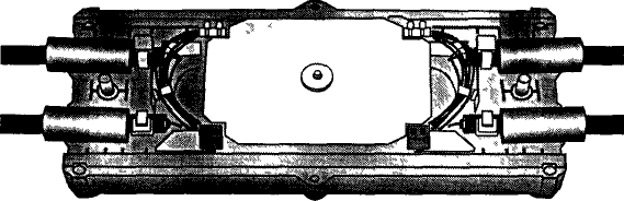
Figure 3.1 - The welding machine manufactured by FUJIKURA Place splicing spetsialnom fixed in the device, which is a heat-shrinkable tubing with a metal reinforcing rod, or in a special clip - metal V-shaped bracket. United thus the optical fibers are placed in special trays, and they in turn in a special container, which is also fixed to those ends OK sections where it is not removed the protective outer shell. Such a container is called the optical coupling. There are various designs optical coupling. Figure 3.2 shows the optical coupling FUJIKURA production, in Figure 3.3 - the KRONE optical coupler.
Figure 3.2- The optical coupler connecting production FUJIKURA
Figure 3.3 - Optical coupling KRONE firms Measurement of loss in optical fibers and cables are currently engaged in one of two ways. The first - a two-point measurement method, which is divided into three types - the breaking of the method, and the method calibrated hitless dispersion. Of these, the most widely used as a hitless nondestructive measurement method. When measuring the attenuation or OB OK RH input end of the test cut in the optical connector. This connector is connected with the reference emitter stabilized optical power and wavelength. To the output end OM, as the split in the OR, connect a calibrated optical power meter. Since the reference value of the power of the radiation source is known - Rae, is counting losses in OB negligible, we can assume that Pr = Pin. The measured output power value - Pout. Attenuation OF or OC is determined from the relationship:
Devices that produce such measurements are part of an optical tester. Optical testers are available in two versions: - Option 1 - a reference transmitter and optical power meter is placed in a single package (eg, AQ215, company ANDO, Japan); - Option 2 - a reference transmitter and optical power meter available in different housings, as two separate device (model K2702, K2503, K2505 and SIEMENS devices DIAMOND series, the company LONIIR, Russia and FOD, Russia). Gauges of the power in these kits have two calibration - in power units of milliwatts and dBm (dBm - power level in dB relative to the magnitude Popt = 1 mW). In practice it is more convenient to use the 2nd calibration. At the same time measure the power level of the transmitter output in dBm, then - the power level at the output of OB or OK. Subtracting the second reading of the first, to give the desired result.
The described method of measurement accuracy differs. Its main drawback - the need for access to both ends of the OK, it is often inconvenient for linear measurements. Currently, the most widely used method of attenuation reflectometry measurements based on the measurement of that part of the Rayleigh scattering in the OB, which is circulated in the opposite direction (reverse). For this purpose, the fiber is introduced periodic sequence of optical pulses of duration and repetition period T. At the same time to the input end OM will return pulses at each time point. These pulses time lag from the input (reference pulse), reflected from the input end planes for a period of time equal to the double pulse to travel - in forward and backward directions. If the x-axis represents time (starting from t = 0 to the reference pulse), and the vertical axis - the average values of the amplitudes of these pulses for each value of the time, you get the so-called trace. If the attenuation coefficient and backscatter coefficient at a given A for the fiber under test is constant along its length, the curve (trace) decreases from the beginning of OB exponentially. Scattering - statistical process. Therefore, the value of the pulse amplitude (ordinate) for the same time axis values (distances) will have some dispersion in each count (with periodic repetition of the probing pulses). Due to the statistical averaging of a large number of samples can be obtained pure line (exponential) dependence of the damping of the length of OB. However, an exponential curve to use awkward and difficult. So after averaging each sample is subjected to the logarithm operation, resulting in exponential (decaying) becomes the slope of the line. Thus counts on the ordinate calibrated in decibels. In the case where the reverse attenuation and Rayleigh scattering coefficients have sharp local change that indicates the presence of local inhomogeneities in OF, they appear on the trace in the form of steps or pulses. Figure 3.4 shows an example of the trace mode optical fiber length of 18.84 km.
Figure 3.4- Trace optical fibers 18,84 km
One of the advantages of the OTDR measurement method is that it is enough to have access to one end IA. Furthermore, using the OTDR can determine the distance to the local inhomogeneities, route length, length distribution inhomogeneities OF. Modern OTDRs made a number of leading world companies:. ANDO (Japan), HEWLETT PACKARD, WAVETEK WANDEL & JGOLTERMANN, IIT, Minsk, Belarus, etc. Figure 3.5 shows a general view ANDO OTDR production.
Figure 3.5-OTDR company Anritsu (ANDO) Measurement of chromatic dispersion. For modern trunk (zonal) PLAYBACK main factor limiting the length of the regeneration area is not fading, and introduced optic chromatic dispersion. The energy loss of an optical signal propagating in the CC compensated by use of intermediate optical amplifiers. In the process of propagation of optical pulses as a result they increase the duration of the chromatic dispersion. If the duration of the optical pulses becomes greater than the duration of a clock interval digital signals begin to cause errors in information transmission. For transmission systems with speed STM-16 with a duration clock period Currently, according to Rec. ITU-T G.650, used three methods of chromatic dispersion measurement. Currently, devices for measuring the chromatic dispersion produced by the following companies, and types of these devices are shown in Table 1 [PD].
Polarized mode dispersion (PMD) PMD measurement value.For there are several methods: 1) Fourier transform method; 2) wavelength scanning method; 3) a method of analysis parameters Stokes; 4) method of Poincaré sphere analysis; 5) a method of analysis using the Jones matrix. Such an amount of PMD measurement methods due to the fact that the need to measure arose relatively recently, due to the rapid increase in the speed and range of information transfer. This also explains the fact that, to date devices for PMD measurement is almost there. The first company, which started production of equipment for the measurement of the PMD, is HEWLETT PACKARD - it has developed and launched a NR8509V device. The device with similar functions - AQ6330 released and the firm AN DO. The operation of these devices is based on two methods - wave scanning and analysis of the Jones matrix. The measurement results are displayed on the display device in the form of curves PMD dependencies. Compound of lengths of optical cable construction. Construction length of fiber optic cables for terrestrial FOTS. usually in the range of 3-6 km. (For submarines, especially for sea and ocean, - up to 25 km). The combination of these lengths is performed with the help of special devices, optical couplers (see. Figures 3.2 and 3.3). To this end, the ends of fiber optic cables that are designed for connecting (splicing) are exempt from the protective sheaths and reinforcing elements over a length of up to 0.5 m. Liberated optical fibers are thoroughly cleaned by washing with special fluids and tissues. In this case must necessarily be hydrophobic filler is removed from the optical fiber surface. To carry out these operations produced a set of special tools (see. Figure 3.8).
Figure 3.8 - Tool Kit for installation of optical cable Below is a list of all necessary instruments, appliances and materials necessary for operations splicing of optical cables and fixing them all in the coupling. Figure 3.9 shows the tools for cutting an optical cable: removal of the outer protective shell, remove shells modules, trimming Kevlar. With these tools, removed protective sheath fiber, then using a cleaver shown in Figure 3.10, is the fiber peeling for a flat end perpendicular to the axis of the fiber.
Figure 3.9- Tools for cutting an optical cable
Figure 3.10- Optical fiber cleaver Fujikura CT-02 Protective coating is removed from the fiber over a length of 15-20 mm. The following operation - on one of the fibers puts special tube -. Heat-shrinkable sleeve of the reinforcing element (typically a steel rod with a diameter of 1.0-1.5 mm diameter sleeve is 4.3 mm, length 30-50 mm (this operation can be performed RH before processing ends). The treated fiber ends are fixed in special clamps welding machine (Figure 3.1) and is made of welding. In the process of welding is one of the specialists is at the other end of the length of the building OC, and monitors the quality of welding using a OTDR, communicating with the operator, producing welding special optical phone. This phone is connected to an optical fiber through its side surface at the bend. The criterion of the quality of welding is the magnitude of the losses introduced by the welding spot. They must conform to established standards (no more than 0.1 dB). After receiving the quality of welding is coming to this place heat-shrinkable sleeve, after which she, along with the fiber is placed in a special heating device, which is part of the welder, and anchoring is done shrinking sleeve. The resulting compound was placed in the grooves in the coupling for fastening.
|
||||||||||||||||||||||
|
|
Последнее изменение этой страницы: 2016-08-01; просмотров: 82; Нарушение авторского права страницы; Мы поможем в написании вашей работы! infopedia.su Все материалы представленные на сайте исключительно с целью ознакомления читателями и не преследуют коммерческих целей или нарушение авторских прав. Обратная связь - 52.14.213.73 (0.011 с.) |


 dB
dB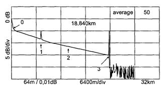

 = 400 ns expansion of optical pulses above this value begins with a length of more than 235 km section of a fiber G.652 and 800 nm - For G.655 OB by direct current modulation of the laser pump radiation. For STM-64 (10 Gbit / s) - respectively 36 km and 125 km of G.652 G.655 (for this rate
  = 100 ps). To increase the length of the regeneration area requires the use of compensation of chromatic dispersion, which entails the need to increase the gain of optical amplifiers, dispersion compensators as making large attenuation. Increasing the number of optical amplifiers besides increasing noise and also leads to an additional chromatic dispersion. From this it is evident the need for measuring the chromatic dispersion of optical pulses in the optical path FOTS.