Заглавная страница Избранные статьи Случайная статья Познавательные статьи Новые добавления Обратная связь FAQ Написать работу КАТЕГОРИИ: ТОП 10 на сайте Приготовление дезинфицирующих растворов различной концентрацииТехника нижней прямой подачи мяча. Франко-прусская война (причины и последствия) Организация работы процедурного кабинета Смысловое и механическое запоминание, их место и роль в усвоении знаний Коммуникативные барьеры и пути их преодоления Обработка изделий медицинского назначения многократного применения Образцы текста публицистического стиля Четыре типа изменения баланса Задачи с ответами для Всероссийской олимпиады по праву 
Мы поможем в написании ваших работ! ЗНАЕТЕ ЛИ ВЫ?
Влияние общества на человека
Приготовление дезинфицирующих растворов различной концентрации Практические работы по географии для 6 класса Организация работы процедурного кабинета Изменения в неживой природе осенью Уборка процедурного кабинета Сольфеджио. Все правила по сольфеджио Балочные системы. Определение реакций опор и моментов защемления |
Analyses of the current situation on the project and the development of their technical realizationСодержание книги
Поиск на нашем сайте
Introduction
Communication of Kazakhstan to a qualitatively new stage of historical development is determined by the new geopolitical situation. The basis of Kazakhstan's telecommunication is interconnected communication network, ensuring the provision of users of telecommunications services in the country. Interconnected communications network - the complex conjugate technology telecommunications public networks and private networks with a common centrally managed, regardless of departmental affiliation and forms of ownership. The first fiber-optic communication line (FOCL) in the CIS countries were built in the early 80-ies of XX century, based on the use of multimode optical fiber, mainly it was the connecting link between the nodes of the СTS network using a 30-channel digital system transmission "Sonata". Although originally mortgaged service life FOCL was not less than 25 years, however, for the stable functioning of the transmission system required to maintain fiber-optic characteristics within acceptable limits. The first fiber-optic trunks were laid mainly in the city and had a small extent, usually no more than 1-2 km. Inherent cable with multimode fiber mode dispersion of the signal, used for low-speed (2 or 8Mbit / s) transmission systems for short distances was a small amount and is not needed in the measurement. Locating a fault in the trunk of small extent, laid on the cable duct, made by visual inspection. The situation changed radically with the advent of the 90-ies of XX century for telecommunication systems a single-mode fiber (having less kilometric attenuation and dispersion on the order of magnitude smaller compared to multimode fiber) and high-power laser sources. The length of the fiber-optic sections without of regeneration increased to tens of hundred kilometers, digital signal transmission rate, realized in the emerging systems of transmission of synchronous digital hierarchy (the SDH), reached 622Mbit / s (STM-4 level) and above. Also changed the concept of the construction of communication networks, have become the basic ring and mixed (ring + linear) topology, giving new opportunities to create backup routes of transmission of telecommunications traffic. In Kazakhstan, the start of construction of the first fiber-optic lines with single-mode type optical fiber in the second half '90s, it was the main line of long-distance communication. Digital transmission systems (DTS) are characterized by excellent information from analog systems properties. The main advantages of these systems are the following: a higher noise immunity, which can significantly alleviate the requirements for signal propagation conditions on the transmission line; be integrated messaging and switching systems; negligible impact of the transmission line parameters on the channel characteristics; the possibility of using modern technology in hardware DTS; the absence of the phenomenon of accumulation of noise and distortion along the transmission line; a simple terminal equipment as compared to equipment of transmission systems with frequency division multiplexing (FDM); ease of classification of information transmitted. In this thesis the issues of modernization of the site zonal networks Stepnogorsk-Kokshetau based fiber-optic line. Operated on site equipment K-60 with a transmission medium (electrical cable) does not meet the requirements for the quantity and quality of channels.
Annotation
In this thesis project developed questions to modernize the network of zonal communication lines in the area, Kokshetau Stepnogorsk network with prospective optic cable. The design calculations were made of the communication channels, and a portion of the length of the main parameters of regeneration of the optical fiber. A transmission system (FOTS), is given a brief description of it. We present issues welding, measuring and connection of the optical fiber, as in the project addressed issues of occupational health and safety of life.
Composed of a feasibility study of the project, which characterizes the economic feasibility of the project.
Analyses of the current situation on the project and the development of their technical realization Project Formulation of the problem As mentioned above (Section 1.1), there was a strong need for communication channels in this area, that is, to increase the bandwidth capacity of the link. In addition, one should also note that the quality of communication in this area is poor. Therefore, in this project it is necessary to develop the following issues: selection of the route for laying fiber-optic; definition of requirements in communication channels at a projected fiber optic; choice of optical fiber and cable brands; calculation of the dispersion properties of the fiber and definition of the actual dispersion and attenuation in the line, the calculation of these data regenerator section length; offer a variety of communications equipment, with the necessary factors; Analysis of factors affecting the safety of the personnel working in the construction and operation of communication lines, as well as on the protection of the environment; determine the economic parameters of the project.
Primary BCC network
To construct a communication network are required so-called transmission system, ie apparatus through which connection lines for creating channels and group paths. And then arrange of lines and nodes and terminal stations, primary and secondary telecommunications network. Primary networks consist only of lines, regeneration (amplification) and channeling equipment at the stations. Secondary network comprise further switching nodes allowing to switch communication channels to multiple destinations. But already on the basis of secondary networks are numerous communication services, providing a variety of services. Communication lines laid between the cities and in the major cities, intermediate regeneration (amplifier) Items endpoints - all primary network, serving for standard analog and digital channels and paths. Primary BCC network (interconnected network) is divided into the trunk, zonal and local area network (Figure 1.2).
Figure 1.2 - Backbone, zonal and local primary network
Typical telecommunication channels have the same characteristics, regardless of at what portion of the primary network are formed: these characteristics are strictly standardized and accurately performed. Standardized telecommunication channels a lot, but we are referring only two: the analog channel voice frequency (VF channel) with a bandwidth of 0,3-3,4 kHz and the main digital channel, the bandwidth is 64 kbit / s. Along the lines of the primary network connection is formed such channels. You can create and broadband analog channels, digital channels and with greater bandwidth, but the vast majority of available channels is as follows. the secondary network is organized on the basis of the above-mentioned basic channels: telephone, telegraph, data transmission, faxes. The number of telecommunication services is growing right before our eyes, and now their number was thirty. To name just a few: city, intercity and international telephone, telegraph subscriber (so-called "TTY"), telex, teletex, telefax, bureaufax, videotex, etc. Of course, the biggest secondary network and the most numerous services - telephone. Most of the PM and digital channels in the country (it is necessary to think and abroad) are used for the formation of telephone networks. Moreover, often thought (evidenced by many publications) that the telephone network - the only secondary network, the other is not there. In fact this is not true: there are telegraph network - work on them telex (subscriber telegraph) and telegraph service in all offices. Any data transmission network, and not only with the rate of 64 kbit / s, but higher speed, e.g. 2048 kbit / s (E1 channel).
The technical part
2.1 Fiber-optic communication lines
2.1.1 Overview FOL
In fiber optic transmission systems (FOTS) information is transmitted by electromagnetic waves of high frequency, approximately 200 THz, which corresponds to the near infrared range of the optical spectrum of 1500 nm. Waveguides, transferring the information signals to the FOTS is an optical fiber (s) that has the important ability to transmit light at long distances with low losses. Losses in the OB quantitatively characterized by attenuation. Speed and distance data transmission are defined distortion of optical signals due to dispersion and attenuation. Fiber-optic network - is an information network that links between the nodes which are fiber-optic communication lines. Technology of optical fiber networks in addition to the issues of fiber optics also cover issues relating to the electronic transmission equipment and its standardization, communication protocols, network topology issues and general issues of networking. Optical fiber is now considered the most advanced physical medium for the transmission of information, as well as the most promising medium for transmission of large data flows over long distances. The grounds to think so derived from a number of features inherent in optical waveguides: - Broadband optical signals due to the extremely high carrier frequency Hz. This means that the optical link can transmit information at a bit rate of the order / s (1Tbit / s). In other words, a single fiber can transmit 10 million simultaneous phone calls and a million video. The data rate can be increased by transmitting information in two directions, as the light waves can propagate in the same fiber independently. Furthermore, in an optical fiber can propagate light signals of two different polarizations, which allows to double the capacity of an optical link. To date, the limit on the density of information transmitted through the optical fiber is not reached; - Very small (compared to other fluids) attenuation of the light signal in the optical fiber. The best examples of Russian fibers have attenuation of 0.22 dB / km at a wavelength of 1.55 microns, which allows you to build a link length of up to 100 kilometers without regeneration of signals. For comparison, the best Sumitomo fiber at a wavelength of 1.55 microns has attenuation 0.154 dB / km. In US optical laboratories developed more "transparent", so-called optical fluorozirconate fiber having a theoretical limit of about 0.02 dB / km at a wavelength of 2.5 microns. Laboratory studies have shown that on the basis of these fibers can be created a communication link with regeneration through portions 4600 km at a transmission order of 1 Gbit / s speed; - OM made of quartz, which is based on silica, widely distributed, and inexpensive material because, unlike copper; - Optical fibers have a diameter of about 100 microns, that is very compact and lightweight, which makes them promising for use as aviation, instrumentation, in cable technology; - Since the optical fibers are insulators, therefore, the construction of communications systems is automatically achieved by isolation segments. In the optical system are completely electrically isolated from each other, and many of the problems associated with the earth and lifting capacities, which still occurred when connecting electrical cables, become irrelevant. Applying extra strong plastic for cable factories made self-supporting overhead cables that do not contain metal and thus safe in electrical terms. Such cables can be mounted on the masts of the existing power lines, both separately and integrated in the phase wire, saving significant funds for laying cable across rivers and other obstacles; - Communications systems based on optical fibers are resistant to electromagnetic interference, and the information is transmitted over optical fibers is protected from unauthorized access. Fiber-optic communication lines can not listen in a non-destructive way. Any impact on the OB can be detected by monitoring (continuous monitoring) line integrity; - An important property of optical fiber - longevity. Fiber life time, that is, preservation of its properties within certain limits, more than 25 years that allows to lay an optical fiber cable and one time, as needed, to increase channel capacity by replacing receivers and transmitters at a high-speed. But there are also some disadvantages of fiber optic technology: - When creating link requires highly active elements which convert electrical signals into light, and a light to electrical signals. To connect with OM transceiver equipment used optical connectors (connectors), which should have low optical losses and a great resource for connection-disconnection. Errors in the manufacture of such link elements must be of the order of a micron, i.e. meet the emission wavelength. Therefore, optical communication lines the production of these components is very expensive; - Another drawback is that the precision required, and therefore expensive, process equipment for the installation of optical fibers. Consequently, when an accident (breakage) of the optical cable, the cost of higher recovery than with copper cables. The advantages of the use of fiber-optic communication lines (FOCL) are so significant that in spite of these shortcomings of the optical fiber, the communication lines are increasingly being used to transmit information.
2.1.2 Structural features FOC
One of the most important components of fiber optic is a fiber-optic cable (FOC). The defining parameters in the production of the FOC are the operating conditions and the capacity of the link. Under the terms of operation of the cables are divided into: installation, station, zonal, long-distance.
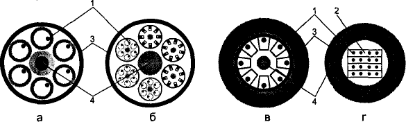
The first two types of cables are designed for installation inside buildings and structures. They are compact, lightweight and usually have a small construction length. Cables for the last two types are designed for installation in the wells of cable communications in the ground, on poles along the transmission line under water. These cables are protected from external influences and the construction length of over two kilometers. The above features and requirements determine the design and type of optical cables. Currently, conventionally there are four types of structures OK (arbitrarily because in arrangement of optical fiber and for other purposes, they can be divided into a larger number of types and designs) [14, 15]: a) concentric layer cable; b) beam lay cables; c) cables with the relevant carrier cores; g) ribbon cables.
Figure 2.1 shows sketches of optical cable cross-sections of different types: type "a" and "b" refer to the classic design, the types of "c" and "d" characteristic of most optical cables.
1 - optical fiber; 2 - modules; 3-plastic tube; 4-power element. and - concentric layer; b - twist beam; a - a core profile; g - belt
Figure 2.1 - Typical optical cable construction
OK "a" is in the form of coils of optical modules, twisted around the central reinforcing element. Such a construction is effective when the number of the optical modules is not more than 20. Typical concentric layer OK has an outer diameter of 12 mm and 6 to 8 optical modules. The optical module is a polymeric tube with a freely laid fiber in it. Optical type "b" of the cable is made up of bundles of optical modules, concentric around a central reinforcing core. The beam is a polymeric tube, inside which there are profiled with longitudinal grooves cores. In these grooves the optical fibers are loosely housed. Unlike OС twisting concentric layer, helix in the optical cable module type "b" have the same direction and pitch. This type of cable contains 25-50 modules in standard design - 40. The external diameter is 15... 25 mm. Optical cable type "c" consists of a core, which is a plastic bearing element with helical grooves into which freely without tension, with the primary fibers are laid containment or optical modules with a diameter smaller groove width. Core optical fibers or modules of insulating tape is wound and covered with a sheath. In some designs OK reinforcing core has a circular cross section around which a spiral wound gasket with alternating there between lie freely optical modules. The cables 'in' type typically contains 8-10 fibers. Their outer diameter - 20 mm. Сore type cables "d" is assembled from individual flat ribbons with parallel at a distance from each other in a few tenths of a millimeter waveguides. Twisted ribbon cable form the core. The reinforcing elements are located in a sheathed OK. Due to the dense packing of the cable of this design can be manufactured with a very small diameter. Thus, cable 144 of the optical fibers has an outer diameter of 12 mm. The small core sizes allow for layout in combination with other elements of the cable Each of the considered OK types has its own advantages and disadvantages. Their use in each case is dictated by the installation conditions, the operation and the nature of the problem being solved. To provide high bandwidth communication line produced FOC containing a small number (8) of single mode fiber with low attenuation, and cables for distribution networks may comprise up to 144 filaments as a single-mode and multi-mode, depending on the distances between network segments [12].
2.1.3 Distribution of light beams in optical fibers
Optical fiber (Figure 2.1) consists of a core, in which the propagation of light waves, and a cover designed, on the one hand, to create the best conditions for reflection at the interface "core - shell", and the other - to reduce the radiation energy in the surrounding space. In order to enhance the strength and thus the reliability of the fiber over the shell, usually superimposed reinforcing protective coating.
Figure 2.1 - General view of the model RH
This design is used in most RH optical cable (OK) as the underlying core is made from optically denser material. Optical fibers are characterized by a core diameter and the cladding and core refractive index profile, i.e. the dependence of the refractive index of the distance from the axis OB (Figure 2.3) [13].
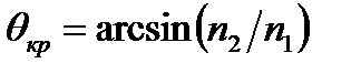
All optical fibers are divided into two main groups: multimode MMF (multi mode fiber) and singlemode SMF (single mode fiber). In multimode OB having a light-carrying core diameter on the order more transmission wavelengths, distributed a number of different types of light rays - mod. Multimode fibers are separated by the profile of the refractive index in the step (step index multi mode fiber) and gradient (graded index multi mode fiber). The main factors affecting the nature of light propagation in the fiber, along with the emission wavelength, are the geometric parameters of fiber, attenuation, dispersion. The principle of the propagation of optical radiation along the optical fiber based on the phenomenon of total internal reflection at the interface with different refractive indices. The propagation of light beams in an optically denser medium surrounded by a less dense shown in Figure 2.2. The angle of total internal reflection, in which the incident on the border of the optically denser and an optically less dense medium is totally reflected light is determined by the relation
where n1 - the refractive index of the core RH; n2 - refractive index of the shell RH, and n1> n2.
Figure 2.2 - Distribution of radiation and by stepwise gradient multimode and singlemode OС
If you get on the end of the light emission RH it can spread three types of light beams, called guides and attendant emitted rays, the existence and prevalence of any type of rays determined by the angle of incidence on the interface between the "core - shell". Those rays which fall on the interface at an angle (rays 1, 2 and 3), and are reflected from it again back into the fiber core, and propagates in it without undergoing refraction. Since the path of the rays is completely located within the propagation medium - core fiber, they are spread over long distances and are called rails. Rays incident on the interface at an angle (rays 4), are called flowing rays (rays of the shell). Reaching the boundaries of the "core - shell", these rays are reflected and refracted, each time losing sheathed fiber portion of the energy, and therefore disappear completely at some distance from the fiber end. The rays that are emitted from the shell to the surrounding space (5-rays) emitted rays are named and appear in places of irregularities or curling due RH. Radiated and the resulting beams are parasitic and cause dissipation of energy and the distortion of the information signal.
2.1.4 Modes propagating in optical waveguides
In general, the propagation of electromagnetic waves described by the system of Maxwell's equations in differential form:
where If we imagine the electric and magnetic fields,
the wave equations take the form:
Where The light guide can be represented with a perfect cylinder z, the longitudinal axis of the x-axis and in the transverse (xy) plane form a horizontal (xz) and vertical (xz) plane. In this system, there are four classes of waves (E and H orthogonal): - Transverse T: Ez = Hz oriented = 0; E = Ey; H = Hx; - Electric E: Ez = 0 Hz oriented = 0; E = (Ey, Ez) - distributed in the plane (yz); H = Hx; - Magnetic H: = 0 Hz oriented, Ez = 0; H = (Hx, Hz oriented) - distributed in the plane (xz), E = Ez; - EN mixed or not: Ez = 0 Hz oriented = 0; E = (Ey, Ez), H = (Hx, Hz oriented) - distributed in the plane (the xz) and (yz). In solving Maxwell's equations is more convenient to use cylindrical coordinates (z, r, φ), while a solution is sought in the form of waves with components Ez, Hz oriented type:
where and - normalizing constant; - The desired function; - Longitudinal wave propagation coefficient. Solutions are obtained in the form of sets of m (there are whole index m) of ordinary Bessel functions for the core and modified Hankel functions for the shell, and where - lateral spread of ratios in the core and the shell, respectively, - the wave number. The parameter is defined as the solution of the characteristic equation obtained from the boundary conditions requiring continuity of the tangential component Ez and Hz oriented electromagnetic field on the boundary of the core and the shell section. The characteristic equation, in turn, provides a set of solutions of n (integer indices appear n) for each integer m, i.e. We have their own values, each of which corresponds to a certain type of wave called fashion. The result is a set of events, which is based too much on the use of double indices. The condition for the existence of a guided mode is the exponential decay of its fields in the shell along the coordinate r, which is determined by the cross-propagation coefficient in the shell. When = 0 is set critical mode, which consists in the impossibility of existence of the guided mode, which corresponds to [14]:
This equation has an infinite number of solutions [14]:
We introduce the quantity called the normalized frequency V, which links the structural parameters of the agents and the wavelength of light, and determined by the following expression:
When = 0 for each of the solutions of equation (2.6) there is a critical value of the normalized frequency
For HE11 mode critical normalized frequency. This fashion spread at any frequency, and structural parameters of the fiber and is a fundamental step fashion agents. Choosing options OM can be achieved only mode of propagation of this mode, which is subject to:
The minimum wavelength at which propagates in the fundamental mode OM, called Fiber cutoff wavelength. The value is determined from the last expression as:
2.1.5 Single-mode optical fiber
Single-mode fiber are subdivided into staggered single-mode fiber (step index single mode fiber) or standard fiber SF (standard fiber), to fiber dispersion shifted DSF (dispersion-shifted single mode fiber), and fibers with a non-zero dispersion-shifted NZDSF (non-zero dispersion-shifted single mode fiber). In stepped a single-mode optical fiber (SF) (Figure 2.3) the diameter of the light-carrying core is 8-10 microns and is comparable to the wavelength of light. In such a fiber at a sufficiently high light wavelength λ> λCF (λCF - cutoff wavelength) covers only one ray (single mode). The single-mode optical fiber mode is realized in the transparent windows 1310 nm and 1550 nm. Spread only one mode eliminates modal dispersion and provides a very high bandwidth single-mode fiber in these windows transparency. The best mode of propagation viewpoint of dispersion is achieved in the vicinity of wavelength 1310 nm, when the chromatic dispersion becomes zero. From the point of view of the losses is not the best transparency of the window. In this window, the loss is 0.3 - 0.4 dB / km, while the smallest attenuation of 0.20 - 0.25 dB / km is achieved in the 1550 nm window.
Figure 2.3 - Profiles of the refractive index
The single-mode optical fiber, dispersion-shifted (DSF) (Figure 2.3), the wavelength at which the dispersion becomes zero - zero dispersion wavelength λ0 - biased transparency window of 1550 nm. This shift is achieved thanks to the special profile of the refractive index of the fiber. Thus, in the dispersion-shifted fiber with the best performance are realized both in minimum dispersion, and the loss at a minimum. Therefore, such a fiber is better suited for the construction of long segments with a distance between repeaters to 100 km or more. Of course, only the working wavelength is taken close to 1550 nm. A single mode optical fiber having non-zero offset NZDSF dispersion unlike DSF optimized for transmission than a single wavelength and multiple wavelength (multiplex waveform), and most effectively be used in the construction of highways "all-optical networks" - networks to nodes which are not optoelectronic conversion takes place in the propagation of the optical signal. Optimization of these three types of single-mode OB does not mean that they should always be used exclusively for specific tasks: SF - signal transmission at a wavelength of 1310 nm, the DSF - signal transmission at a wavelength of 1550 nm, NZDSF - multiplex signal transmission in the window 1530-1560 nm. For example, multiplexed signal in 1530-1560 nm window can be transmitted stepwise and standard single mode fiber SF [6]. However, the length of hop without using SF fiber will be less than using NZDSF, or otherwise require a very narrow spectral emission band laser transmitters in order to reduce the resultant chromatic dispersion. The maximum allowable distance is determined by the specification of both the fiber (attenuation, dispersion), and transceiver equipment (power, frequency, spectral broadening of the transmitter radiation, receiver sensitivity). The most widely used fiber-optic fibers following standards: - Multimode gradient fiber 50/125; - Multimode gradient fiber 62.5 / 125; - Single-mode fiber is a step SF (fiber unbiased variance or standard fiber) 8-10 / 125; - A single-mode dispersion shifted fiber DSF 8-10 / 125; - Single-mode fiber with a non-zero dispersion-shifted NZDSF (the profile of the refractive index of the fiber is similar to the previous type of fiber).
2.1.6 Constant distribution and phase velocity
The wave number k can be viewed as a vector whose direction coincides with the direction of light propagation in bulk media. This vector is called the wave vector. In a medium with a refractive index equal to the magnitude of the wave vector. In the case of light propagation inside the waveguide light propagation direction coincides with the direction β of the projection of the wave vector k, on the axis of the waveguide:
Where
Figure 2.4 - The wave vector and the constant spread
The angle of incidence
Thus, the magnitude of propagation constant inside the waveguide always lies between the values of wave number plane light waves in the material of the core and cladding. If we consider that
The phase velocity of propagation modes The speed of propagation of the light signal or the group velocity - is the speed of propagation of the light pulse envelope. In general, the group velocity u is not equal to the phase velocity. The difference of the phase velocities of modes leads to distortion of the input light beam as it propagates along the fiber. The fiber with a parabolic refractive index gradient oblique rays propagate along a curved trajectory which is naturally longer than the propagation path of the axial ray. However, because of the refractive index decreasing with distance from the axis of the fiber, the velocity of propagation of the light signal components when approaching the optical fiber cladding increases, so that the resulting propagation time constituting at RH is approximately the same. Thus, the variance or change in the propagation time of the different modes are minimized, and the width of the fiber bandwidth increases. Exact calculation shows that the difference in group velocities of the various modes in such a fiber is substantially less than in the fiber with a step refractive index profile. Optical fiber that can support the spread of only the lowest-order mode, called single-mode. Thus, each mode propagating in OM, characterized by constant along the fiber length distribution of intensity in the cross section of the propagation constant β, and v of the phase and group velocities u propagation along the optical axis, which are different for different modes. Due to the difference of phase velocities of the modes of the wave front and the field distribution in the cross-sectional change along the fiber axis. Due to different modes of group velocities of light pulses widen, and a phenomenon called modal dispersion. The single-mode fiber there exists only one mode of propagation, so such fiber is characterized by a constant field distribution in the cross section, it does not intermode dispersion, and it can transmit radiation with a very broad modulation bandwidth limited only other kinds of dispersion [13].
2.1.7 Calculation of the main characteristics of the fiber optic link
OK Quality checked using conventional measurement methods. If you have a single-mode Sun bends or connections, the mode field diameter size is an important factor influencing the damping characteristics. Thus, increasing the mode field diameter leads to deterioration of light transmittance in the bends, but reduces the loss of detachable and non-detachable joints [17]. Calculation of the numerical aperture of the optical fiber. The most important parameter of the generalized optical fiber is the aperture. The numerical aperture - the angle between the optical axis and forming a cone of light entering the optical fiber end, wherein the condition of total internal reflection. We calculate the index of refraction n2 shell. Based on optical characteristics of the cable numerical aperture NA = 0,11. It is known that:
where n1 - according to the formula 2.1 core refractive index equal to 1.4681, then n2= n2= The calculation of the normalized frequency. The most important parameter of the generalized optical fiber used for the evaluation of its properties, is the normalized frequency V (Formula 2.8). In practice, this option is determined by the expression:
V = where a - core shell radius a = 4.5 m; n1 - the refractive index of the core, n1 = 1,4681; n2 - (according to 2.15), the clad refractive index, n2 = 1,4639, then V = The calculation of the cable parameters, based on the fact that we have a single-mode fiber with a step refractive index profile with a core diameter 2a = 9mkm and critical wavelength l= 1250 nm, the mode diameter 2w0 field at a wavelength of 1310 nm [14]: 2w0 » where l - working wavelength, l= 1310 nm; lс - critical wavelength above which the fiber is sent to only the fundamental mode, lс = 1250 nm; Vc - normalized critical frequency for single-mode Vc = 2,405. 2w0 » This means that it is possible to select OF core with a diameter of 10 microns. Given that the fiber boundary between two media core - shell are transparent glass, perhaps not only a reflection of the optical beam, and its penetration into the skin. To prevent the transition energy to the shell and radiation into the environment must observe the condition of total internal reflection and aperture [16,17]. It is known that the transition from a medium with a higher density in the environment with lower density, that is, when n1> n2, wave at a certain angle of incidence is totally reflected and passes into another medium. The angle of incidence at which all of the energy is reflected from the boundary between two media, while wp =
where m and h -, respectively, and the dielectric core magnetic permeability (m1, e1) and shell (m2, e2). When wp < When wp> Total internal reflection mode determines the supply condition of the light on the front end of the optical fiber. Fiber optic transmits only light enclosed within a solid angle Between the angles of total internal reflection We find kritichesry qс angle at which the condition of total internal reflection:
qс= qс= Knowing the indicators of refraction n2 shell and core n1 calculate the relative refractive index difference D:
The calculation of the length of the regeneration area. The calculation of the length of the regeneration area ( For undistorted receiving PCM signals sufficient to fulfill the requirement:
Where
where If the pause is sending duration, then:
i.e. pulse broadening waveguide past one section
or:
where
where ( Material dispersion (
where Dl - the width of the spectral line of the radiation source, which is equal to 0,1¸4 laser (for technical data on our equipment Dl = 1,8); M (l) - specific material dispersion of silica glass is -20
The wave dispersion (
where B (l) - Specific wave dispersion for quartz glass is 10
Summarizing the material and waveguide dispersion, chromatic or obtain the resulting dispersion:
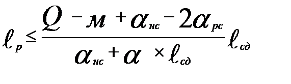
This value is close to the technical data of the equipment and cables. We find the permissible length of the regeneration of the area:
The second calculated ratio can be obtained by considering that the useful signal power at the input of the detector should not be less than the specified minimum permissible power
where The value is the name of the power equipment capacity and depends on the type of the selected light source and a photodetector:
The energy potential of taking passport data of the selected equipment. It is equal to = 31 The length of the maximum regeneration area defined by lines of weakening can be obtained from the relationship:
where
System margin takes into account changes in the composition of the optical cable due to the appearance of additional (repair) of inserts, welded joints, as well as changes caused by environmental exposure to optical cable characteristics of the environment and the deterioration of optical connectors, quality for life, and is set in the design FOTS on the basis of its destination operating conditions and service provider, in particular based on statistical damage (breaks) in the cable operator's service area. Recommended range of values set by the system reserve of 2 (the most favorable operating conditions) to 6 (worst-case operating conditions). These data are taken from the data sheet for the equipment [25]. Specifies the maximum length of the regeneration section, according to the formula (2.32):
Therefore, for single-mode fiber length depends on the regeneration site attenuation, but the calculation is performed with some margin, so more than in the technical specifications of the equipment manufacturer, which may be because the span calculation. It may not have been taken into account some parameters changed by the manufacturer in the design and manufacturing techniques that may be a trade secret, the use of cable with less attenuation. Length between OP-1 (Stepnogorsk) and OP-2 (Kokshetau) is 251, which exceeds the maximum = 98.4, therefore, must be installed on the cable line URP (SRP). Therefore, you must choose a location point of the regeneration that it satisfies the requirements of regeneration, and preferably located in the village, to ensure a constant supply of stationary equipment. In this case, it takes two regeneration points, to fit such requirements pos. Saule and g.Schuchinsk.
2.2 Digital transmission systems 2.2.1 The concept of building a modern transmission systems
The development of science and the acceleration of technological progress is not possible without improving communications, data collection, transmission and processing of information. Intensive development of new information technologies in recent years has led to the rapid development of microprocessor technology, which stimulated the development of digital transmission techniques. Ultimately, this led to the creation of new high-speed WAN technologies: PDH, SONET, SDH, ISDN, Frame Relay and ATM. One of the most advanced technology currently used for the construction of communication networks is the technology SDH synchronous digital hierarchy. Interest in the SDH due to the fact that this technology has replaced the PCM pulse code modulation (PCM) and plesiochronous digital hierarchy of PDH (PDH). Began actively implemented as a result of the mass installation of modern foreign digital PBX, allowing to operate with flows of 2 Mbit / s, and the creation of local regional SDH rings. Synchronous Digital Hierarchy (SDH) has significant advantages over previous generations of systems, it allows you to fully realize the potential of fiber-optic transmission lines and create flexible, easy to operate and control the network, ensuring high-quality communications. Thus, SDH concept allows optimally combine processes high-quality digital data transmission with automated management processes, control and network services in a single system. SDH systems provide transmission speeds of 155 Mbit / s and above, and can be transported as digital signals of existing systems (eg, common on city network of PCM-30), as well as promising new services, including broadband. SDH equipment is software-controlled and integrates the means of conversion, transmission, operational switching, control, control. With the advent of modern fiber-optic cables (FOC) made possible a high transmission rate in linear tract (RT) digital transmission systems with a simultaneous lengthening of the regeneration sections up to 100 km or more. Performance of LT exceeds the performance of digital paths in the cables with metal vapors 100 times or more that dramatically increases their cost-effectiveness. Most repeaters it is possible to combine with the terminal or transit stations. From this it follows that the SDH - is not just a new transmission system, this fundamental change in network architecture management. The introduction of SDH is a qualitatively new stage in the development of digital communication network. Therefore, the program of development of Kazakhstan in the long term the introduction of new information technologies belongs to one of the priority seats. Construction of fiber optic links in this area - the next logical step in the comprehensive modernization of communication of Kazakhstan, which will result in the creation of a powerful modern information network. Advantages of fiber optic to copper lines are clear: high reliability and noise immunity, large data transmission speed, large bandwidth. FOTS raises means of telecommunications to a new, much higher level of development. This reliable telephone service, Internet access and other global projects, the implementation of which is currently virtually impossible at this site. Introduction FOTS raise to a higher level and a secondary communication network, with a significant extension of new services which require broadband connections (e.g., network communication technology - video, video conferencing, industrial television, computer networks, operating in real time). The planned fiber-optic route is intended primarily to provide customers high-quality communications. Advantages of fiber optic to copper lines are clear: high reliability and noise immunity, large data transmission speed, large bandwidth. FOTS raises means of telecommunications to a new, much higher level of development. This reliable telephone service, Internet access and other global projects, the implementation of which is currently virtually impossible at this site. Introduction FOTS raise to a higher level and a secondary communication network, with a significant extension of new services which require broadband connections (e.g., network communication technology - video, video conferencing, industrial television, computer networks, operating in real time). The planned fiber-optic route is intended primarily to provide customers high-quality communications.
2.2.2 Transmission systems of PDH, characteristic features
In modern networks are operated as a plesiochronous system and synchronous digital hierarchy systems. Standard PDH - plesiochronous digital hierarchy. Hierarchy recommended for digital transmission systems, something like a calendar hierarchy. For this purpose it was necessary to select a certain unit of measure "e" bit rate common to all countries and companies that produce equipment of transmission systems and allows you to measure the speed of the total digital streams. This "unit" rate worldwide is digital speech transmission rate of 64 kbit / c. Channel on which are transmitted at 64,000 bits / s, is called the primary digital channel. Possibilities any digital transmission system estimates the number of organized with the help of just such standard channels. Combining flows leveling speed has been called plesiochronous (nearly synchronous), and the existing hierarchy of speeds transmission of digital streams, and hence the type of PCM transmission systems (PCM) - plesiochronous digital hierarchy (in the English writing Plesiohronous Digital Hierarhi, PDH). Plesiochronous digital hierarchy was developed in the early 80s. In the hierarchy of great hopes, but it was not very flexible in order to enter into the digital stream "rushing" at a high speed or low-speed output from it flows must be fully "embroider", and then "sew" high flow. This requires installation of a large number of multiplexers and de multiplexers. It is clear that to do this operation is often quite expensive. The system uses the principle of PDH plesiochronous multiplexing, according to which for multiplexing, for example, the 4-E1 (2048 kbit / s) into one stream E2 (8448 kbit / s) alignment procedure is performed such frequency signals occurring by stuffing. As a result, when multiplexing is necessary to make a step by step process of restoration of the original channels. For example, in the secondary digital telephone networks the most common use of E1. When sending this stream for PDH networks tract E3 must first perform incremental multiplexing E1-E2-E3-step demultiplexing and then E2-E3-E1 at each point E1 channel allocation. This is a major drawback PDH equipment - due to the increase in the number of necessary equipment for the separation of one or two streams. E1 primary digital channel DSO combines 32 channels, of which one DSO used for frame synchronization, another - for signaling. Still this stream consists of 32 time slots of 8 bits each. Frame repetition frequency 8 kHz, which gives the flow rate of 32 * 8 * 8 = 2048 kbit / s. The essence of the main drawbacks RDN is that the addition of equalizing bit makes it impossible to identify and output, for example, stream 64 Mbit / sec or 2 Mbit / s "hardwired" into the stream of 140 Mbit / s without complete demultiplexing or "embroidered" of this stream and removing leveling bit. One thing to "drive" the flow of long-distance or international calls from one call center to another "mixing" and "bark" them quite rare. Another thing - to connect several banks and / or their separation via PDH network. In the latter case often have to either output stream 64 kbit / s and 2 Mbit / s from the flow of 140 Mbit / s to make it, for example, a bank branch, or vice versa to output a stream of 64 kbit / s and 2 Mbit / s from the bank for putting it back into the flow of 140 Mbps, the implementation of such a step input \ conclusion have to spend quite a complex operation the three-level demultiplexing ("bark") PDH signal removing \ adding leveling bit (all three levels) and his subsequent three-level multiplexing ("stitching") adding new leveling bits. the alarm. However, these tools are too weak. If you have many users that require input \ output source (of 2 Mbit \ s) for the instrumental implementation of network flows require an excessively large number of multiplexers, as a result of operation of the network becomes economically advantageous. Another bottleneck technology PDH - weak capacity in the organization of channels for purposes of control and flow control in the network and the almost complete absence of routing funds grassroots multiplexed streams, which is essential for use in data networks. Typically, for the purposes of identification an
|
|||||||||
|
|
Последнее изменение этой страницы: 2016-08-01; просмотров: 101; Нарушение авторского права страницы; Мы поможем в написании вашей работы! infopedia.su Все материалы представленные на сайте исключительно с целью ознакомления читателями и не преследуют коммерческих целей или нарушение авторских прав. Обратная связь - 18.119.139.90 (0.017 с.) |


 (2.1)
(2.1)
 (2.2)
(2.2) - density of electric charge;
  and
and  - the electric and magnetic fields, respectively;
  - Current density;
  and
and  - the electric and magnetic induction.
 with the help of the Fourier transform [14]:
 (2.3)
(2.3) (2.4)
(2.4) - Laplace operator.
 , (2.5)
 (2.6)
(2.6) (2.7)
(2.7)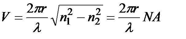 (2.8)
(2.8) (m = 1, 2, 3,..., n = 0, 1, 2, 3...):
 etc.
etc. (2.9)
(2.9)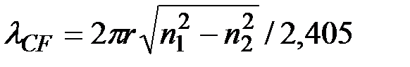 (2.10)
 (2.11)
 - the angle complementary to the angle of 90 i (or the angle between the beam and the axis as shown in Figure 2.4); β - it called constant propagation and plays the same role as the waveguide in the wave number k in free space so as
  , in accordance with the formula 2.11, i and
  wavelength dependent [16].
 varies between
  and π / 2. Consequently:
 (2.12)
 it is possible to rewrite this relation in terms of the phase velocity:
 (2.13)
 concluded between the phase velocity of the waves in the two bulk materials.
 , (2.14)
 , (2.15)
 , (2.16)
 = 2,3741.
 ×2a, (2.17)
 ×9 = 10,196 mcm.
 v in, is called the angle of total internal reflection:
 , (2.18)
 (2.19)
 (2.20)
 ) is an important section of the design. To provide a better quality of information transfer and saving of costs is preferable that
  , increases, the probability of error increases. Thus, the length of the regeneration area
  limited either attenuation or pulse broadening in line.
 (2.21)
 - the duration of the clock period PCM signal;
  - pulse duration;
  - the resultant dispersion or:
 (2.22)
 - the clock frequency of the signal line.
 (2.23)
 does not exceed half the length of the clock interval. These conditions determine the first estimated the ratio to determine the permissible length of the regeneration of the area:
 -
-  , (2.24)
 (2.25)
 - the resultant dispersion, as selected single-mode cable, the mode dispersion not consider. In singlemode optical fibers the resultant value is defined chromatic dispersion of the dispersion:
 (2.26)
 ) - material dispersion; (
 ) - Wave dispersion.
 (2.27)
 .
. =
= 

 ) - dependence of the propagation coefficient of the wavelength:
 (2.28)
 =
= 
 (2.29)


 , which provides a necessary reliability of signal transmission:

 - the power level of the radiation generator;
  ;
;  - loss of detachable connections
  (used to connect the receiver and the transmitter to the UK);
  ,
,  - losses at the input and output of radiation from fiber;
  ;
;  - loss of permanent connections;
  ;
;  - attenuation of the optical fiber;
  ;
;  - construction length OK.
 (2.31)
 .
. (2.32)
 - the average value plus 6
  - 0.5
- 0.5  - 0.1
- 0.1  - 4 km; - (-36)