Заглавная страница Избранные статьи Случайная статья Познавательные статьи Новые добавления Обратная связь FAQ Написать работу КАТЕГОРИИ: ТОП 10 на сайте Приготовление дезинфицирующих растворов различной концентрацииТехника нижней прямой подачи мяча. Франко-прусская война (причины и последствия) Организация работы процедурного кабинета Смысловое и механическое запоминание, их место и роль в усвоении знаний Коммуникативные барьеры и пути их преодоления Обработка изделий медицинского назначения многократного применения Образцы текста публицистического стиля Четыре типа изменения баланса Задачи с ответами для Всероссийской олимпиады по праву 
Мы поможем в написании ваших работ! ЗНАЕТЕ ЛИ ВЫ?
Влияние общества на человека
Приготовление дезинфицирующих растворов различной концентрации Практические работы по географии для 6 класса Организация работы процедурного кабинета Изменения в неживой природе осенью Уборка процедурного кабинета Сольфеджио. Все правила по сольфеджио Балочные системы. Определение реакций опор и моментов защемления |
The Synchronous Digital Hierarchy (SDH)Содержание книги Поиск на нашем сайте
The Synchronous Digital Hierarchy (SDH) Part 1 (42.1 –42.3) 1. Introduction 2. PDH deficiencies 3. The basis of SDH Introduction The Synchronous Digital Hierarchy (SDH) is a new standard for multiplexing together many low rate digital traffic channels into higher rate channels, in order that these low rate channels may be more efficiently transmitted around a telecommunications network. Viewed in this way, the SDH is merely a better alternative to the existing Plesiochronous Digital Hierarchy (PDH), which attempts to achieve more or less the same results. However, as we shall see later in this chapter, SDH has evolved to become much more than just the latest standard for combining and separating traffic channels. Due to the business pressures confronting the world's Public Telecommunications Operators (PTOs), SDH has developed into a comprehensive set of standards which address all aspects of a telecommunications transport network. The most important of these additional aspects concern the performance of traffic paths across the network, together with the automation of their management. The result of implementing the SDH standards is that a PTO now has a consistent mechanism for partitioning, monitoring and controlling the raw transport capacity of the whole network. Nevertheless, without some sound business drivers, most PTOs would view a move from the current, well proven, PDH to the more advanced SDH as, at best, an interesting academic exercise, and at worst, a scandalous extravagance. To see why there is such frenetic activity to changeover to SDH it is necessary to briefly examine the business environment in which the world's more advanced PTOs are now operating. The source of the problem is the PTOs' business customers. These are the customers from whom the PTOs derive a disproportionately large percentage of their profits, and who are becoming increasingly dependent on telecomms services for their very survival. Not surprisingly, business customers are looking to their use of telecomms to give them a competitive edge and thus, in addition to a straight reduction in tariffs, they are now demanding other things such as lower error rates and higher availability on their existing services, together with the bandwidth flexibility (i.e. channel capacity and routing capability) that enables the introduction of completely new services. In the past most PTOs operated as monopoly suppliers, and to some extent they could afford to resist these demands. Now, however, liberalisation and deregulation have introduced significant competition into several of these former monopoly markets, especially in the USA, UK and Japan. This competition to supply high quality telecom services to business customers is forcing PTOs to re-examine the cost effectiveness of their existing transmission networks. In particular, they are looking to balance the quality of service delivered to their customers against the capital and operating costs of their networks. The objective of this balance is, of course, to maintain or increase profits The disturbing conclusion of most PTOs is that it is not possible to deliver the quality of service demanded by business customers, at the right price, if they continue to operate transmission networks based on the current PDH. Even more disturbing is the fact that this conclusion was reached with full awareness of the falling costs of raw bandwidth i.e. the effects of reduced costs for optical fibres, electro-optic devices and the Application Specific Integrated Circuits (ASICs), which are the heart of any piece of transmission hardware. PDH deficiencies In order to fully appreciate SDH, it is useful to briefly examine some of the limitations of the PDH. These limitations fall under three main headings: 1 Lack of flexibility.It is more difficult, using PDH based equipment, to drop and insert a low rate channel from a high rate channel, without the use of a 'multiplexer mountain'. The normal example given is that of dropping out a 2Mbit/s channel from a passing 140Mbit/s stream. (See Figure 42.1.) The cause of this particular problem lies in the amount of information processing necessary to locate and extract the required traffic channel. The basic PDH multiplexing process involves a bit interleaving operation which obscures knowledge of the individual byte boundaries, and thus leads to an inflexible system This inflexibility extends beyond drop and insert functionality, to crossconnects. These become rather large and cumbersome because the PDH restricts them to use only space switching, as opposed to the much more efficient Time-Space-Time techniques that SDH allows.
Figure 42.1 The difficulty of accessing a passing 2Mbit/s stream using PDH equipment
2 Lack of performance. The PDH does not currently have any internationally standardised ways of monitoring the performance of traffic channels at 8Mbits and above. Even at 2Mbit/s, where there is a mechanism (CRC4), it only works when the 2Mbit/s channel has a G.704 frame structure imposed on it. Furthermore, the PDH does not have any agreed management channels or protocol stacks etc. Although some of the spare bits in the frame alignment words can be, and already are, used to carry management information, the information capacity is somewhat limited (e.g.22kbit/s @ 34Mbit/s). Worse still, when operating at one of the higher order rates, the PDH makes it difficult to retrieve any management information associated with lower order channels, without a full demultiplexing operation. Finally, even at 2Mbit/s, there is no guarantee of any management information. The usual example here is that of the 2Mbit/s private circuit, leased to the customer as a clear channel i.e. the PTO imposes no G.704 frame structure and the customer has full control over the entire 2.048Mbit/s bandwidth. In this case, there is no room for the PTO to insert any monitoring or control information, hence it cannot tell when the performance of such a circuit drops out of specification. On the other hand, the customer has almost certainly imposed his own frame structure, and therefore can monitor the delivered performance with great accuracy. 3 Lack of 'Mid-Fibre Meet'. Although the PDH specifies the exact format of the bit stream at the aggregate port of any PDH multiplexer, it puts no such constraints on the hit stream on the line side of a line transmission terminal. (See Figure 42.2.) Consequently, every manufacturer has used his own proprietary line code and optical interface specification, making it impossible for a PTO to interconnect line terminals from two different manufacturers. This operational constraint is destined to because an increasing problem due to the progressive fragmentation of the erstwhile monopoly transmission networks into a patchwork of smaller operations, all of which need to interwork with each other. Without an agreed Mid-Fibre Meet standard, this interworking becomes rather clumsy, as both ends of an interconnecting line system have to be bought from the same manufacturer, and will probably need to be controlled as a pair, rather than independently by each operator. It is interesting to note that Mid-Fibre Meet was one of the original targets for the SDH standard, when it was first proposed in the US as part of the early work on SONET, back in 1984. (SONET, Synchronous Optical network, is the North American counterpart to SDH. It preceded SDH by some years.) Of the above three problem areas, it is reasonable to suppose that (3) and to some extent (2) could have been solved by extensions and modifications to the existing PDH standards. In the future, though, it is likely that the sheer quantity of management information needing to be transported around a network, will eventually pose an insoluble problem for even a modified/extended PDH, hence any solution to this problem would always be viewed as a stopgap measure. The problem of traffic path inflexibility is much more difficult to overcome by modifying the PDH. It is tempting to suggest synchronising an entire PDH transmission network, as many PTOs have already done at the 2Mbit/s level. Unfortunately, as well as being progressively more difficult to do at the higher bit rates in the PDH, synchronisation alone does nothing to preserve the byte boundaries within each bit stream. Without any easy method of identifying these byte boundaries, the task of extracting both low order traffic and management channels has not been significantly simplified. As a final nail in the coffin, strict network synchronisation also entails the addition of 'wander' buffers at every multiplexer, in order to accommodate slow variations in the inherent delay of the transmission media (usually optical fibres these days). These buffers themselves give rise to further undesirable transmission delays, which could push some PTOs towards the otherwise unnecessary adoption of costly echo cancellers on 64kbit/s circuits throughout their networks.
Figure 42.2 Comparison of interfaces needed in PDH and SDH environments: (a) current PDH; (b) SDH
Figure 42.3 The basis of SDH frame structure
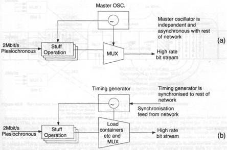
The basis of SDH Before investigating the SDH standards in detail, it is worth pausing for an overview of what SDH is designed to achieve, and the general way it goes about this task. As with PDH, SDH is designed to transport isochronous traffic channels and is focused very much on layer one of the well known ISO seven layer OSI protocol hierarchy. Again, like PDH, SDH is based on a hierarchy of continuously repeating, fixed length frames. This contrasts with the majority of competing standards, almost all of which attempt to deliver more efficient use of both transmission and switching plant by employing some form of packetisation of the transported information. Usually, these packets are launched into the network asynchronously and arrive at their destinations with a non-deterministic delay. Consequently, they present something of a problem to delay sensitive voice circuits, which still constitute 80% of all traffic, in even the world's most advanced networks. SDH, on the other hand, was formulated on the premise that despite the pressure to support novel forms of business oriented services, it is of paramount importance to preserve a smooth interworking with the existing PDH networks, most of which were designed to serve the PSTN above all else. At the same time, it was also apparent that the increasingly widespread deployment of optical fibres would rapidly reduce the cost of raw transmission bandwidth, hence there was relatively little pressure to restrict the proportion of bandwidth devoted to multiplexing overheads, as opposed to the traffic pay-load. Beyond the transport of isochronous traffic channels, and smooth interworking with the existing PDH, the developers of SDH also addressed those weaknesses of the PDH that were identified above. They recognised that it was necessary to adopt not only a synchronous frame structure, but one which also preserved the byte boundaries in the various traffic bit-streams. The basic SDH frame structure is one that repeats at intervals of 125μs i.e. it is tailor made for the transport of 64khit/s channels, or any higher rate channels which are an integer multiple of 64khit/s. (See Figure 42.3.) In fact, with one rather important exception dealt with in Section 42.4, SDH currently focuses on the transport of 2.048Mbit/s, 34Mbit/s and 140Mbit/s circuits, plus their North American counterparts at 1.5Mbit/s, 6Mbit/s and 45Mbit/s. The general way that any of these PDH rate circuits are transported by SDH is to map such a circuit into a "Synchronous Container". (See Figure 42.4.) A Synchronous Container can be viewed as a subdivision of the basic SDH frame structure, and it consists of a predefined number of 64kbit/s channels. The entire family of Synchronous Containers comprises only a few different types, each of which has been sized to accommodate one or more of the common plesiochronous transmission rates, without wasting too much bandwidth. The operation of mapping a plesiochronous circuit into such a Synchronous Container is very similar to the normal stuffing operation performed in a conventional PDH multiplexer. However, in this case, the plesiochronous channel is being synchronised not to the master oscillator in a PDH multiplexer, but to the frequency of the Synchronous Container, which is, in turn, synchronous to the basic SDH frame structure. (See Figure 42.5.) Before examining the question of exactly what the SDH frame structure is synchronous with, it is worth digressing to discuss a further operation specified by SDH. This is the attachment of an Overhead, known as the Path Overhead (POH), to each Synchronous Container (See Figure 42.4.) The idea is that once a plesiochronous circuit has been loaded into a Synchronous Container, this Container has a defined set of POH bytes appended to it, which remain completely unchanged until the Synchronous Container arrives at its destination. The combination of Synchronous Container plus POH is known as a Virtual Container (VC). The VC POH bytes allow a PTO to monitor several parameters, the most important of which is the error rate of the VC between the points at which it was loaded and unloaded with its plesiochronous payload. This provides a PTO with the much sought after end to end performance monitoring that was so difficult using conventional PDH techniques. Most plesiochronous channels are bi-directional, hence there are usually two continuous streams of VCs travelling in opposite directions between the two end points at which the plesiochronous channel enters and leaves the SDH portion of a network. Viewed in this way, the job of an SDH based network is to load its VCs with (usually) convention PDH channels, and then transport these to their various destinations together with an accurate indication of the quality of the delivered VC payload.
Figure 42.4 Example of the creation of a VC
This process of loading containers and then attaching POHs is repeated at several levels in SDH, resulting in the nesting of smaller VCs within larger ones. (See Figure 42.6.) The nesting hierarchy stops when the largest level of VC is loaded into the payload area of a Synchronous Transport Module (STM). These logical STM signals are seen at the interlace between any two pieces of SDH equipment, where they can be presented either electrically or, more usually, optically. (See Fig 42.2.) Such an interface is referred to as a Network Node Interface (NNI), because it is usually confined to the internal interfaces within the network, rather than any interlace presented to a network user. A User Network Interface (UNI) has also been defined, however, the way in which the payload information in a UNI is mapped into a standard NNI signal is not yet completely defined, and hence it is not widely used. Finally, the reason for the name Virtual Container is that unlike the STM signals that appear at the NNI, VC signals are never presented to the outside world. They exist only within pieces of SDH equipment or within STM signals, hence an SDH network element can have NNI and PDH interfaces, but never VC interfaces. Returning to the question of exactly what is synchronised to what, the basic problem is that, as outlined in Section 42.2, it is very difficult to maintain a complete transmission network in rigid synchronisation for all time. Even if we could tolerate the delays introduced by the addition of the numerous "wander buffers" necessary to accommodate the slow changes in transmission medium delay, there is no guarantee that different PTOs' networks would all be synchronised to the same master clock. For a network based on the SDH, this problem translates to that of how to synchronously multiplex and demultiplex many individual VCs, which, because they have been created in disparate parts of the same, or even different SDH networks, may have slightly different short term bit rates. The concept of pointers The solution adopted by SDH is to associate a pointer with each VC so that when it is multiplexed, along with others, into a larger VC, its phase offset in bytes can he identified relative to some reference point in this larger VC. (See Figure 42.7.) Furthermore, there is also a mechanism for allowing the value of this pointer to change if, for some reason, there is a loss of synchronisation, and the smaller capacity VC is running either slightly slower, or slightly faster than the larger VC. In fact, each of the smaller capacity VCs has its own pointer, which can change independently of any of the others. Although the use of these pointers still entails some input buffers, these are very much smaller than would be required if there were no mechanism for changing the phase of a small capacity VC within a larger one, hence the problem of excessive delays can be contained. We now have a picture of an SDH network as one in which the majority of VCs, both large and small, are well synchronised to each other, but, at the same time, there are a few which are not so well synchronised, and every so often, the increasing strain of their asynchronism has to be relieved by a byte sized slip relative to the majority of the other VCs in the network. Nevertheless, we retain our ability to locale the management and control information in the VCs POH bytes, because the pointer value associated with VC is recalculated whenever a slip occurs. The pointer mechanism described above is at the very heart of the SDH standard. It is this mechanism that enables us to construct networks that are nearly, hut not completely synchronous, and yet still allows us to easily locate each traffic channel (VC), together with its associated management and control information i.e. POH, but without incurring large penalties in transmission delay. It could be argued that SDH networks are not really synchronous at all, but are actually very tightly controlled asynchronous networks. However, the fact that we have quantised the slips due to this asynchronism means that it is now possible, at any time, to locate and route any of the traffic paths within an SDH network. This, together with network management software, gives us the traffic routing flexibility that was very difficult to achieve using PDH based equipment. In terms of actual network hardware, it opens the way to the production of economically viable drop and insert multiplexers and cross connects.
Figure 42.5 Difference in synchronisation between PDH and SDH: (a) PDH; (b) SDH
Figure 42.6 General representation of a 3 layer synchronous multiplexer structure
Figure 42.7 Pointers allow small VC to have arbitrary phase with respect to large VC
Exerise 1. Learn the following technical words and word-combinations:
42.1
42.2
42.3
Exercise 2 Read the text 42.1- 42.3
Exercise 3 Find the Russian equivalents for the following English technical word-combinations:
Exercise 4 Find the English equivalents for the following Russian technical word-combinations:
Exercise 5 Answer the following questions: 1. What does the Synchronous Digital Hierarchy mean? 2. What has the SDH developed into due to the business pressures confronting the world’s Public Telecommunications Operators (PTOs)? 3.What is the result of implementing the SDH standards? 4.Why is there such a frenetic activity to changeover from PDH to SDH? 5.Is it possible for PTOs to deliver the quality of service demanded by business customers if they continue to operate transmission networks based on the current PDH? 6.What are the three main limitations of the PDH? 7.Which of the three main problem areas of PDH could have been solved and in what way? 8.Does PDH have currently any agreed management channels or protocol stacks? 9.Why is it difficult to overcome the problem of traffic path inflexibility? 10. What is SDH designed for and what is it based on? 11. What is the basic SDH frame structure? 12. How can a Synchronous Container be viewed? What does it consist of? 13.What is the plesiochronous channel synchronized to? 14.What does the Virtual Container allow PTOs to monitor? 15.What does the SDH perform?
Exercise 6 a) Translate into Russian in writing part 42.3 paragraphs 4,5 (starting with “Before examining the questions… “) b) Translate into Russian in writing part 42.3 paragraphs 6,7 (starting with “This process of loading… “)
Exercise 7 Make a short report on the basis of SDH.
Part 2 (42.3.1-42.4.2) 1. The concept of pointers 2. The SDH standards 3. Path OverHead information 4. Multiplexing of Virtual Containers
The SDH standards There are now a dozen or more CCITT recommendations describing various aspects of SDH, but the centre-piece of the whole group is undoubtedly CCITT G.707/8/9. These three standards define the SDH multiplexing structure and the ways that non SDH traffic channels can be mapped into the SDH Virtual Containers. Other standards in the group deal with such things as the functionality of multiplexers (G.781/2/3), the management requirements of such equipment (G.784), and the equivalent recommendations for line systems (G.958). Optical interfaces for all types of SDH equipment are covered in G.957. Further standards (G.sdxcl/2/3, still in the draft stages) address the functionality of synchronous cross connects. Finally there are two more standards (G.snal/2), which address the way that entire SDH based networks should be constructed in order that they can interwork successfully with other such networks and, even more importantly, so that the management of these networks can be brought under software control. Nevertheless, because of their central role in SDH, we shall concentrate mainly on explaining G.707/8 & 9. Bearing in mind the nesting of smaller VCs within larger ones, and thence into STMs, the best way to appreciate the details of the SDH multiplexing standards G707/8/9, is to follow the progress of a hi-directional 2Mbit/s plesiochronous circuit, which, for part of its journey, is transported across an SDH based network. (See Figure 42.8.) Such a 2Mbit/s circuit could be a channel between two PSTN switches, or it could be a private leased line which is connecting two PBXs. Although the 2Mbit/s circuit is bi-directional, the SDH operations are identical in both directions, hence we shall concentrate on just one direction of transmission, that from A to D. At point B, where the 2Mbit/s circuit meets the SDH network, the first operation is to take the incoming plesiochronous hit stream and selectively add 'stuffing' bits in order to 'pad-out' this hit stream to the exact rate required to till the appropriate Synchronous Container. In this case, the Synchronous Container size would be a C12, which is sufficiently large to accommodate a 2Mbit/s plesiochronous bit stream at the limits of its 50 ppm tolerance, together with some additional 'fixed stuffing' bytes. The stuffing of the plesiochronous bit stream should ideally be done relative to the clock to which the whole SDH network is beating, however, as discussed in Section 42.3, there is a chance that the SDH network element (e.g. multiplexer) which is performing the stuffing operation, is not quite synchronous with the rest of the network. In this case C12 which it creates is similarly asynchronous.
Figure 42.8 2Mbit/s plesiochronous circuit from A to D, which is transported by an SDH network for part of its journey
Figure 42.9 Synchronous multiplexing of VC12s into a VC4 when VC12s are created in various places
Path OverHead information Having mapped the 2Mbil/s bit stream into the C12, the next operation is to generate and attach the Path Overhead byte (POH), which enables this C12 to be identified, monitored for errors and routed through the SDH network. The addition of this POH byte to the C12 creates a Virtual Container 12 (VC12). As mentioned in Section 42.3, the idea is that the POH stays attached to its C12 all the way from the point where it was generated, to the point at which the 2Mbit/s payload exits the SDH network. These two points are the 'Path Termination' points for this VCI2, with the continuous stream of VCs between them being referred to as the Path. Between the two path termination points at B and C, there is no legitimate mechanism for altering any of the information in the POH, hence if the receiving path termination detects any discrepancy between the POH and the content of the VC12 payload (i.e. the C12), this indicates that the VC12 payload has somehow become corrupted during its journey across the SDH network. Although path level monitoring is sufficient for a PTO to ascertain what error rate is being inflicted by the SDH network on his customers' 2Mbil/s circuit, it provides no information whatsoever on the source of the errors i.e. which network element has gone faulty. This task is dealt with by the addition of still further overhead information, which will he described shortly. Before this, it is necessary to examine the way in which several VC12s are multiplexed into a higher rate signal. Further use of Pointers The use of STMs and their associated SOHs entails a few additional complications beyond those discussed above. An STM may well be generated by a network element which did not have the privilege of also generating the particular VC4 that it is attempting to load. This immediately introduces the possibility of a slight asynchronism between STM and VC4, and, as with the VC12, this problem is also solved by a slip mechanism plus pointer. The pointer bytes occupy defined positions within the SOH and indicate the offset, in bytes, between themselves and the first byte of the VC4 POH. The main difference between this and the VC12 pointer is that when a VC4 slips its phase relative to the STM SOH, it does so by three bytes at a time, rather than the single byte phase change experienced by the VC12. A second difference between this case, and that of a VC12, is that the combination of a VC4 plus its pointer is known as an Administrative Unit 4 (AU4), rather than a TU4, when the pointer is located in an STM. The AU4 is used in all CEPTcountries as the size oftraffic block on which networks are planned and operated. There is also an AU3, which is used mainly in North America. This refers to an alternative construction of an STM, whereby the payload consists not of a single VC4, but instead, of a group of three VC3s, together with their associated pointers. A further difference between the STM SOH and a VC POH is that the SOH can be divided into two parts, known as the Multiplexer Section OverHead (MS OH) and the Regenerator Section OverHead (RSOH). (See Figure 42.12.). The reason for this is that on long line transmission systems the regenerators do not need to perform the rather costly, and in this case, unnecessary operation of generating and destroying the complete SOU. Instead, only a subset of a SOH is processed, leading to a reduction in gate count, power consumption etc., but still preserving the ability to detect traffic errors and access some management channels. On the other hand, the line terminal equipments process both the RSOHand MSOH. (See Figure 42.17.) Finally, as with VCs, STMs come in various sizes. As mentioned earlier, the smallest size is termed an STM-1, and can accommodate a single VC4. However, larger sizes exist whose hit rates are integer multiples of the basic STM-1 rate. CCITT G.707 currently recognises the STM-4 and STM-16, but STM-12 based network elements are also being designed, and it is likely that STM-64 will become a de facto standard in the near future. For all these higher rate STMs, the construction mechanism is the same: The payload is produced by straight byte interleaving of the tributary VC4s, while the SOH is constructed in a more complicated way, particularly in relation to the way the error checking bytes are calculated.
Figure 42.17 Line transmission system showing the multiplexer section overshea (MSOH) operating between LTEs, while only the regenerator section overhead (RSOH) is recalculated between each pair of regenerators
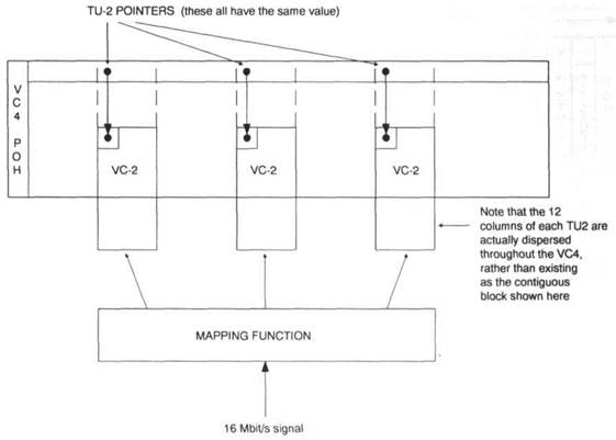
Figure 42.18 Loading of a hypothetical i6Mbit/s signal into 3 concatenated VC-2s (VC2 -3c) within a VC4
1. Learn the following technical words and word-combinations: 42.4.3
42.4.4
42.4.5
Exercise 2 Read the text 42.4.3- 42.4.5
Exercise 3 Find the Russian equivalents for the following English technical word- combinations:
Exercise 4 Find the English equivalents for the following Russian technical word- combinations:
Exercise 5 Answer the following questions: 1.In what way is it helpful to consider the internal structure of the VC4? 2.What is known as a Tributary Unit Group? 3.Is VC 12 the only size of Synchronous Container which has been defined? 4.Do Tributary Unit Groups constitute an extremely flexible mechanism for partitioning the payload bandwidth of a VC4? 5.What is VC 4 POH capable of? 6.How is the combination of the SOH (Section Overhead bytes) plus the VC 4 termed? 7.How can you appreciate the structure of a STM (Synchronous Transport Module)? 8.What is the standard representation of the smallest STM? 9.What is the significance of the STM SOH? What does the handling of the VC 4 include? 10.What happens after a network element receives an STM? 11.What is a powerful tool for locating the source of any poor performance within a network? 12.What can a slight asynchronism between STM and VC 4 introduce? How can this problem be solved? 13.What is the main difference between VC4 POH and VC 12 pointer?
Exercise 6 Make a short report on differences between VC POH and VC 12 pointer (part 42.4.5).
Exercise 7 a) Translate into Russian in writing part 42.4.3 paragraph 1. b) Translate into Russian in writing part 42.4.3 paragraphs 2,3 (up to “A TUG3 is one third…”).
Part 4(42.4.6-42.4.9) 1. Other sizes of VCs and payloads 2. SONET and SDH 3. NNI Optical Interface standardization 4. SDH network elements
SONET and SDH Several mentions have been made of SONET as being both the forerunner and the North American equivalent of SDH. The SONET standards were designed around the need for efficient transport of the existing North American PDH rates, the most important of which are the 1.5Mbit/s and 45Mbit/s rates. This leads toa standard where a 45Mbit/s signal is loaded into the equivalent of a VC3, which, in turn, is loaded into the SONET counterpart ofan STM, known as a Synchronous Transport Signal - I (STS-1), which runs at 51,84Mbit/s i.e. precisely one third of the STM-1 rate. As with SDH, there is also a concatenation mechanism for dealing with customer signals which do not easily lit inside any of the already defined VCpayload areas. This mechanism is particularly useful for carrying rates such as 140Mbit/s, where the concatenation results in a SONET NNI signal known as an STS-3c, which has a bit rate that is identical toan STM-1, and an SOH and payload area ofexactly the same size as well. Other terminology within SONET is also different, in that SONET refers to Virtual Tributaries (VTs) rather than VTs, and the equivalent of the VC3, referred to above, is known as a Synchronous Payload Envelope (SPE). It also makes a distinction between the STS logical signal and its optical manifestation at an NNI, in which case it is referred to as an Optical Carrier (OC). North American transmission systems are usually referred to by their transmissionrates in OCs e.g. OC3 or OC48. SDH network elements Because traffictouting flexibility is one of the reasons forthe existence of SDH, the simplest wayof considering any SDH network element is as a group of transporttermination functions (TTFs)surrounding a trafficpath connectivity function (see figure 42.21) The TTFs are essentially the conversion functions from the VC level to either the STM or plesiochronoussignal levels, while the connectivity function allows VCs to berouted between the various TTFs.More than anything else, it is the size and flexibility ofthe connectivity function that distinguishes one type of network element from another. For example, a crossconnect may have a large connectivity function, capable of simultaneously routing a large number of VCs of a given type between a large number of TTFs, with very few restrictions on this connectivity. This, of course, is consistent with the normal role of a crossconnect, as a major traffic routing node in a transport network, where electronically control-table traffic routing flexibility is its raison d'etre. At the other end ofthe scale come Line System Terminals (LTEs), which normally incorporate a multiplexer as well. The connectivity between tributaries and aggregate ports of such a multiplexer is normally hard wired, hence no flexibility whatsoever. Between these two extremes come drop and insert (Add/Drop) multiplexers, which attempt to strike a balance, that leads to adequate, rather than comprehensive routing flexibility, with an attendant reduction in equipment costs. All ofthe above mentioned types ofnetwork element normally assume that any interconnection will be based on optical fibres. It is, however, also possible to use other interconnection media, in particular radio transmission. The problem in using radio interconnectionis that, unlike optical fibres, the available spectrum is finite, and in short supply. The liberal use of overhead capacity in SDH only exacerbates the already difficult problem of squeezing the trafficinformation into the existing arrangement of radio channel bandwidths. These problems are by no means insuperable, but they do tend to restrict radio interconnection of NNI signals to the lower end ofthe SDH range e.g. up to STM-2 at present. This inability to match the transmission capacity ofoptical fibres will progressively force radio based systems out of the core areas of transmission networks, and into the more peripheral areas. In particular, it is likely that radio based SDH equipment will be heavily used for access duties The reduction in cost that accompanies a network element with restricted connectivity results not only from simpler hardware, but also from simpler control software. This is somewhat surprising at firstsight, as it has often been said that SDH does not really make economic sense without a large measure of software control over all the network element functionality and, in particular, that of routing flexibility.However, the complexity of even relatively simple SDH network elements leads to a situation where control of complete networksrapidly escalates unless some restrictions are put on the traffic routing complexity. In short, every additional piece of traffic routing flexibility is a potential network control headache. The general problem of control of a whole SDH network, notwithstanding the traffic routing problem, is almost impossible if it is composed of network elements from different manufacturers, which do not have some form of common control interface. Before we can arrive at such a universal interface, we must first standardise, to a large extent, on the functions which each of the network elements actually perform. This is where the network element functional standards, CCITT G.781/2/3, come in. These are the recommendations which describe how the functionality of a network element can be decomposed into the basic 'atomic' elements of functionality, together with how such atomic functions may be combined and thereafter exchange both traffic and control information. (See Figure 42.22.) The rules for combination of these atomic functions enable a variety of network elements to he synthesised, with differing traffic capacities and routing capabilities. Indeed, one of the current problems is the potentially large number of different ways a conformant network element can be constructed. It is rather difficult for software based control systems to cope with this variety and hence there are efforts in several standards fora (notably ETSI), to standardise on a more restricted range of network element functionalities. G.781/2/3 were created primarily to describe different types of drop and insert multiplexers, however, the general principles and indeed, much of the detail, are just as applicable to LTEs and large cross connects. Moreover, the formalism required to describe complete SDH networks was produced very much with this same functional decomposition in mind. We shall see, later, how these atomic functions may be paired between network elements on opposite sides of a network to produce a complete traffic path, that is sufficiently well defined for a computer to recognise.
Figure 42.21 Generalised representation of the traffic paths through an SDH network element
Figure 42.22 Fragment of an SDH network element showing how it is broken down into atomic functions acording to CCITT G.783
Figure 42.23 Network management layering for the control of telecoms networks and services
1. Learn the following technical words and word-combinations:
42.4.6
42.4.9
Exercise 2 Read the text 42.4.6- 42.4.9.
Exercise 3 Find the Russian equivalents for the following English technical word-combinations:
Exercise 4 Find the English equivalents for the following Russian technical word-combinations:
Exercise 5 Answer the following questions: 1.How have mappings into Synchronous Containers been defined so far? 2.What do CCITT G.708 and G.709 contain? 3.What signal is the only byte synchronous mapping defined for? 4.What is the advantage of the byte synchronous mapping? When does this mapping become apparent? 5.What were the SONET standards designed for? What new standard appeared later? 6.What other terminology exists within SONET? 7.What does the recommendation G.957 specify? 8.Why is there no guarantee of anything beyond traffic path interworking? 9.What is the simplest way of considering any SDH network element? 10.Is the size and flexibility of the connectivity function of great importance for distinguishing one type of network element from another? 11.Why is it likely that radio based SDH equipment will be used for access duties? Why? 12.Under what conditions is it impossible to control a whole SDH network?
Exercise 6 Make a short report on SDH network element (part 42.4.9).
Exercise 7 a) Translate into Russian in writing part 42.4.9 paragraph 1. b) Translate into Russian in writing part 42.4.9 paragraphs 2 (up to “The reduction in cost…”).
Part 5 (42.5- 42.6) 5. Control and management 1. SDH based networks
Control and management Control and management within any type of telecommunications network (not just an SDH one) can best be viewed in terms of a series of layers (See Figure 42.23). At the lowest level, there is internal control of an individual network element, which performs internal housekeeping functions and deals in alarm and control primitives. CCITT G.783 has rigorously defined a minimum set of control and alarm primitives for each of the SDH atomic functions, and these are the basis of all SDH management. However, beyond this CCITT G.784 describes how such primitive information should be processed and ordered to produce derived information such as error rates etc, which is stored in logs of defined duration, and reported at set intervals, etc. At the lowest level, some of this information may look rather different to that specified in G 783/4 etc, however, the internal network element control system takes these and from them, synthesises the information that is required by the next level in the management hierarchy i.e. the element manager. The element manager is a piece of software which can control many individual network elements (usually in the range 10-1000), but it can only control them as individual elements and does not have any view of the traffic relationships between them. Usually it is located remote from the elements it is controlling and more often than not, it runs on some form of workstation. The interface between the element manager and the network elements is an obvious area for standardisation, as without this there is little chance of a single element manager controlling network elements from more than one manufacturer. Despite the progress that has been made in rigorously describing the network element atomic functions, it has still proved very difficult to agree on a software description of them. The approach adopted in CCITT, ANSI, and ETSI has been to describe complete network elements as collections of 'objects' in line with the rules of 'object orientated' programming. The idea is that an object is a software entity that has both attributes and behaviour. External stimulate (i.e. information, commands, etc.) trigger an object to behave in a certain way e.g. change its attributes, transmit information, commands etc. The claim is that a standardised object could be looked upon as the software equivalent of a hardware integrated circuit. One of the biggest areas of disagreement in generating an agreed standard set of SDH objects, is the questions of whether an object should represent a pieceof functionality or whether an object should represent a (small) piece of hardware. Although CCITT G.783 functionally decomposes SDH equipment, its says almost nothing on the way such atomic functions are split or combined in any real hardware implementation. The current view within both CCITT and ETSI is that the set of objects (collectively known as the 'Information Model') should present both a functional and a physical view of the network element that they represent. ETSI, in particular, is making good progress in generating a model along these lines. Not only is it necessary to have a standardised information model, so that the network element and element manager can understand line another, it is also necessary to have an agreed message set to go with it. Fortunately, this flows reasonably easily from the definition of the objects themselves. However, the existence of such a message set, then leads to the requirement for an agreed information protocol stack with which to transport it. For information transferred between a network element direct to its element manager, CCITT G.773 details several allowed protocol stacks, which split into two groups, those which have a full 7 layer structure and those which have a 'short stack', where layers 4, 5, and 6 are absent. Most observers favour the use of the heavier, but more flexible, seven layer protocol stacks for SDH networks, while the 'short' stacks are more appropriate for PDH equipment for which it is more difficult to justify the burden of the additional layers. Not only are there defined protocol stacks for information transfer direct from element manager to network element, but there is also a defined protocol stack for information transfer between individual network elements. In general, the majority of information transfer between network elements is actually information arising from an element manager, which is being relayed by an intermediate network element to a more remote element. (See Figure 42.24). This flow of management information amongst network elements, element managers and yet more managers at the network and service levels, gives rise to the concept of a Telecommunicatioas Management Network (TMN). The main recommendation concerning the TMN is CCITT M.30, which attempts to define a series of interfaces between different management entities in such a network. It is not confined purely to SDH networks, but SDH networks will probably be the first to implement an M.30 style TMN. (See Chapter 16.)
Figure 42.24 Control channels and protocols within a SDH network
SDH based networks An SDH based network can be viewed as the transmission bedrock which supports all other terrestrial telecommunications services. (See Figure 42.25.) As already mentioned, the main advantages of such a network are the ease and precision with which the available network bandwidth can be partitioned amongst the higher layer services, together with accurate monitoring of the quality of the transmission links. Despite this, the control and management of complete networks of the size operated by BT, France Telecom, or DBP is a difficult problem, which requires some degree of standardisation in the way such networks are functionally decomposed, in much the same way as the individual network elements have already been functionally decomposed into their atomic elements by CCITT G.783. The basic idea behind the functional decomposition described in CCITT G.snal is that a transport network can be stratified into a number of layers. Each layer provides a service to the layer above it, and is, in turn, a client of the layer below it, in much the same way as the ISO seven layer information transfer model consists of layers which participate in client-server relationships with their vertical nearest neighbours. (See Figure 42.26.) This layering within an SDH network could be viewed as a subdivision of ISO layer 1. As an example of a non-SDH client-server relationship in a trans-port network, consider Figure 42.27, which shows a 64kbit/s circuit being a client of the 2Mbit/service layer i.e. the 2Mbit/s layer, which can be viewed as a 2Mbit/s network, transports the 64kbit/s circuit between its desired end points. In order to do this, the 2Mbit/s layer will probably call upon the services of the 8Mbit/s layer, and so on up to the 140Mbit/s layer. The SDH counterpart of this simple PDH example is slightly more complicated in that the transport layers are divided between those concerned with end to end networking (i.e. the Path Layers) and those concerned with transport between each pair of SDH network elements along the route (i.e. the SIM section layer). As an additional complication, there are two path layers, the lower order paths consisting of VC1 s, VC2s or VC3s, and the higher order paths, which are VC4s in CEPT countries, hut could also be VC3s. (See Figure 42.28.)
Figure 42.25 Managed transmission network; SDH network as a bearer for other services
Figure 42.26 Layering and client server relationships between the layers of an SDH network
Figure 42.27 64kbit/s circuit making use of a 2Mbit/s serv
|
||||||||||||||||||||||||||||||||||||||||||||||||||||||||||||||||||||||||||||||||||||||||||||||||||||||||||||||||||||||||||||||||||||||||||||||||||||||||||||||||||||||||||||||||||||||||||||||||||||||||||||||||||||||||||||||||||||||||||||||||||||||||||||||||||||||||||||||||||||||||||||||||||||||||||||||||||||||||||||||||||||||||||||||||||||||||||||||||||||||||||||||||||||||||||
|
|
Последнее изменение этой страницы: 2016-12-12; просмотров: 188; Нарушение авторского права страницы; Мы поможем в написании вашей работы! infopedia.su Все материалы представленные на сайте исключительно с целью ознакомления читателями и не преследуют коммерческих целей или нарушение авторских прав. Обратная связь - 18.119.118.151 (0.014 с.) |