Заглавная страница Избранные статьи Случайная статья Познавательные статьи Новые добавления Обратная связь FAQ Написать работу КАТЕГОРИИ: ТОП 10 на сайте Приготовление дезинфицирующих растворов различной концентрацииТехника нижней прямой подачи мяча. Франко-прусская война (причины и последствия) Организация работы процедурного кабинета Смысловое и механическое запоминание, их место и роль в усвоении знаний Коммуникативные барьеры и пути их преодоления Обработка изделий медицинского назначения многократного применения Образцы текста публицистического стиля Четыре типа изменения баланса Задачи с ответами для Всероссийской олимпиады по праву 
Мы поможем в написании ваших работ! ЗНАЕТЕ ЛИ ВЫ?
Влияние общества на человека
Приготовление дезинфицирующих растворов различной концентрации Практические работы по географии для 6 класса Организация работы процедурного кабинета Изменения в неживой природе осенью Уборка процедурного кабинета Сольфеджио. Все правила по сольфеджио Балочные системы. Определение реакций опор и моментов защемления |
Measuring of info signal frequency using digital methodСодержание книги
Поиск на нашем сайте
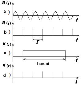
Currently, the digital method was the most common. On the basis of much of the built of frequency produced by industry. Typically, a digital frequency meter provides the ability to measure not only the frequency but also the period of repetition and time intervals. Some devices can measure and other parameters of signals and circuits, pre-converting them into a time interval or frequency. Thus, digital frequency meters are a good basis to build multipurpose devices. In particular, digital electronic frequency counters (DEFC), we can measure the frequency, the period of the signal, the ratio, difference, sum frequency, etc. The study is based on the principle of frequency digital discrete calculation: counting the number of pulses over a certain period of time, which has many advantages. These include a wide measuring range, high accuracy and robustness, the possibility of releasing the results of measurements on printing, etc. Frequency measurement is carried out by direct comparison of the frequency f s res of the signal with the value of the standard frequency f s ast created by a quartz oscillator, as a measure. The most optimal in terms of reducing the error measurement result, this mode will be provided if the measured frequency is much higher than the frequency of the signal model. In this mode, a periodic signal of frequency f s res is applied to a frequency input (Fig. 1). After the input device (1) study the signal goes through the switch (2) (key switch is in position 1) to the transmitter analog signal to digital (3). Here, the analyzed signal (for example sine wave) is transformed into a periodic sequence of short pulses (Fig. 2). The individual pulses of this sequence can be generated in moments of transition sinusoidal signal with a zero derivative of the same sign. Thus, the frequency of these pulses coincides with the frequency f s res of the measured signal. Furthermore, this sequence of pulses is fed to one input of a temporary selector (4). At the time the other input selector is applied, the so-called strobe pulse. Formation of strobe pulse occurs in the control channel, a model in which the voltage frequency generated by the crystal oscillator is fed through the switch (8) (key switch is in position 1) through a block of frequency division (9) sharper (10).
In Fig. 2 shows the stress distribution of DEFC that demonstrate the essence of the digital method, which is reduced to counting the number of pulses N, arriving at the counting unit (11) for a time equal to Т acc, titled "TIME MEASUREMENT" or "COUNTING TIME", i.e.
Where f sact – the actual value of the measured frequency. Thus, the frequency of the signal is determined by the expression:
where Т count = Т qg. Measuring the counting unit will go to the (N ± 1) due to the sampling pulse, then
where Т count = nТ qg; Т qg – the period of oscillation oscillator; n – frequency division ratio of the block (9).
Measuring the frequency with electronic frequency counter there are two error components: measures (due to instability of the frequency oscillator) and comparison (by sampling). In today's digital frequency crystal oscillators are used with relative frequency instability of the order of ± 10-10... 10-12. Accuracy is determined by comparing mainly discreteness error, that is due to the fact that the front and drop the control (strobe) pulse is not synchronized with the appearance of a periodic sequence of pulses, formed from the test signal, or, in other words, this error is associated with a multiple of the periods of measuring signal model. The maximum value of the absolute error of discreteness Δ N:
It does not depend on the frequency of the signal and is expressed in Hz. Reduce the value of the absolute error can be due to the increase of measurement time T acc. The minimum value of Δ N can be obtained at T calc due to the limits on the counting unit electro-counting frequency meters, that is
where q – the number of electronic frequency counter rank. Then, using (4)
The maximum value of the relative discrete error is given by
where N – the number of pulses received by the counting unit of electronic frequency counter. The total error in measuring the frequency
where δqg – component of the error, introduced by the measure (crystal oscillator).. Position the decimal point is determined by measuring the degree of a series of numbers expressing the measurement time Т count in milliseconds, which implies a measurement of frequency, "kHz", as specified in the display frequency. This series of numbers is as follows: Т count = (100; 101; 102; 103; 104) ms. After calculating the Т calc is selected from the specified number of Т count, adhering to the following conditions: - if Т calc ≥ 104 ms, then we can take Т count = 104ms; - if 104ms> Т calc > 103ms, then choose Т count = 103 ms and so on. The result is displayed electronic frequency counter, as mentioned is in kHz.. Example. Frequency of the signal is 650 kHz. The measurement is carried out by electronic frequency counter of Ч3-57 type. Its main metrological characteristics (МC): - a range of measuring frequency of 0,1 GHz ÷ 100 МHz; - period measurement range 1mcs ÷ 104ms; - counting time 100 ÷ 104 ms; - period factor 100 ÷ 104; - time markings 0,1 µs; 1 µs; 0,01 ms; 0,1 ms; 1 ms; - digits number – 7. You must define: Т count, Δ N and δ N and record the measurement result. Solution. We define:
Based on the above recommendations, select Т count = 104 ms = 10 s. Absolute accuracy:
Discrete ratio error:
Where f с – in Hz; Т count– per second. The result on the display is 650,0000 kHz.
Measuring low-frequency error of discreteness is the defining component of measurement error. For example, if the measured frequency f s res = 5 Hz at Т count = 1 s, maximum value of absolute discrete error Δ N = ± 1 Hz, and the maximum value of ratio error Thus, because of the large discrete low-frequency error is directly measured by a digital frequency meter with a low accuracy. Therefore, finding ways to reduce the influence of the discreteness error in the measurement result has always been one of the important directions of development of digital frequency-measurement technology. The first way is obvious: it is to increase the duration of the "gate time", that is the duration of the measurement time. But the possibilities of this method is limited because conventional digital frequency counter (non-microprocessor), the maximum possible duration of the measurement time Т count = 10 s. The second way is to increase the number of pulses that fill "time-gate", which is achieved by multiplying the frequency of the signal. The maximum absolute error does not change (if not change the duration of "time-gate"), but decreases the relative error (in the number of times of multiplication). The implementation of this method involves the use of additional power - frequency multiplier, which makes it difficult and expensive equipment. The third method, which takes into account the random nature of the error of discreteness, implies a multiple of observations (individual measurements) and averaging the results. This is an effective way to reduce the influence of random error in the measurement result. The fourth method is direct measurement of the period of the signal and then calculating the numerical values of the frequency (f s = 1/ Т сount), the inverse result of the measurement period. This path can dramatically reduce the error in the measurement of discrete low frequencies.
Measuring the time interval (period) of info signal
In this mode, the comparison of the researched signal measured period Т s model with a time interval. The signal is going to the input 2 electronic frequency counter (Figure. 1, key is in position 2) and then after appropriate transformations in blocks (7) (8) and (9) via a control unit (10) is fed to the second input selector (4). In block (10) of the test signal is formed by a rectangular gate pulse, the duration of which coincides with the period of the signal or a multiple thereof. The voltage from the standard frequency crystal oscillator (5) through a frequency multiplier (6), switch (2) (the position of key switch - "2"), the inverter (3) and then fed to a first input selector of the time. Stress diagram illustrating the operation mode of electronic frequency counter meter measurement period are shown in Figure 3. They show that the period of the signal is given by:
where Т m – the period of the signal model (time of marking); N – number of marks received by the counting unit electronic frequency counter; n – the factor period (for the given case is n = 1).
Calculation time is given by:
The result is displayed on electronic frequency counter, usually represented in units of the selected "mark time" (ms or µs). The situation with the decimal point depends on the value of the multiplier period, and the numerical values of the period of temporary tags. Accuracy of measurement period Т s act consists of three components: the error of measure, conversion and comparison. The error measure is due to the relative instability of the crystal frequency δqg = 5·(10-8÷10-12). The error is caused by the transformation δt mainly the ratio of the voltage signal and noise that affects the formation of the control pulse and is determined from the expression (Simpson's formula):
where n – number of periods of the measured signal; U n – the average value of the voltage noise; U s – the average value of the voltage signal. If The error is caused by an error of discrete comparisons. Absolute and relative error respectively,
The total relative error is given by:
To select the best performance in terms of minimizing the error, we consider the following example.
Example. Let the measured signal frequency is ƒ s res = 100 Hz, (Т сount = 10-2 s), by the same frequency meter. To define: ∆ N, δ N, to choose n, T m and record the measurement result. Solution. Choose the timestamps (usually a minimum value), Т m = 0,1µs = 10-7 s. Given the limitations on the counting value of the multiplier block of n signal period:
Since 10 < n <102, then the multiplier period take n = 10. Write down the measurement period on the display: 10000, 00 µs. Absolute error
Relative error
where
|
||||||||||||||||||||||||||||||||||||||||||||||||||||||||||||||||||||||
|
|
Последнее изменение этой страницы: 2016-09-19; просмотров: 480; Нарушение авторского права страницы; Мы поможем в написании вашей работы! infopedia.su Все материалы представленные на сайте исключительно с целью ознакомления читателями и не преследуют коммерческих целей или нарушение авторских прав. Обратная связь - 18.117.105.184 (0.008 с.) |


 ,
,


 .
.
 ,
,
 ,
,
 ,
,
 .
.
 Hz.
Hz.
 .
.
 , that is 20%, which is unacceptably high.
 ,
,

 ,
,
 = – 40 dB and п = 1, then δt ≈ 0,3%, if n = 100, then δt = 0,003%.
 ,
,
 .
.
 =
=  .
.
 <102.
<102.

 ,
,
 ,
,  .
.