Заглавная страница Избранные статьи Случайная статья Познавательные статьи Новые добавления Обратная связь FAQ Написать работу КАТЕГОРИИ: ТОП 10 на сайте Приготовление дезинфицирующих растворов различной концентрацииТехника нижней прямой подачи мяча. Франко-прусская война (причины и последствия) Организация работы процедурного кабинета Смысловое и механическое запоминание, их место и роль в усвоении знаний Коммуникативные барьеры и пути их преодоления Обработка изделий медицинского назначения многократного применения Образцы текста публицистического стиля Четыре типа изменения баланса Задачи с ответами для Всероссийской олимпиады по праву 
Мы поможем в написании ваших работ! ЗНАЕТЕ ЛИ ВЫ?
Влияние общества на человека
Приготовление дезинфицирующих растворов различной концентрации Практические работы по географии для 6 класса Организация работы процедурного кабинета Изменения в неживой природе осенью Уборка процедурного кабинета Сольфеджио. Все правила по сольфеджио Балочные системы. Определение реакций опор и моментов защемления |
Heli-specific advance menu functionsСодержание книги Поиск на нашем сайте
5.3.1 THR-CURVE and PIT-CURVE: These 7-point curves are utilized to best match the blade collective pitch to the engine RPM for consistent load on the engine. Curves are separately adjustable for normal, idle-up 1, idle-up 2, and idle-up 3. In addition, a separate collective pitch curve is available for throttle hold. Sample curves are displayed in the appropriate setup types (ex: normal flight condition) for clarity. Suggested defaults: • Normal: Collective pitch curve that results in points 1, 4 and 7 providing.4, +5, (+8 to +10)* degrees pitch. A throttle curve setting of 0, 25, 36, 50, 62.5, 75, 100%. • Idle-ups 1 & 2: Idle-ups 1 and 2 are typically the same except for the gyro settings, with one being heading-hold/AVCS and the other being normal mode. The pitch curve will likely be similar to the normal curve above. • Idle-up 3: Collective pitch curve that results in points 1, 4 and 7 providing (.8 to.10), 0, (+8 to +10) degrees. A throttle curve of 100, 75, 62.5, 50, 62.5, 75, 100 provide full throttle for inverted maneuvers. • Throttle Hold pitch curve: Start with the normal pitch curve (for inverted autos, start from the idle-up 3 pitch curve), but increase the last point approximately 1-2Ўг, if available, to ensure sufficient pitch at landing. This default recommendation assumes you are doing forward flight. If you are just learning, please follow your instructor's guidance. Some instructors like a +1 base point for training so that the helicopter comes down very slowly, even if your instincts pull the throttle/collective stick to the bottom in a hurry. ADJUSTABILITY: • Normal condition curves are editable in the BASIC menu for convenience. • All curves may be adjusted in the ADVANCE menu. • Automatically selected with the proper condition. • The idle-up curves are programmed to maintain constant RPM even when the collective pitch is reduced during flight (including inverted). • To change which conditionЎЇs curve is being edited, cursor up to <COND> and change the curve named. • For clarity, the name of the condition currently active (switched on in the radio) is shown in parentheses behind name of condition whose curve is being edited. (Example: see curve displays below. Note that the normal condition is active but the idle-up 1 conditionЎЇs curves are currently being edited. • Moving and deleting the curve point: The curve point (-stk-) can be moved to the left or right by turning the DIAL (up to 2% in front of the adjoining point) and deleted/returned by pressing the DIAL for one second alternately. • Idle-ups and throttle hold pitch curves may be edited even before the conditions have been made active. Activating their throttle curves activates these conditions.
5.3.2 REVO MIX: This 5-point curve mix adds opposite rudder input to counteract the changes in torque when the speed and collective pitch of the blades is changed. ADJUSTABILITY: • Three separate curves available: normal for hovering; idle-ups 1 and 2 combined; and idle-3. • Normal condition curves are editable in the BASIC menu for convenience. • All curves may be adjusted in the ADVANCE menu. • Correct mix is automatically selected in-flight with each condition and automatically activated when the throttle setup for that condition is activated in the programming (i.e. THROTTLE HOLD or THR-CURVE.) • To change which conditionЎЇs curve is being edited, cursor up above POINT5 and select. For clarity, the name of the condition currently active (switched on at the radio) is shown in parentheses behind the name of the condition whose curve is being edited. Revo. Mixing rates are 5-point curves. For a clockwise-turning rotor, the rudder is mixed in the clockwise direction when collective pitch is increased; for counterclockwise-turning, the opposite. Change the operating direction setting by changing the signs of the numbers in the curve from plus (+) to minus (-) and vice versa.
Suggested defaults: Clockwise rotation: -20, -10, 0, +10, +20% from low throttle to high. Counterclockwise rotation: +20, +10, 0, -10, -20% from low throttle to high. Adjust to the actual values that work best for your model. Revo. Curves for idle-ups are often v-shaped to provide proper rudder input with negative pitch and increased throttle during inverted flight.(Rudder is needed to counter the reaction whenever there is increased torque. In inverted flight, throttle stick below half has increased throttle and negative pitch, therefore increasing torque and rotating the helicopter unless the revo. Mix is also increasing appropriately.)
• THR-CURV/NOR: inputs the normal (NORM) throttle curve, which is usually not a linear response to THROTTLE STICK motion. Adjusting point 4 of the curve adjusts the engine's RPM at the THROTTLE STICK midpoint, the desired position for hovering. The other 6 points are then adjusted to create the desired idle and maximum engine speed, and a smooth transition in-between. • PIT-CURV/NOR: inputs the normal (NORM) collective pitch curve, the collective pitch curve for flight near hover. The normal collective pitch curve is adjusted to match the throttle curve, providing the best vertical performance at a constant engine speed, with a starting curve of 4 base, +5 neutral, and +8 to +10 degrees of blade pitch maximum. You can program the response over a 7-point curve for the best collective pitch angle relative to THROTTLE STICK movement. • REVO./NORM: mixes collective pitch commands to the rudder (a PITCH-RUDDER mix) to suppress the torque generated by changes in the main rotor's collective pitch angle, keeping the model from yawing when throttle is applied.
GYRO SENSE About GYRO SENSE, please refer to 3.3.12, by following steps:
THROTTLE HOLD This function holds the engine in the idling position and disengages it from the THROTTLE STICK when SWITCH AT9 is moved. It is commonly used to practice auto-rotation. Prior to setting up THR-HOLD, hook up the throttle linkage so that the carburetor is opened fully at high throttle, then use the digital trim to adjust the engine idle position. To have THR- HOLD maintain idle, move the THROTTLE STICK to the idle position, then move the hold SWITCH on and off and keep changing the offset value until the servo does not move. To lower the engine idle speed, or if you want to shut off, input a more negative number. ADJUSTABILITY: • Idling position: Range of -50% to +50% centered about the throttle idle position to get the desired engine RPM. • Switch assignment: Assigned to SWITCH E(AT10) or G (AT10) down. Adjustable in the CONDITION (THR-HOLD item), (2-position type switch only) • Throttle curve: Since the throttle is moved to a single preset position, no curve is available for THR-HOLD. • Collective pitch curve: Independent curve, typically adjusted to create a blade pitch range of -4% to +10% to +12%, is automatically activated with THRHOLD. • Revo. mix: Since revo. mix adjusts for torque from the engine, no revo. mix is available for THR-HOLD. • Priority: The throttle hold function has priority over idle-up. Be sure that the throttle hold and idle-up SWITCHES are in the desired positions before trying to start the engine. (We recommend starting your engine in throttle hold for safety reasons.) • Gyro: Gyro programming includes an option to have a separate gyro setting for each condition, including THR-HOLD. This avoids the potential problem of the user being in the wrong gyro setting when going to THR-HOLD, resulting in an improper rudder offset and the model pirouetting.
5.3.5 HOVERING ADJUSTMENTS (HOV-THR and HOV-PIT): Hovering throttle and hovering pitch are fine-turning adjustments for the throttle and collective pitch curves individually, affecting performance only around the center point and only in the normal condition. They allow in-flight tweaking of the curves for ideal setup.
ADJUSTABILITY: • Rotor speed changes caused by temp., humidity, altitude or other changes in flying conditions are easily accommodated. • Both adjustments may be inhibited if not desired. • Both adjustments may also be set to NULL, temporarily turning off the knob but maintaining the last memorized setting. • Adjustments may be memorized and then the knobs returned to center point to use that amount of adjustment, allows easy use of the trimming knobs for multiple models. (Note that when memorization is repeated with the knob offset from center, the trim value accumulates.) • Adjustments are quickly reset to the initial value by turning the dial until the trim reads 0%, memorizing, then returning the knob to its center position. • Note that all functions, including these, assume the model hovers at half stick. •Available in normal (NORM) or normal/ idle-up1 (NORM/IDL1) condition only.
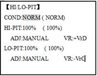
5.3.6 HIGH/LOW PITCH (HI/LO-PIT): This function may be used to adjust the curves high and low side individually for each flight condition (normal, idle-up 1, idle-up 2, idle-up 3, throttle hold).
ADJUSTABILITY: • You may define high and low side rate trim knobs (the high side pitch trim control is defined as the right side lever at initial setting). • The conditions are activated in the CONDITION SELECT function. • Both adjustments may be set to MANUAL, temporarily turning off the knob. • Adjustments may be memorized and then return the knobs to center point to use that amount of adjustment, allows easy use of the trimming knobs for multiple models.
OFFSET Optional separate trims in addition to those for the normal condition. This function is used to automatically change the trim of a helicopter, for example, when transitioned from hover to flying at high speed. A clockwise-rotation rotor helicopter tends to drift to the right at high speed, so an aileron offset may be applied to offset the helicopter to the left. The necessary elevator offset varies with model geometry, so it must be determined by noting collective pitch changes at high speed. The rudder offset is affected by both revo. mixing and trim lever movement while in the offset function.
• Complete switch assign ability, plus a CONDITION option that creates/ switches between individual trims for each of the idle-ups. • When OFFSET is active (its switch is on), moving the TRIM LEVERS adjust the stored offset, not the trims in the normal condition. •When OFFSET is inactive (its switch is off), the OFFSET and any trim adjustments to it have no effect (model obeys the trim settings of the currently-active flight condition.) • When OFFSET is inhibited, trim adjustments made in any flight condition affect all flight conditions. • Rapid jumps caused by large offsets can be slowed using the DELAY function. • During OFFSET operation, the aileron, elevator, and rudder travels are displayed on each trim display in the Startup screen.
Note: Remember, offsets and revo mixes are not recommended when using heading-hold/AVCS gyros because they conflict with the automatic corrections to trim and torque that AVCS provides.
5.3.8 DELAY: The Delay function provides a smooth transition between the trim positions whenever OFFSET, REVO, MIXING, or THROTTLE HOLD functions are turned on and off.
ADJUSTABILITY: • Separate delay times are available for aileron, elevator, rudder, throttle, and pitch. • With a 50% delay setting, the servo takes about a half-second to move to its new position, quite a long time. • In general, delays of approximately 10-15% are sufficient.
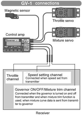
5.3.9 GOVERNORS: The Governor mixing function is used to adjust the Governor speed settings (rS1, rS2, rS3) from the transmitter. What is a governor? A governor is made up of a set of sensors which read the RPM of the helicopterЎЇs head, and a control unit that automatically adjusts the throttle setting to maintain a constant head speed regardless of changes in pitch of blades, weather conditions, etc. Governors are extremely popular in competition helicopters due to the consistency provided. How does it help in helicopter setup? The governor eliminates the need to spend large amounts of time setting up throttle curves, as it automatically adjusts the engineЎЇs RPM to maintain the desired head speed.
ADJUSTABILITY: • On/off may be separate from speed switching by plugging governor on/off into CH8 and changing CUT-CH setting. • If using separate on/off, switch assignment is totally adjustable. Be careful not assign governor off to a condition switch if you want the governor to function in that condition. • Speed switching and governor ON/OFF may be together using one switch or ON/OFF switching may be performed using an independent switch/channel. • When speed setting control uses CH7 and separate ON/OFF switch is not used, CH8 can be used for other functions. • In-flight adjustment of the head speed (for easy adjustment during turning) may be created using an additional channel and a programmable mix. The GV-1 controls throttle when it is active, so the throttle will not obey any FailSafe settings preset for throttle in the transmitter. Always set the FailSafe setting for the GV-1's on/off channel to OFF. This way the governor is shut off and the throttle obeys the FailSafe throttle commands.
5.3.10 Throttle Mixing (THROTTLE MIX):
This function can be set for each flight condition, and is used to correct the tendency of the model to change altitude when the rotor is tilted by aileron, elevator, and rudder controls. ADJUSTABILITY: • Mixing may be set from 0 to 100% each flight condition.
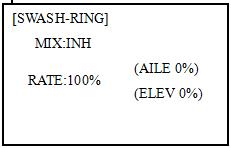
SWASH-RING
This function is to limit movement of swash plate to avoid damage to the SWASH ROB during operation aileron and ELEVATOR. It is affected in 3D flight. Movement of AILERON and ELEV is limited in the circle. ADJUSTABILITY: • Initial: 100% • adjusting range: 0-200%
|
||||||||||||||||||||||||||||||||||||||||||||||||||||||||||||||||||||||||||||||||||||||||||||||||||||||||||||||||||||||||||||||||||||||||||||||||||||||||||||||
|
|
Последнее изменение этой страницы: 2016-08-01; просмотров: 177; Нарушение авторского права страницы; Мы поможем в написании вашей работы! infopedia.su Все материалы представленные на сайте исключительно с целью ознакомления читателями и не преследуют коммерческих целей или нарушение авторских прав. Обратная связь - 18.221.217.100 (0.008 с.) |


 Note: The throttle and pitch curves for the normal condition is always on. They cannot be inhibited. The other four conditions are activated with their throttle curves or throttle hold.
 Note: There are three revo, mixes available: normal (NORM), idle-up 1/2 (IDL1/2), and idle-up 3 (IDL3). All 3 are adjustable in the ADVANCE menu. Never use revo mixing in conjunction with heading-hold/AVCS gyros. For details on revo, including default points for clockwise and counterclockwise rotating rotors.
 for 1s to BASIC.(If ADVANCE
  to THR-CURVE
  Ј
Ј  to point 1
  Ј
Ј  ЎЈ
ЎЈ
 Ј
Ј 
 to GYRO-SENSE
  to MIX


 to BASIC.
 again to ADVANCE menu.
  to 80%
 E (AT9) from NORMALto IDL2.Check the changes of rudder trim.


 E(AT9) from NORMALto IDL2.Check that the servos move gradually to new positions.

 or
or  as needed.
 again to ADVANCE