Заглавная страница Избранные статьи Случайная статья Познавательные статьи Новые добавления Обратная связь FAQ Написать работу КАТЕГОРИИ: ТОП 10 на сайте Приготовление дезинфицирующих растворов различной концентрацииТехника нижней прямой подачи мяча. Франко-прусская война (причины и последствия) Организация работы процедурного кабинета Смысловое и механическое запоминание, их место и роль в усвоении знаний Коммуникативные барьеры и пути их преодоления Обработка изделий медицинского назначения многократного применения Образцы текста публицистического стиля Четыре типа изменения баланса Задачи с ответами для Всероссийской олимпиады по праву 
Мы поможем в написании ваших работ! ЗНАЕТЕ ЛИ ВЫ?
Влияние общества на человека
Приготовление дезинфицирующих растворов различной концентрации Практические работы по географии для 6 класса Организация работы процедурного кабинета Изменения в неживой природе осенью Уборка процедурного кабинета Сольфеджио. Все правила по сольфеджио Балочные системы. Определение реакций опор и моментов защемления |
Crust, drillability, overburden, faulting and structural disorder, homogeneous and heterogeneous structures, streak.Содержание книги
Поиск на нашем сайте 1. The earth’s … consists of a variety of rocks formed under different circumstances and with a wide variety of properties. 2. More often, however, minerals will be mixed with others to form the various types of rocks and the properties will be combined to form both … 3. … is the colour of the mineral powder produced when a mineral is scratched or rubbed against unglazed, white porcelain and may be different from the colour of the mineral mass. 4. The … of a rock depends on the hardness of its constituent minerals and on the grain size and crystal form, if any. 5. Sedimentary rocks are formed by the deposition of material, by mechanical or chemical action, and its consolidation under the pressure of … 6. Due to nature of their formation, metamorphic zones will probably be associated with increased … and making the planning of mine development, and efficient drilling, more difficult.
4) Quote the sentences in which these words and word combinations are used: According to the Moh 10-point scale, to form part of, to combine readily, the behaviour of the rock structure, to exhibit hard-to-predict discontinuities, to be tilted and folded, due to ground movement, to cause a transformation in the internal structure, to necessitate prior grouting longhole drilling and blasting.
5) Give answers to the following questions: 1) What does the earth’s crust consist of? 2) What element makes up 50% of the earth’s crust by weight? 3) What minerals make up about 90% of the composition of the Earth’s crust? 4) What characteristics are important for correct mineral identification in the field before chemical analysis? 5) What does the drillability of a rock depend on?
6) Tell what you know about: 1) minerals comprising the Earth’s crust and their subdivisions 2) properties of rocks 3) types of rock and their classification for drilling subdivisions 4) rock classification for drilling Shaft Sinking for Access
Shafts are either sunk downwards or raised upwards. In mining, they form a system of vertically or inclined passageways, which are used for transportation of ore, refill, personnel, equipment, air, electricity, and ventilation. In underground construction and tunnels, shafts are driven for penstocks, cable ducts, ventilation, elevators, and surge chambers. In addition, they are driven as glory holes for transportation of material, which may not be accessible by any other means. For shaft raising. Atlas Copco has a choice of handheld pneumatic machine mounted on stoping airlegs. For sinking vertical shafts, the company produces rigs with up to nine machines, capable of parallel hole drilling.
Sinking Shafts Sink shafts are passageways sunk from the surface downwards, or underground from one level to another. The majority of the sink shafts are driven vertically. Shaft sinking is one of the most difficult and risky blasting jobs, as the work area is normally wet, narrow and noisy. Furthermore, the drilling and blasting crews are exposed to falling objects. The advance is slow, as the rock has to be removed between each blast with specialized equipment with limited capacity. The blasted rock must be fragmented, to suit the excavation equipment. The design of the cross section of the shaft principally depends on the quality of the rock. Nowadays, most shafts have a circular cross section, which gives better distribution of the rock pressure and decreases the need for reinforcement, especially at depth. The most common drilling and blasting methods are benching and blasting with pyramid cut. The benching method is a fast and efficient method, as the time-consuming cleaning of the floor between the blasts can be minimized. It is also easy to keep the shaft free from water, as a pump can always be placed in the lower blasted part of the shaft. The drilling and charging pattern is similar to that of smaller surface blasts. The burden and spacing vary with the hole diameter, but the drilling pattern is more closely spaced than for surface blasting, due to higher constriction. Shaft sinking with pyramid cuts is similar to tunnel blasting with V -cuts. The drilling is done with a drill-ring, which comprises a circular I-beam to which the drilling machines are fixed. The drill-ring may be fixed to the shaft walls with bolts, and the cut will be conical.
The explosives used in shaft sinking must always be water-resistant. Even if the ground is dry, the flushing water from the drilling will collect in the blastholes. For this reason, explosives with excellent water resistance properties are preferred. Emulsion explosives and dynamites are easily tamped to utilize the full hole volume, thus decreasing the number of holes, and the drilling and charging time. The specific charge in shaft sinking is rather high, ranging from 2.0 kg/cu m to 4.0 kg/cu m. The initiation of the blast may be done with electric or non-electric detonators. As a sink shaft is a small confined area, thunderstorms are a particular hazard, as stray currents tend to be transmitted down the shaft on pipes and cables. To avoid problems with evacuation of the blasting crew during a thunderstorm, NONEL detonators should be used.
Parallel Hole Drilling For high productivity shaft sinking, Atlas Copco has developed a drillrig for parallel hole drilling. The number of booms may vary between three and nine, in shafts with diameters from 6 m to 12 m. The drillrig is equipped with air-powered COP A15 drills, designed for hole sizes of 51 mm to 102 mm. The drilling pattern is a parallel hole cut with three large holes of 102 mm-diameter in a triangular shape. Blasthole diameter is 51 mm, and drill depth 3.6 m with an expected advance of 3.2 m. The drilling pattern is denser than in normal tunnel blasting, as smaller fragmentation is required to encourage the upward movement of the rock. Pumpable site-sensitized emulsions are preferable, due to their good water resistance and good fume characteristics. For the contour, a well-balanced cartridged explosive with a diameter of 17 mm to 20 mm should be used, to minimize overbreak. The specific drilling is high, at around 2.4 m/cu m, as is explosives consumption at 3 kg/cu m, values which vary with rock characteristics and shaft diameter. A non-electric initiation system, such as NONEL LP, is preferred in this type of operation, its 24 period numbers being sufficient for most shaft sinking rounds.
RBM Shafts
Full face boring of shafts by means of a raise boring machine (RBM), has for long been non-viable due to the lengths and diameters usually involved in shaft construction. Above that, another limiting parameter has always been the deviation of a RBM driven shaft of more than 1% by the hole length for long holes. Recent development however, has resulted in vertical drilling tools that enable close to vertical holes over more than 1,000 m-long, usually around 0.025% deviation by hole length. Such tools are normally equipped with a gyro striving towards the vertical line, as well as steering pads pressing against the rock wall to ensure a vertical direction. Such vertical-drilling tools are not yet fully developed for inclined applications. On the RBM side, there are very large diameter units available, featuring more than 10,000 kN of thrust and up to 1,000 kNm of torque, which are fully able to bore in excess of 6 m-diameter raises more than 1,000 m-long.
Lift Cage Raising
Raise shafting using a lift cage hanging on a wire rope through a large drillhole has been used since the 1940s, but it was not until the 1950s, when Boliden AB developed the JORA lift, that the method came into wider use. A large hole, diameter 110 mm to 150 mm, is drilled from an upper level in the centre of the intended shaft. A wire rope is lowered through the hole to the lower level, and a working plat-form with a lift cage is fastened to it. Using a winch, the platform is raised to the shaft face by remote control from the lift cage. The drilling and charging are carried out from the plat-form, on the top of the lift cage, and some scaling can be done from the cage, with the platform as protection. During the scaling, drilling and charging operations, the platform is fixed with bolts to the shaft walls. Before blasting, the platform is lowered down to a sledge, and towed aside. The wire rope is removed before blasting. The large hole is used as the cut for blasting the round, and advances of up to 4 m are obtained. The area is approximately 4 sq m, and the maximum height is 100 m. In this method, it is necessary to have free space above the shaft to drill the large hole and position the lifting gear.
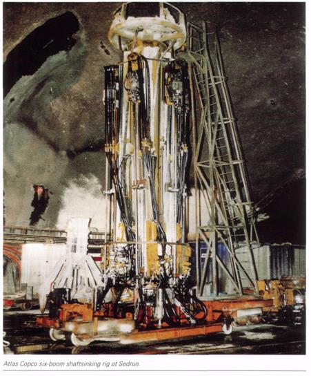
A good example of a recent vertically-sunk shaft is that at Sedrun, on the Gotthard AlpTransit railway tunnel. This was sunk to 800 m-deep from a chamber formed some 1.2 km inside the mountain, using an Atlas Copco shaftsinking rig equipped with six booms and COP A15 pneumatic rock drills. The rig was also used for cover drilling for injection holes around the shaft perimeter to keep water at bay. An Advance rate of 3-3.5 m/day was achieved, amounting to some 100 m/month working a 7 day/week. After four months of commissioning and running-in time of the system, this high performance was maintained throughout the project period of 18 months. The consortium comprised four Swiss contractors Murer, Zschokke Locher, Marti Tunnelbau, and CSC, together with South African company Shaft Sinkers International. The completed Sedrun shaft will be used for ventilation, maintenance, and emergency egress from an adjacent railway station. The 10 t-capacity, 700 m/min rock hoist used for shaftsinking will be rebuilt to suit tunnelling requirements. In order to maintain the high rate of progress, forming of the concrete lining was done in parallel with the general shaft sinking operation. Several other operations were also carried out in the shaft simultaneously. A platform provided five working decks. The lower Deck 5 was for managing activities at the bottom of the shaft; the concrete forms were mounted from Deck 3 for final lining in 6 m stages; concrete was received through long pipes on Deck 2 to be remixed and formed; and all supply lines were assembled on Deck 1
Shaft sinking is a speciality in South Africa because of the many deep mines in the country. So it follows that Atlas Copco South Africa has produced a series of drill rigs that are buiIt for this purpose. The rigs are designed for round shafts of diameters 6 m to 12m, with three to nine booms. The air-powered COP A15 rock drill relies on water flushing of the drill hole. Impact energy is 14 kW with an air pressure of 6 bar, requiring 300 lit/sec of air. It is designed for hole sizes of 51 mm-102 mm. At Sedrun, 51 mm was the choice, with penetration at 1.5 m/min. The contractor considers that the schistose gneiss at Sedrun was difficult to blast, as it required 2.9 kg to 3.6 kg of nitroglycerine-based explosive per cu m in an area of 58 sq m. The number of holes varied between 140 and 170, and they were normally drilled to a depth of 3.5 m to give the required advance of 3.2 m. The holes were vertical and in a circle. The opening was achieved by a parallel cut of three 102 mm holes placed in a triangle, and these larger holes were drilled with a DTH hammer placed in the centre of the rig. Each drilling period lasted about three hours. To control the inflow of water, continual pre-injection was carried out with 40 in-long holes drilled in a trumpet shape downwards, a method of cover drilling. Before blasting took place, the entire shaft-sinking stage had to be lifted 60 m above the bottom, to avoid possible damage by flying rock. Primary reinforcement was carried out during a pause in the loading cycle, installing 3 m-long Standard Swellex bolts and shotcrete. All the reinforcement work took up to 6h, and the total time invested in each round was, at best, some 19 h. The planned rhythm of one round per day was achieved after four months by the crew of some 140 operators. The contractors reported that the shaft-sinking rig worked well, and the project went according to plan, setting a new standard in the sinking of deep shafts.
List of words
Exercises: 1) Give Ukrainian equivalents of the following words and word combinations: To be exposed to falling objects, a circular cross-section, distribution of rock pressure, reinforcement, drilling and charging pattern, drilling and blasting methods, emulsion, explosives and dynamites, a boom, full face boring
2) Give English equivalents of the following words and word combinations: швидкість просування, вертикальне буріння, підйомний ствол,ствол шахти, відхилення, скат (схил), транспортування зруйнованоі породи самопливом,ініціювання вибуху, відкотний горизонт
3) Fill the blanks with the necessary words:
|
||
|
|
Последнее изменение этой страницы: 2016-06-29; просмотров: 377; Нарушение авторского права страницы; Мы поможем в написании вашей работы! infopedia.su Все материалы представленные на сайте исключительно с целью ознакомления читателями и не преследуют коммерческих целей или нарушение авторских прав. Обратная связь - 216.73.216.214 (0.009 с.) |

 Shafts for all Purposes
 Waterproof Explosives
 Sedrun Shaft
 Round Shafts