Заглавная страница Избранные статьи Случайная статья Познавательные статьи Новые добавления Обратная связь FAQ Написать работу КАТЕГОРИИ: ТОП 10 на сайте Приготовление дезинфицирующих растворов различной концентрацииТехника нижней прямой подачи мяча. Франко-прусская война (причины и последствия) Организация работы процедурного кабинета Смысловое и механическое запоминание, их место и роль в усвоении знаний Коммуникативные барьеры и пути их преодоления Обработка изделий медицинского назначения многократного применения Образцы текста публицистического стиля Четыре типа изменения баланса Задачи с ответами для Всероссийской олимпиады по праву 
Мы поможем в написании ваших работ! ЗНАЕТЕ ЛИ ВЫ?
Влияние общества на человека
Приготовление дезинфицирующих растворов различной концентрации Практические работы по географии для 6 класса Организация работы процедурного кабинета Изменения в неживой природе осенью Уборка процедурного кабинета Сольфеджио. Все правила по сольфеджио Балочные системы. Определение реакций опор и моментов защемления |
поршневой клапан Система управления подъемом
Service Manual
FOREWORD This manual contains an introductory description on SUZUKI XF650 and procedures for its in- spection/service and overhaul of its main components. Other information considered as generally known is not included. Read GENERAL INFORMATION section to familiarize yourself with outline of the vehicle and MAINTENANCE and other sections to use as a guide for proper inspection and service. This manual will help you know the vehicle better so that you can assure your customers of your optimum and quick service. GENERAL INFORMATION ENGINE * This manual has been prepared on the basis of the latest specification at the time of publication. If modification has been made since then, difference may exist between the content of this manual and the actual vehicle. * Illustrations in this manual are used to show the basic principles of operation and work procedures. They may not represent the actual vehicle exactly in detail. * This manual is intended for those who have enough knowledge and skills for servicing SUZUKI vehicles. Without such knowledge and skills, you should not attempt servicing by relying on this manual only. Instead, please contact your nearby authorized SUZUKI motorcycle dealer. ELECTRICAL SYSTEM SERVICING INFORMATION XF650W/UW/X/UX (’98, ’99-MODELS) XF650Y (2000-MODEL) © COPYRIGHT SUZUKI MOTOR CORPORATION 1996 SUZUKI MOTOR CORPORATION Overseas Service Department XF650K1 (’01-MODEL) CHASSIS FUEL AND LUBRICATION SYSTEM PERIODIC MAINTENANCE GROUP INDEX         
HOW TO USE THIS MANUAL
1. The text of this manual is divided into sections. 2. As the title of these sections are listed on the previous page as GROUP INDEX, select the section where what you are looking for belong. 3. Holding the manual as shown at the right will allow you to find the first page of the section easily. 4. On the first page of each section, its contents are listed. Find the item and page you need. COMPONENT PARTS AND WORK TO BE DONE Under the name of each system or unit, its exploded view is provided with work instruction and other service information such as the tightening torque, lubricating points and locking agent points.
© O-ring © Housing end (Inside) © Washer set © О-ring (2pcs) © Starter motor case © Armature © Washer set © Brush holder ® Brush spring ® Housing end (Outside) 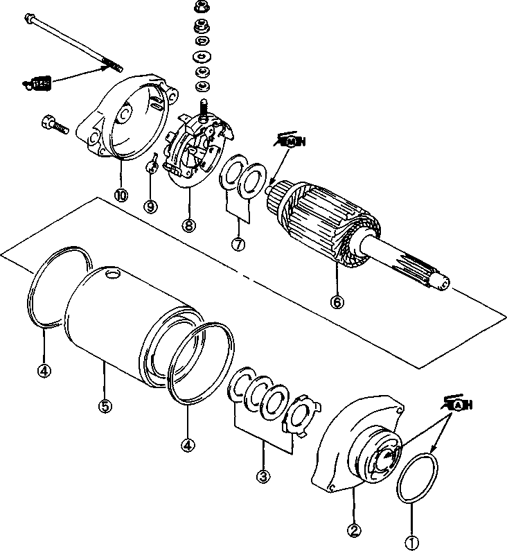 Example: Front wheel SYMBOL Listed in the table below are the symbols indicating instructions and other information necessary for servicing and meaning associated with them respectively. SYMBOL DEFINITION SYMBOL DEFINITION И Torque control required. Data beside it indicates specified torque. тШ Apply THREAD LOCK SUPER "1303". (99000-32030) "HP Apply oil. Use engine oil unless otherwise specified.
Use fork oil. (99000-99044-10G)
Apply SUZUKI SUPER GREASE "A". (99000-25010)
Apply or use brake fluid.
Apply SUZUKI SILICONE GREASE. (99000-25100) & Measure in voltage range.
Apply SUZUKI MOLY PASTE. (99000-25140)
Measure in resistance range.
Apply SUZUKI BOND "1215" (99000-31110) (Щ) Measure in current range.
Apply THREAD LOCK "1342" (99000-32050)
Use special tool.
Apply THREAD LOCK SUPER "1360". (99000-32130)
GENERAL INFORMATION
WARNING/CA UTION/NOTE...................................................................... 1- 1 GENERAL PRECAUTIONS......................................................................... 1- 1 SUZUKI XF650V ('97-MODEL).................................................................... 13 SERIAL NUMBER LOCATION.................................................................... 1-3 FUEL AND OIL RECOMMENDATION........................................................ 1-3 FUEL.......................................................................................................... 1- 3 ENGINE OIL.............................................................................................. 1- 3 BRAKE FLUID........................................................................................... 1-4 FRONT FORK OIL.................................................................................... 1- 4 BREAK-IN PROCEDURES......................................................................... 1- 4 INFORMATION LABELS.................................................................................. 1-5 SPECIFICATIONS........................................................................................ 1- 7 COUNTRY OR AREA.................................................................................. 1-9 WARNING/CAUTION/NOTE Please read this manual and follow its instructions carefully. To emphasize special information, the symbol and the words WARNING, CAUTION and NOTE have special meanings. Pay special attention to the messages highlighted by these signal words. AWARNING Indicates a potential hazard that could result in death or injury. A CAUTION Indicates a potential hazard that could result in vehicle damage. NOTE: Indicates special information to make maintenance easier or instructions dearer. Please note, however, that the warnings and cautions contained in this manual cannot possibly cover all potential hazards relating to the servicing, or lack of servicing, of the motorcycle. In addition to the WARNINGS and CAUTIONS stated, you must use good judgement and basic mechanical safety principles. If you are unsure about how to perform a particular service operation, ask a more experienced mechanic for advice. GENERAL PRECAUTIONS
• Proper service and repair procedures are important for the safety of the service mechanic and the safety and reliability of the vehicle. • When 2 or more persons work together, pay attention to the safety of each other. • When it is necessary to run the engine indoors, make sure that exhaust gas is forced outdoors. • When working with toxic or flammable materials, make sure that the area you work in is well-ventilated and that you follow all of the material manufacturer's instructions. • Never use gasoline as a cleaning solvent. • To avoid getting burned, do not touch the engine, engine oil or exhaust system during or for a while after engine operation. • After servicing fuel, oil, exhaust or brake systems, check all lines and fittings related to the system for leaks. AWARNING A CAUTION • If parts replacement is necessary, replace the parts with Suzuki Genuine Parts or their equivalent. • When removing parts that are to be reused, keep them arranged in an orderly manner so that they may be reinstalled in the proper order and orientation. • Be sure to use special tools when instructed. • Make sure that all parts used in reassembly are clean, and also lubricated when specified. • When use of a certain type of lubricant, bond, or sealant is specified, be sure to use the specified type. • When removing the battery, disconnect the negative cable first and then the positive cable. When reconnecting the battery, connect the positive cable first and then the negative cable, and replace the terminal cover on the positive terminal. • When performing service to electrical parts, if the service procedures not require use of battery power, disconnect the negative cable the battery. • Tighten cylinder head and case bolts and nuts, beginning with larger diameter and ending with smaller diameter, from inside to outside diagonally, to the specified tightening torque. • Whenever you remove oil seals, gaskets, packing, О-rings, locking washers, cotter pins, circlips, and certain other parts as specified, be sure to replace them with new ones. Also, before installing these new parts, be sure to remove any left over material from the mating surfaces. • Never reuse a circlip. When installing a new circlip, take care not to expand the end gap larger than required to slip the circlip over the shaft. After installing a circlip, always ensure that it is completely seated in its groove and securely fitted. • Do not use self-locking nuts a few times over. • Use a torque wrench to tighten fasteners to the torque values when specified. Wipe off grease or oil if a thread is smeared with them. • After reassembly, check parts for tightness and operation. • To protect environment, do not unlawfully dispose of used motor oil and other fluids: batteries, and tires. • To protect Earth's natural resources, properly dispose of used vehicles and parts.
RIGHT SIDE LEFT SIDE •Difference between photographs and actual motorcycles depends on the markets.  SUZUKI XF650V ('97-MODEL) SERIAL NUMBER LOCATION
FUEL AND OIL RECOMMENDATION FUEL Gasoline used should be graded 85-95 octane (Research Method) or higher. An unleaded gasoline type is recommended.
Make sure that the engine oil you use comes under API classification of SF or SG and that its viscosity rating is SAE 10W/40. If an SAE 10W/40 motor oil is not available, select an alternate according to the right chart. BRAKE FLUID Specification and classification: DOT 4 AWARNING
Since the brake system of this motorcycle is filled with a glycol-based brake fluid by the manufacturer, do not use or mix different types of fluid such as silicone-based and petroleum-based fluid for refilling the system, otherwise serious damage will result. Do not use any brake fluid taken from old or used or unsealed containers. Never re-use brake fluid left over from a previous servicing, which has been stored for a long period. FRONT FORK OIL Use fork oil #15. BREAK-IN PROCEDURES During manufacture only the best possible materials are used and all machined parts are finished to a very high standard but it is still necessary to allow the moving parts to "BREAK-IN" before subjecting the engine to maximum stresses. The future performance and reliability of the engine depends on the care and restraint exercised during its early life. The general rules are as follows. • Keep to these break-in engine speed limits: Initial 800 km ( 500 miles): Below 4 000 r/min Up to 1 600 km (1 000 miles): Below 6 000 r/min Over 1 600 km (1 000 miles): Below 8 000 r/min • Upon reaching an odometer reading of 1 600 km (1 000 miles) you can subject the motorcycle to full throttle operation. However, do not exceed 8 000 r/min. • Do not maintain constant engine speed for an extended time period during any portion of the break-in. Try to vary the throttle position. ТОРМОЗНАЯ ЖИДКОСТЬ Спецификация и классификация: DOT 4 Предупреждаю масло передней вилки Используйте вилочное масло №15. процедуры взлома При изготовлении используются только наилучшие материалы и все обрабатываемые детали завершены по очень высоким стандартам, но перед тем, как подвергнуть двигатель максимальным нагрузкам, необходимо разрешить подвижным частям "взлом". Будущая производительность и надежность двигателя зависят от осторожности и сдержанности, проявленных в течение его раннего срока службы. Общие правила таковы. • Держать в этих взлом ограничения скорости двигателя: Начальная 800 км ( 500 миль): ниже 4 000 об/мин До 1 600 км (1 000 миль): ниже 6 000 об/мин Более 1 600 км (1 000 миль): ниже 8 000 об/мин • По достижении показания одометра 1 600 км (1 000 миль) вы можете подвергнуть мотоцикл полный режим работы дроссельной заслонки. Однако, не более 8 000 об/мин. * Не поддерживайте постоянную частоту вращения двигателя в течение длительного периода времени во время обрыва. Постарайтесь изменить положение дроссельной заслонки.
INFORMATION LABELS  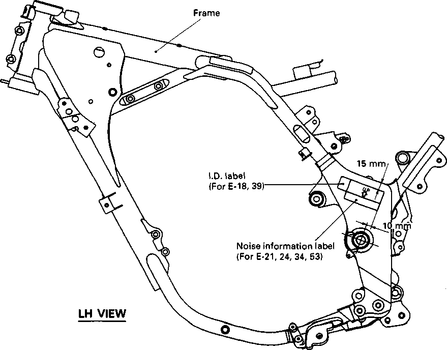
Fuel caution label (For E-02) Engine starting label Engine idle speed label Tire air pressure label
Swingarm Starter motor Warning safety label 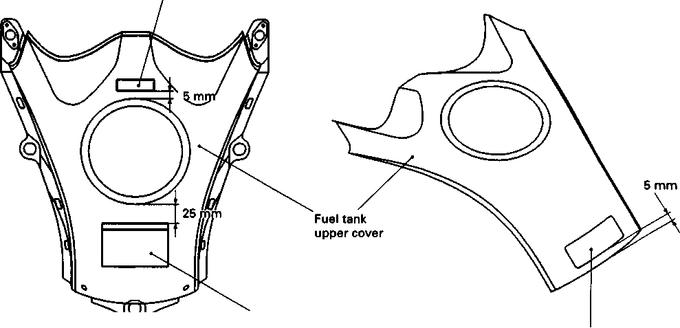 
SPECIFICATIONS DIMENSIONS AND DRY MASS Overall length .................................................... 2 205 mm (86.8 in) 2 190 mm (86.2 in) ...... Low seat conversion Overall width ..................................................... 865 mm (34.1 in) Overall height .................................................... 1 230 mm (48.4 in) 1 200 mm (47.2 in) ...... Low seat conversion Wheelbase.......................................................... 1 465 mm (57.7 in) 1 455 mm (57.2 in) ...... Low seat conversion Ground clearance.............................................. 200 mm ( 7.9 in) 170 mm ( 6.7 in) ....... Low seat conversion Seat height......................................................... 830 mm (32.7 in) 800 mm (31.5 in) ...... Low seat conversion Dry mass............................................................ 162 kg (357 lbs) ENGINE Type................................................................... Four-stroke, air-cooled, with SACS, OHC Valve clearance (IN) ......................................... 0.08-0.13 mm (0.003-0.005 in) (EX)....................................... 0.17-0.22 mm (0.007-0.009 in) Number of cylinders .......................................... 1 Bore.................................................................... 100 mm (3.937 in) Stroke................................................................. 82 mm (3.228 in) Piston displacement........................................... 644 cm3 (39.3 cu. in) Compression ratio ............................................. 9.5 : 1 Carburetor.......................................................... BSR32, twin Air cleaner.......................................................... Polyurethane foam element Starter system.................................................... Electric Lubrication system............................................. Wet sump TRANSMISSION Clutch ................................................................ Wet multi-plate type Transmission ..................................................... 5-speed constant mesh Gearshift pattern................................................ 1-down, 4-up Primary reduction ratio....................................... 2.178 (61/28) Gearratios, Low.................................................. 2.416 (29/12) 2nd .............................................. 1.625 (26/16) 3rd................................................ 1.238(26/21) 4th................................................ 1.000 (21/21) Top .............................................. 0.826 (19/23) Final reduction ratio............................................ 2.866 (43/15) Drive chain ..................................................... DID525 V9, 110 links CHASSIS Front suspension ............................................... Telescopic, coil spring, oil damped Rear suspension ................................................ Link type, coil spring, gas/oil damped, spring preload fully adjustable, compression damping force adjustable Front fork stroke................................................. 170 mm (6.7 in) 140 mm (5.5 in) ..... Low seat conversion Rear wheel travel .............................................. 167 mm (6.6 in) 132 mm (5.2 in) ..... Low seat conversion Steering angle.................................................... 43° Caster................................................................. 28° Trail..................................................................... 105 mm (4.13 in) Turning radius .................................................... 2.4 m (7.9 ft) Front brake ........................................................ Disk brake Rear brake......................................................... Disk brake Front tire size...................................................... 100/90-19 57H, tube type Rear tire size ..................................................... 130/80 R17 65H, tube type ELECTRICAL
Electronic ignition (CDI) 10° B.T.D.C. at 1500 rpm NGK CR10E or NIPPONDENSO U31ESR-N 12V 28.8 kC (8 Ah)/10 HR Three-phase A.C. generator 30/15/15/10/15/10A 12V 60/55W 12V 5W..... except E24 12V 21W 12V 5/21W 12V 1.7W x 2 12V 1.7W x 2 12V 1.7W 12V 1.7W Ignition type......................Ignition timing.................... Spark plug........................ Battery ............................. Generator ........................ Fuse.................................. Headlight........................... Parking or city light........... Turn signal light ................ Tail/brake light.................. Speedometer light ........... Turn signal indicator light Neutral indicator light ... High beam indicator light CAPACITIES Fuel tank, including reserve............................... 18.5 L (4.9/4.1 US/Imp gal) reserve .......................................... 4.5 L (1.2/1.0 US/Imp gal) Engine oil, oil change........................................ 2 300 ml (2.4/2.0 US/Imp qt) with filter change.............................. 2 400 ml (2.5/2.1 US/Imp qt) overhaul ........................................... 2 600 ml (2.7/2.3 US/Imp qt) Front fork oil (each leg) ..................................... 655 ml (22.1/23.1 US/Imp oz)
Low seat conversion 699 ml (23.6/24.6 US/Imp oz)ТЕХНИЧЕСКИЕ ТРЕБОВАНИЯ размеры и сухая масса Общая длина 2 205 мм (86.8 в) 2 190 мм (86.2 в) низкий преобразования сиденье Общая Ширина 865 мм (34.1 в) Общая высота 1 230 мм (48.4 в) 1 200 мм (47.2 в) низкий преобразования сиденье Колесная база: 1 465 мм (57.7 в) 1 455 мм (57.2 в) низкий преобразования сиденье Дорожный просвет 200 мм ( 7.9 в) 170 мм ( 6.7 в) низкий преобразования сиденье Высота сиденья 830 мм (32.7 в) 800 мм (31,5 дюйма) низкого преобразования сиденье Сухая масса 162 кг (357 фунтов) ДВИГАТЕЛЬ Тип четырехтактный, с воздушным охлаждением, с СЗК, ОНС Зазор клапана (дюйм) 0.08-0.13 mm (0.003-0.005 in) (EX) 0,17-0,22 мм (0,007-0,009 дюйма) Количество цилиндров 1 Диаметр отверстия 100 мм (3.937 in) Ход 82 мм (3.228 in) Смещение поршня 644 см3 (39.3 CU. в) Степень сжатия 9.5 : 1 Карбюратор BSR32, две Воздухоочиститель пенополиуретановый элемент Система стартера электрическая Система смазки мокрый Картер ПЕРЕДАЧА Сцепление мокрое многодисковое Тип Коробка передач 5-ступенчатая постоянного зацепления Схема переключения 1-вниз, 4-вверх Коэффициент первичного сокращения 2.178 (61/28) Gearratios, Низкий 2.416 (29/12) 2-й 1.625 (26/16) 3-й 1.238(26/21) 4-я 1.000 (21/21) Топ 0,826 (19/23) Окончательное передаточное число 2.866 (43/15) Цепь привода DID525 V9, 110 звеньев ШАССИ Передняя подвеска телескопическая, пружина, масло затухающих Задний тип соединения подвески, пружина катушки, демпфированный газ/масло, предварительной нагрузки пружины полностью регулируемая, демпфирующая сила сжатия регулируется Передний ход вилки 170 мм (6,7 дюйма) 140 мм (5,5 дюйма) Низкое сиденье преобразования Задние колеса 167 мм (6.6 в) 132 мм (5.2 в) низкий преобразования сиденье Угол поворота 43° Раковина 28° Тропа 105 мм (4.13 in) Радиус поворота 2,4 м (7,9 фута) Передний тормозной дисковый тормоз Задний тормозной дисковый тормоз Размер передней шины 100/90-19 57H, Тип трубки Размер задней шины 130/80 R17 65H, тип пробки ЭЛЕКТРИЧЕСКИЙ Тип зажигания Зажигание Свеча зажигания Батарея Генератор Взрыватель Фонарь Парковка или городской свет Световой сигнал поворота Хвост/стоп-сигнал Свет спидометра Контрольная лампа сигнала поворота Нейтральная контрольная лампа ... Высокий показатель световой луч МОЩНОСТИ Топливный бак, включая запас 18,5 л (4.9 / 4.1 US/Imp gal) резерв 4.5 L (1.2 / 1.0 US/Imp gal) Масло моторное, замена масла 2 300 мл (2.4 / 2.0 US/Imp Qt) с сменой фильтра 2 400 мл (2.5 / 2.1 US/Imp Qt) капитальный ремонт 2 600 мл (2.7 / 2.3 US/Imp Qt) Передняя вилка масло (каждой ногой) 655 мл (22.1/23.1 нас/имп ОЗ) 699 мл (23.6 / 24.6 US/Imp oz) 1-9 шеш щадящи м COUNTRY OR AREA The series of symbols on the left stand for the countries or area on the right. SYMBOL COUNTRY or AREA E-02 U.K. E-04 France E-15 Finland E-16 Norway E-17 Sweden E-18 Switzerland E-21 Belgium E-22 Germany E-24 Australia E-25 Netherlands E-26 Denmark E-34 Italy E-37 Brazil E-39 Austria E-53 Spain
E-15, 16 and 26 countries are included in E-17. E-21 and 53 countries are included in E-34. E-39 country is included in E-18. страна или район Серия символов слева обозначает страны или район справа. символ страны или области E-02 Великобритания. E-04 Франция E-15 Финляндия E-16 Норвегия E-17 Швеция E-18 Швейцария E-21 Бельгия E-22 Германия E-24 Австралия E-25 Нидерланды E-26 Дания E-34 Италия E-37 Бразилия E-39 Австрия E-53 Испания
Е-15, 16 и 26 стран входят в е-17. Е-21 и 53 страны включены в Е-34. Страна Е-39 включена в Е-18. PERIODIC MAINTENANCE ------------------------------------------- CONTENTS--------------------------------------------- PERIODIC MAINTENANCE SCHEDULE................................................... 2- 1 PERIODIC MAINTENANCE CHART...................................................... 2- 1 LUBRICATION POINTS........................................................................... 2-2 MAINTENANCE AND TUNE-UP PROCEDURES..................................... 2- 3 VALVE CLEARANCE................................................................................... 2-3 SPARKPLUGS......................................................................................... 2- 4 AIR CLEANER ELEMENT....................................................................... 2- 5 IDLE SPEED............................................................................................. 2- 6 THROTTLE CABLE PLAY....................................................................... 2- 7 CARBURETOR SYNCHRONIZATION ....................................................... 2-7 FUEL LINE................................................................................................ 2- 8 CLUTCH.................................................................................................... 2-8 ENGINE OIL AND OIL FILTER............................................................... 2- 9 DRIVE CHAIN.............................................................................................. 2-10 BRAKES.................................................................................................... 2-12 TIRES ........................................................................................................ 2-14 STEERING................................................................................................ 2-14 FRONT FORKS........................................................................................ 2-15 REAR SUSPENSION............................................................................... 2-15 EXHA UST PIPE AND MUFFLER BOLTS............................................. 2-15 CHASSIS BOLTS AND NUTS................................................................. 2-16 COMPRESSION PRESSURE CHECK....................................................... 2-18 OIL PRESSURE CHECK............................................................................. 2-19 ПЕРИОДИЧЕСКОЕ ОБСЛУЖИВАНИЕ ........................................................................................................................ ОГЛАВЛЕНИЕ ПЕРИОДИЧЕСКИЙ ГРАФИК ОБСЛУЖИВАНИЯ 2 - 1 ПЕРИОДИЧЕСКИЙ ГРАФИК ОБСЛУЖИВАНИЯ 2 - 1 Точки смазки 2-2 РЕМОНТ И НАСТРОЙКА ПРОЦЕДУР 2 - 3 зазор клапана 2-3 Свечи 2 - 4 ФИЛЬТРУЮЩИЙ ЭЛЕМЕНТ ВОЗДУХА 2 - 5 ЧАСТОТА ВРАЩЕНИЯ НА ХОЛОСТОМ ХОДУ 2 - 6 ТРОС ИГРАТЬ 2 - 7 Карбюратор синхронизации 2-7 ТОПЛИВОПРОВОД 2 - 8 муфта 2-8 МОТОРНОЕ МАСЛО И МАСЛЯНЫЙ ФИЛЬТР 2 - 9 Цепь привода 2-10 тормозов 2-12 шины 2-14 Управление рулем 2-14 передние вилки 2-15 Задняя подвеска 2-15 Болты трубы и глушителя EXHA Ust 2-15 Болты и гайки шасси 2-16 проверка давления сжатия 2-18 Проверка давления масла 2-19 PERIODIC MAINTENANCE SCHEDULE The chart below lists the recommended intervals for all the required periodic service work necessary to keep the motorcycle operating at peak performance and economy. Mileages are expressed in terms of kilometer, miles and time for your convenience. NOTE: More frequent servicing may be performed on motorcycles that are used under severe conditions. PERIODIC MAINTENANCE CHART INTERVAL: THIS INTERVAL SHOULD BE JUDGED BY ODOMETER READING OR MONTHS WHICHEVER COMES FIRST km 1 000 6 000 12 000 18 000 24 000 miles 4 000 7 500 11 000 15 000 months Valve clearance I - I - Spark plugs - I R I R Air cleaner element Clean every 3 000 km (2 000 miles). Idle speed I I I I Throttle cable play I I I I Carburetor synchronization - - I - Fuel line I I I I Replace every 4 years. Clutch I I I I Engine oil R R R R R Engine oil filter R - R - R Drive chain I I I I Clean and lubricate every 1 000 km (600 miles). Brakes I I I I Brake hose - I I I Replace every 4 years. Brake fluid - I I I Chang e every 2 years. Tires - I I I Steering I - I - Front forks - - I - Rear suspension - - I - Exhaust pipe and muffler bolts T - T - T Chassis bolts and nuts T T T T T NOTE: I: Inspection and adjust, clean, lubricate or replace as necessary. R: Replace T: Tighten
LUBRICATION POINTS Proper lubrication is important for smooth operation and long life of each working part of the motorcycle. Major lubrication points are indicated below.
NOTE: * Lubricate exposed parts which are subject to rust, with a rust preventative spray whenever the motorcycle has been operated under wet or rainy conditions. If the spray is unavailable, use either motor oil or grease. * Before lubricating each part, clean off any rusty spots and wipe off any grease, oil, dirt or grime. MAINTENANCE AND TUNE-UP PROCEDURES This section describes the servicing procedures for each item of the Periodic Maintenance requirements. VALVE CLEARANCE Inspect Initially at 1 000 km (600 miles, 2 months) and Every 12 000 km (7 500 miles, 24 months) thereafter. The valve clearance specification is different for intake and exhaust valves. Valve clearance adjustment must be checked and adjusted, 1) at the time of periodic inspection, 2) when the valve mechanism is serviced, and 3) when the camshaft is disturbed by removing it for servicing. Valve clearance (when cold): IN.: 0.08-0.13 mm (0.003-0.005 in) EX.: 0.17-0.22 mm (0.007-0.009 in) NOTE: Valve clearance is to be checked when the engine is cold.
the compression stroke. • Remove the seat and fuel tank. (Refer to page 4-3.) • Remove the engine protector. • Remove the one of each spark plug and both valve inspection caps. • Remove the valve timing inspection plug and magneto cover plug. • Turn the crankshaft counterclockwise with the box wrench to set the piston at T.D.C. on the compression stroke. (Turn the crankshaft until the "T" line (D on the magneto rotor is aligned with the center of hole on the magneto cover.) • Insert the thickness gauge into the clearance between the valve stem end and the adjusting screw on the rocker arm. 09900-20803: Thickness gauge 09917-14910: Valve clearance adjusting driver • If the valve clearance is out of the specification, bring it into the specified range. • Securely tighten the lock nut after adjustment is completed. A CAUTION Both right and left valve clearances, should be as closely set as possible. • Reinstall the spark plug, valve inspection caps, valve timing inspection plug and magneto cover plug. SPARK PLUGS Inspect Every 6 000 km (4 000 miles, 12 months) and Replace Every 12 000 km (7 500 miles, 24 months).
• Remove the spark plugs. 1ИЧ1 09930-10121: Spark plug socket wrench set — - Standard Hot type NGK CR10E CR9E ND U31ESR-N U27ESR-N

CARBON DEPOSIT Check to see if there are carbon deposits on the spark plugs. If carbon is deposited, remove it with a spark plug cleaner machine or carefully using a tool with a pointed end. SPARK PLUG GAP Measure the spark plug gap with a thickness gauge. If out of specification, regap the spark plug.
Standard Spark plug gap 0.7-0.8 mm (0.028-0.031 in) 09900-20803: Thickness gauge
ELECTRODE'S CONDITION Check to see the worn or burnt condition of the electrodes. If it is extremely worn or burnt, replace the plug. And also replace the plug if it has a broken insulator, damaged thread, etc. A CAUTION
AIR CLEANER ELEMENT Clean Every 3 000 km (2 000 miles). If the air cleaner is clogged with dust, intake resistance will be increased with a resultant decrease in power output and an increase in fuel consumption. Check and clean the element in the following manner. • Remove the seat. • Remove the air cleaner case cover by removing screws ©• • Remove the air cleaner element by removing the wing nut @. • Remove the polyurethane foam element ® from the element frame @. • Fill a washing pan of a proper size with non-flammable cleaning solvent. Immerse the element in the cleaning solvent and wash it clean. • Squeeze the cleaning solvent out of the washed element by pressing it between the palms of both hands. • Immerse the element in motor oil, and squeeze the oil out of the element leaving it slightly wet with oil. NOTE: Do not twist or wring the element because it will tear or the individual cells of the element will be damaged. A CAUTION Inspect the element carefully for rips, torn seams, etc. If any damage is noted, replace the element. • Reinstall the cleaned or new cleaner element in the reverse order of removal. A CAUTION
Non-flammable (m| cleaning solvent \Д _ * •* ‘‘i . i s« - __ - 1QW/AO t”5? OIL If driving under dusty conditions, clean the air cleaner element more frequently. The surest way to accelerate engine wear is to use the engine without the element or to use a torn element. Make sure that the air cleaner is in good condition at all times. Life of the engine depends largely on this component! NOTE: When you clean the air cleaner element, drain water from the air cleaner drain hoses by removing the drain plugs.
Inspect Initially at 1 000 km (600 miles, 2 months) and Every 6 000 km (4 000 miles, 12 months) thereafter. IDLE SPEED NOTE: Make this adjustment when the engine is warm. • Connect a tachometer. 09900-26006: Tachometer • Start up the engine and set its speed at anywhere between 1 400 and 1 600 r/min (1 450 and 1 550 r/min for Switzerland and Austria) by turning the throttle stop screw ф. • Turn in the pilot screw fully. Turn out the screw 3 turns. • Turn and search the pilot screw position where highest engine speed is available to fine-tune the carburetor setting. NOTE: Turn in or out the pilot screw within 1/2 turn from the standard setting. • Recheck the idle speed and adjust to between 1 400 and 1 600 r/min (1 450 and 1 550 r/min for Switzerland and Austria) with throttle stop screw if necessary. Idle speed:
1 500 i 100 r/min ... for the Others THROTTLE CABLE PLAY Inspect Initially at 1 000 km (600 miles, 2 months) and Every 6 000 km (4 000 miles, 12 months) thereafter. A twin throttle cable system is used in this motorcycle. Cable ф is for pulling and cable ® is for returning. To adjust the cable play, adjust the returning cable first and then adjust the pulling cable. Returning cable play The returning cable should be adjusted to have a thread length @ of 2-3 mm (0.08-0.12 in) as shown in the Fig. If the adjustment is necessary, adjust the thread length in the following way: • Loosen the lock nut ®. • Turn the nut @ to obtain the thread length ® of 2-3 mm (0.08-0.12 in). • Tighten the lock nut (D securely. Pulling cable play The pulling cable should be adjusted to have a cable play d) of 0.5-1.0 mm (0.02-0.04 in) as shown in the Fig. If the adjustment is necessary, adjust the cable play in the following way: • Turn the handlebar all the way to the left. • Loosen the lock nuts (©, ©). • Turn the adjuster ф or (D to obtain the cable play ® of 0.5-1.0 mm (0.02-0.04 in). • Tighten the lock nuts (©, ©) securely.
After the adjustment is completed, check that handlebar movement does not raise the engine idle speed and that the throttle grip returns smoothly and automatically.
CARBURETOR SYNCHRONIZATION Inspect Every 12 000 km (7 500 miles, 24 months).
Inspect Initially at 1 000 km (600 miles, 2 months) and Every 6 000 km (4 000 miles, 12 months) thereafter. FUEL LINE Inspect Initially at 1 000 km (600 miles, 2 months) and Every 6 000 km (4 000 miles, 12 months) thereafter. Replace Every 4 years. CLUTCH • Loosen the lock nut ф and turn the clutch cable adjuster ® fully in. • Slide the cover ®. • Loosen the lock nut @ and turn the clutch cable adjuster © to provide the specified clutch lever play @. Clutch lever play 10-15 mm (0.4-0.6 in) • Tighten the lock nuts (ф and ®) while holding the adjusters (ф and (D) in positions. • Slide the cover ® to original position. NOTE: Minor adjustment can be made by the adjuster (2) after loosening the lock nut ф. At the same intervals, lubricate
(OIL FILTER) Replace Initially at 1 000 km (600 miles, 2 months) and Every 12 000 km (7 500 miles, 24 months) thereafter. ENGINE OIL AND OIL FILTER (ENGINE OIL) Replace (Change) Initially at 1 000 km (600 miles, 2 months) and Every 6 000 km (4 000 miles, 12 months) thereafter. Oil should be changed while the engine is warm. Oil filter replacement at the above intervals should be done together with engine oil change. • Keep the motorcycle upright, supported by jack or wooden block. • Place an oil pan below the engine and remove the engine oil drain plug ф and oil filler cap (D to drain engine oil. • Remove the oil filter cap by removing the three bolts ®. • Remove the oil filter @ and install the new one. • Install the oil filter cap and tighten the bolts d> securely. NOTE: Before installing the oil filter and oil filter cap, check to be sure that the spring (§> and new О-rings I'd) and ф) are installed correctly and apply engine oil lightly to the new O-ring ©. • Tighten the oil drain plug ф securely, and pour fresh oil through the oil filler. The engine will hold about 2 300 ml of oil. Use an API classification of SF or SG oil with SAE 10W/40 viscosity. [4 Drain plug: 24 N-m (2.4 kg-m, 17.5 Ib-ft) • Install the oil filler cap d). • Start up the engine and allow it to run for several minutes at idling speed. • Turn off the engine and wait about one minute, then check the oil level through the inspection window d). If the level is below mark "F", add oil to the level. NECESSARY AMOUNT OF ENGINE OIL Oil change : 2 300 ml (2.4/2.0 US/Imp qt) Filter change : 2 400 ml (2.5/2.1 US/Imp qt)
DRIVE CHAIN Inspect Initially at 1 000 km (600 miles, 2 months) and Every 6 000 km (4 000 miles, 12 months) thereafter. Clean and Lubricate Every 1 000 km (600 miles). Visually check the drive chain for the possible defects listed below. (Support the motorcycle by a jack and a wooden block, turn the rear wheel slowly by hand with the transmission shifted to Neutral.) * Loose pins [1] Excessive wear * Damaged rollers * Improper chain adjustment * Dry or rusted * Missing О-ring seals * Kinked or binding links If any defects are found, the drive chain must be replaced. NOTE: When replacing the drive chain, replace the drive chain and sprockets as a set. CHECKING • Loosen the axle nut (T). • Loosen both chain adjuster lock nuts ®. • Tense the drive chain fully by turning both chain adjuster bolts d). • Count out 21 pins (20 pitches) on the chain and measure the distance between the two points. If the distance exceeds the service limit, the chain must be replaced.
Service Limit Drive chain 20-pitch length 319.4 mm
(12.6 in)
ADJUSTING • Loosen or tighten both chain adjuster bolts d) until the chain has 20-30 mm (0.8-1.2 in) of slack in the middle between engine and rear sprockets. The marks @ on both chain adjusters must be at the same position on the scale to ensure that the front and rear wheels are correctly aligned. • Place the motorcycle on its side-stand for accurate adjustment. • After adjusting the drive chain, tighten the axle nut ф to the specified torque. • Tighten both chain adjuster lock nuts ® securely.
CLEANING AND LUBRICATING • Wash the chain with kerosene. If the chain tends to rust quickly, the intervals must be shortened. A CAUTION Do not use trichlene, gasoline or any similar fluids: These fluids have too great a dissolving power for this chain and, what is more important, they can damage the "0"-rings (or seals) confining the grease in the bush to pin clearance. Remember, high durability comes from the presence of grease in that clearance. • After washing and drying the chain, oil it with a heavyweight motor oil.
The brake system of this motorcycle is filled with a glycol-based brake fluid. Do not use or mix different types of fluid such as silicone-based or petroleum- based. Do not use any brake fluid taken from old, used or unsealed containers. Never re-use brake fluid left over from the last servicing or stored for a long period. BRAKES___________________________________ (BRAKE) Inspect Initially at 1 000 km (600 miles, 2 months) and Every 6 000 km (4 000 miles, 12 months) thereafter. (BRAKE HOSE AND BRAKE FLUID) Inspect Every 6 000 km (4 000 miles, 12 months). Replace hoses Every 4 years. Replace fluid Every 2 years. BRAKE FLUID LEVEL • Keep the motorcycle upright and place the handlebars straight. • Check the brake fluid level by observing the lower limit lines on the front and rear brake fluid reservoirs. • When the level is below the lower limit line, replenish with brake fluid that meets the following specification. ^ Specification and Classification: DOT 4 AWARNING AWARNING Brake fluid, if it leaks, will interfere with safe running and immediately discolor painted surfaces. Check the brake hoses and hose joints for cracks and oil leakage before riding. BRAKE PADS The extent of brake pad wear can be checked by observing the grooved limit line ф on the pad. When the wear exceeds the grooved limit line, replace the pads with new ones. (Refer to pages 5-39 and 5-46.) A CAUTION______________________________________ Replace the brake pad as a set, otherwise braking performance will be adversely affected. BRAKE PEDAL HEIGHT • Loosen the lock nut ф and rotate the push rod ф to locate brake pedal 5 mm below the top face of the footrest. • Retighten the lock nut 0 to secure the push rod ф in the proper position.
Air trapped in the fluid circuit acts like a cushion to absorb a large proportion of the pressure developed by the master cylinder and thus interferes with the full braking performance of the brake caliper. The presence of air is indicated by "sponginess" of the brake lever and also by lack of braking force. Considering the danger to which such trapped air exposes the machine and rider, it is essential that, after remounting the brake and restoring the brake system to the normal condition, the brake fluid circuit be purged of air in the following manner: • Fill up the master cylinder reservoir to the "UPPER" line. Replace the reservoir cap to prevent entry of dirt. • Attach a pipe to the caliper bleeder valve, and insert the free end of the pipe into a receptacle. Д] Air bleeder valve: 8 N-m (0.8 kg-m, 6.0 Ib-ft) • Front brake: Bleed the air from the air bleeder valve. • Squeeze and release the brake lever several times in rapid succession and squeeze the lever fully without releasing it. Loosen the bleeder valve by turning it a quarter of a turn so that the brake fluid runs into the receptacle; this will remove the tension of the brake lever causing it to touch the handlebar grip. Then, close the valve, pump and squeeze the lever, and open the valve. Repeat this process until the fluid flowing into the receptacle no longer contains air bubbles. NOTE: Replenish the brake fluid in the reservoir as necessary while bleeding the brake system. Make sure that there is always some fluid visible in the reservoir. • Close the bleeder valve, and disconnect the pipe. Fill the reservoir with brake fluid to the "UPPER" end of the inspection window. A CAUTION Handle brake fluid with care: the fluid reacts chemically with paint, plastics, rubber materials etc. [3] TIRES Inspect Every 6 000 km (4 000 miles, 12 months). TIRE TREAD CONDITION Operating the motorcycle with excessively worn tires will decrease riding stability and consequently invite a dangerous situation. It is highly recommended to replace a tire when the remaining depth of tire tread reaches the following specification. Tire tread depth limit: FRONT & REAR 3.0 mm (0.12 in) TIRE PRESSURE If the tire pressure is too high or too low, steering will be adversely affected and tire wear increased. Therefore, maintain the correct tire pressure for good roadability or shorter tire life will result. Cold inflation tire pressure is as follows. COLD INFLATION TIRE PRESSURE SOLO RIDING DUAL RIDING kPa kg/cm2 psi kPa kg/cm2 psi FRONT 1.75 1.75 REAR 2.00 2.25
A CAUTION The standard tire fitted on this motorcycle is 100/90-18 57H for front and 130/80 R17 65H for rear. The use of tires other than those specified may cause instability. It is highly recommended to use a SUZUKI Genuine Tire. TIRE TYPE PIRELLI (front ... MT80, rear ... MT80RS)
Inspect Initially at 1 000 km (600 miles, 2 months) and Every 12 000 km (7 500 miles, 24 months) thereafter. STEERING
FRONT FORKS Inspect Every 12 000 km (7 500 miles, 24 months). Inspect the front forks for oil leakage, scoring or scratches on the outer surface of the inner tubes. Replace any defective parts, if necessary. (Refer to page 5-11.) REAR SUSPENSION Inspect Every 12 000 km (7 500 miles, 24 months). Inspect the rear shock absorber for oil leakage and check that there is no play in the swingarm assembly. EXHAUST PIPE AND MUFFLER BOLTS
CHASSIS BOLTS AND NUTS Tighten Initially at 1 000 km (600 miles, 2 months) and Every 6 000 km (4 000 miles, 12 months) thereafter. Check that all chassis bolts and nuts are tightened to their specified torque. (Refer to page 2-17 for the locations of the following nuts and bolts on the motorcycle.) Item N-m kg-m Ib-ft © Steering stem head nut 9.0 65.0 © Front fork upper clamp bolt 2.9 21.0 ® Front fork lower clamp bolt 2.3 16.5 © Front fork cap bolt 2.3 16.5 © Front axle 6.5 47.0 © Front axle holder bolt 2.3 16.5 ® Handlebars clamp bolt 2.3 16.5 © Handlebars holder set nut 2.5 18.0 ® Front brake master cylinder mounting bolt 1.0 7.0 ® Front brake caliper mounting bolt 3.9 28.0 © Brake hose union bolt (Front & Rear) 2.3 16.5 @ Brake air bleeder valve (Front & Rear) 0.8 6.0 © Brake disc bolt (Front & Rear) 2.3 16.5 @ Rear brake caliper pad mounting bolt 1.8 13.0 © Rear brake caliper mounting bolt 2.3 16.5 © Rear brake master cylinder mounting bolt 1.0 7.0 @ Rear brake master cylinder rod lock nut 1.8 13.0 ® Front footrest bracket mounting bolt 5.5 40.0 © Rear footrest bracket mounting bolt 2.3 16.5 © Swingarm pivot nut 7.7 55.5 © Rear shock absorber mounting bolt (Upper & Lower) 4.5 32.5 @ Rear cushion lever/rod mounting nut 10.0 72.5 © Rear cushion lever mounting nut (Front) 8.0 58.0 ©Rear axle nut 11.0 79.5 © Rear sprocket nut/bolt 2.7 19.5
COMPRESSION PRESSURE CHECK The compression of a cylinder is a good indicator of its internal condition. The decision to overhaul the cylinder is often based on the results of a compression test. Periodic maintenance records kept at your dealership should include compression readings for each maintenance service. COMPRESSION PRESSURE SPECIFICATION Standard 850 kPa Approx. /8.5kg/cm2\ \ 120 psi ) Low compression pressure can indicate any of the following conditions: * Excessively worn cylinder wall * Worn-down piston or piston rings * Piston rings stuck in grooves * Poor seating of valves * Ruptured or otherwise defective cylinder head gasket COMPRESSION TEST PROCEDURE NOTE: * Before testing the engine for compression pressure, make sure that the cylinder head bolts are tightened to the specified torque values and valves are properly adjusted. * Have the engine warmed up by idling before testing. * Be sure that the battery used is in fully-charged condition.
pressure in the following manner. • Remove both spark plug caps. • Remove either one of two plugs. • Fit the compression gauge in the plug hole, while taking care that the connection tight. • Keep the throttle grip in full-open position. • While cranking the engine a few seconds with the starter, and record the maximum gauge reading as the compression of that cylinder. 09915-64510: Compression gauge 09915-63310: Adaptor OIL PRESSURE CHECK
Above 30 kPa (0.3 kg/cm2, 4.3 psi) Below 70 kPa (0.7 kg/cm2, 10 psi) at 3 000 г/min.. Oil temp, at 60°C (140°F) Check periodically the oil pressure in the engine to judge roughly the condition of the moving parts. OIL PRESSURE SPECIFICATION If the oil pressure is lower or higher than the specification, the following causes may be considered. LOW OIL PRESSURE * Oil leakage from the oil passage way * Damaged O-ring * Defective oil pump * Combination of above items HIGH OIL PRESSURE * Used a engine oil which is too high viscosity * Clogged oil passage way * Combination of above items OIL PRESSURE TEST PROCEDURE Check the oil pressure in the following manner. • • Install the oil pressure gauge in the position shown in the figure. • Warm up the engine as follows: Summer 10 min. at 2 000 r/min. Winter 20 min. at 2 000 r/min. • After warming up, increase the engine speed to 3 000 r/min. (with the engine tachometer), and read the oil pressure gauge. 09915-74510: Oil pressure gauge 09900-26006: Tachometer ENGINE --------------------------- CONTENTS--------------- ENGINE COMPONENTS REMOVABLE WITH THE ENGINE IN PLACE..................................................................... 3-1 ENGINE REMOVAL AND REINSTALLATION.......................... 3-2 ENGINE DISASSEMBLY AND REASSEMBLY........................ 3-9 Ю CYLINDER HEAD COVER/ROCKER ARM ЗА CAMSHAFT/CYLINDER HEAD/VALVES 3B CYLINDER/PISTON 3C STARTER MOTOR/GENERATOR ROTOR/GEARSHIFT 3D CLUTCH 3E GEARSHIFT CAM/TRANSMISSION 3F BALANCER SHAFT/CRANKSHAFT/CRANKCASE 3G ENGINE LUBRICATION SYSTEM 3H
ENGINE COMPONENTS REMOVABLE WITH THE ENGINE IN PLACE The parts listed below can be removed and reinstalled without removing the engine from the frame. Refer to the page listed in each section for removal and reinstallation instructions. ENGINE CENTER Refer to page Cam chain tensioner........................... 3-10. and 28 Cylinder head cover........................... 3A-1. and 4 Camshaft ........................................... 3B-1. and 11 Cylinder head...................................... 3B-1. and 11 Cylinder ............................................. 3C-1. and 3 Piston ................................................. 3C-1. and 3 Starter motor....................................... 3D-1. and 3 Cam chain........................................... 3-13. and 21
ENGINE LEFT SIDE ENGINE RIGHT SIDE
Refer to page Engine sprocket................................. 3-3 and 7 Generator cover ................................ 3D-1 and 3 Starter torque limiter.......................... 3D-1 Starter idle gear.................................. 3D-1 Generator rotor ................................. 3D-1 and 3 Starter gear........................................ 3D-1 Gearshift shaft................................... 3D-2 Gearshift pawls and cam driven gear......................................... 3D-2 Refer to page Clutch cover ..................................... 3-11. and 24 Clutch................................................. 3-11. and 23 Primary drive gear............................ 3-13. and 21 Oil pump............................................ 3-14. and 21 Neutral position indicator switch .... 3-14 and 20 Oil filter............................................. 3H-1
ENGINE REMOVAL Before taking the engine out of the frame, wash the engine with a steam cleaner. Engine removal is sequentially explained in the following steps. • Remove the oil drain plug 0 to drain the engine oil. • Remove the seat. (Refer to page 5-2.) • • Disconnect the battery © lead wire © from the battery terminal. • Remove the engine protector @. • Remove the frame covers. (Refer to page 5-4.) • Remove the fuel tank. (Refer to page 4-3.) [5] • Remove the muffler mounting bolts Q. • Remove the muffler (2) by loosening the connecting bolt • Remove the exhaust pipe. • Remove the oil cooler pipe mounting bolts. • Remove the left front footrest 0. Remove the engine sprocket cover © and gearshift pedal ©. • Remove the engine sprocket bolts while depressing the rear brake pedal. • Remove the plate ® and damper (f). • Remove the engine sprocket. NOTE: If it is difficult to remove the engine sprocket, loosen the rear axle nut and chain adjusters to provide additional chain slack. • Remove the right front footrest 0. • Remove the rear brake pedal. • Remove the clutch release arm from the clutch release pinion. Remove the clutch cable (2) from the clutch cable guide. • Disconnect the spark plug caps. • Remove the carburetors. (Refer to page 4-12.) • • Disconnect the pick-up coil/power source coil lead wire coupler 0 from the CDI unit. • Disconnect the rear brake lamp switch lead wire coupler (2). Remove the lead wires from the clamps. • Disconnect the generator coil and neutral position indicator switch lead wire couplers. Remove the lead wires from the clamps.
ENGINE REINSTALLATION Reinstall the engine in the reverse order of engine removal. • Insert the two long bolts from the left side. Install the brackets, spacers, bolts and nuts properly, as shown in the following illustration. NOTE: The engine mounting nuts are self-locking. Once the nuts have been removed, they are no longer of any use. Be sure to use new nuts and tighten them to the specified torque.
И 
ITEM N-m kg-m Ib-ft ® 4.0 29.0 ® © ® © 6.5 47.0 © © 4.0 29.0 (8) 2.3 16.5
LENGTH Bolt 0 53 mm (2.1 in) Bolt © 100 mm (3.9 in) Bolt© 235 mm (9.3 in) Bolt® 235 mm (9.3 in) Bolt© 130 mm (5.1 in) Spacer © 27 mm (1.1 in) Spacer © 65 mm (2.6 in)
• When installing the brake pedal, replace the cotter pin with a new one. • Tighten the right front footrest bolts to the specified torque. И Right front footrest bolt: 39 N*m (3.9 kg-m, 28.0 lb-ft) • Apply THREAD LOCK SUPER "1303" to the engine sprocket mounting bolts and tighten them to the specified torque. ТЙй) 99000-32030: THREAD LOCK SUPER "1303" H Engine sprocket bolt: 6 N«m (0.6 kg-m, 4.5 lb-ft) • Tighten the left front footrest bolts to the specified torque. W Left front footrest bolt: 39 N«m (3.9 kg-m, 28.0 lb-ft) • Properly install the oil cooler pipes onto the clutch cover and cylinder head. A CAUTION Replace the O-rings 0 with new ones to prevent oil leakage. • Tighten the oil pipe bolts to the specified torque.
• After remounting the engine, route the wire harnesses, cables and hoses properly by referring to the wire routing, cable routing and hose routing sections. (Refer to pages 7-10 through 7-22.) • Adjust the following items: * Throttle cable play........................... (Refer to........ page 2-7.) * Idle speed......................................... (Refer to........ page 2-6.) * Clutch lever play.............................. (Refer to........ page 2-8.) * Drive chain slack........................... (Refer to page 2-10.) • Pour 2.6 L (2.7/2.3 US/Imp qt) of engine oil SAE 10W/40 graded SF or SG into the engine after overhauling it. * Oil change (without oil filter replacement) 2 300 ml (2.4/2.0 US/Imp qt) Oil change (with oil filter replacement) 2 400 ml (2.5/2.1 US/Imp qt) Engine overhaul 2 600 ml (2.7/2.3 US/Imp qt)
ENGINE DISASSEMBLY • Remove the oil pipe by removing the mounting bolts. • Remove the two spark plugs. • Remove the generator cover by removing the bolts. • Remove the dowel pin and gasket. NOTE: Before removing the cylinder head cover, the piston must be at Top Dead Center (TDC) on the compression stroke. Align the "T" тагкф on the generator rotor with the index mark (2) on the crankcase. [7] • Loosen the cylinder head cover bolts in ascending order and then remove the cylinder head cover. • Remove the dowel pins. • Remove the cam chain tensioner adjuster by removing the bolts. • Flatten the camshaft sprocket lock washer and remove the camshaft sprocket bolts. • Remove the C-ring 0, camshaft sprocket and camshaft. NOTE: The cam chain tensioner bolt 0 is to be removed only when disassembling the engine. A CAUTION Do not drop the cam chain, pin, C-ring or camshaft sprocket into the crankcase. • Loosen the cylinder head bolts and nuts in a crisscross pattern, then remove them. • Remove the cylinder head. NOTE: If it is difficult to remove the cylinder head, gently pry it off while tapping the finless portion of the cylinder head with a plastic hammer. Be careful not to break the fins.
• • Remove the cylinder by removing the nuts. A CAUTION Be careful not to damage the fins when removing or handling the cylinder. • Remove the dowel pins and gasket. • Place a clean rag over the cylinder base to prevent the piston pin circlips from dropping into the crankcase. Remove the piston pin circlips with long-nose pliers. • Remove the piston by removing the piston pin. • Remove the clutch cover by removing the bolts. • Remove the clutch pressure plate by loosening the clutch spring bolts in a crisscross pattern. Remove the clutch release rack. [8]
НФЯ • Flatten the lock washer and remove the clutch sleeve hub nut with the special tool.09920-53740: Clutch sleeve hub holder • Remove the lock washer, concave washer and clutch sleeve hub. • Remove the thrust washer 0 and primary driven gear assembly. • Remove the thrust washer 0.
• Remove the starter torque limiter (3), starter idle gear 0 and starter idle gear shaft. • Loosen the generator rotor bolt with a 36 mm offset wrench. NOTE: Do not remove the generator rotor bolt after loosening it. The generator rotor bolt is used in conjunction with the rotor remover, when removing the generator rotor. • Remove the generator rotor with the special tool. 09930-30721: Rotor remover • Remove the key 0. • Remove the starter gear 0. • Loosen the ring nut with special tool by holding the primary drive gear nut. 09917-23711: Ring nut socket wrench NOTE: Do not remove the ring nut after loosening it. • Temporarily install the starter gear, key, generator rotor and generator rotor bolt onto the crankshaft. NOTE: Do not tighten the generator rotor bolt. • Remove the primary drive gear nut by holding the generator rotor. A CAUTION The primary drive gear nut has left-hand threads. • Remove the generator rotor, key and starter gear. • • 1ЕИ1    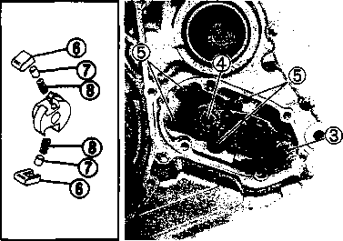  Remove the concave washer, primary drive gear and cam chain 0. Remove the concave washer, primary drive gear and cam chain 0.
• Remove the generator rotor bolt, generator rotor, key, starter gear, thrust washer and ring nut. • Remove the crankcase oil separator 0 by removing the screws. • Remove the gearshift cover by removing the bolts. Remove the gasket and dowel pins. • Remove the gearshift shaft ® and cam driven gear 0 by removing the screws ©. NOTE: When removing the cam driven gear, do not lose the gearshift pawls ©, pins ф and springs ®. [9]
• Remove the neutral position indicator switch. NOTE: Do not lose the neutral position indicator switch contactQ and spring (2). • Remove the crankcase securing bolts. • Separate the left and right crankcases. 09920-13120: Crankcase separating tool 09910-33210: Crankshaft installer attachment NOTE: Install the crankcase separating tool, so that the tool arms are parallel to the crankcase. A CAUTION The crankshaft and transmission components must remain in the right crankcase. This is necessary because the gearshift cam stopper is mounted on the right crankcase and will be damaged if the transmission components remain in the left crankcase. [10] • Remove the gearshift fork shafts and gearshift forks. • Remove the gearshift cam. • Remove the driveshaft assembly and countershaft assembly. • Align the punch marks on the balancer shaft drive gear and driven gear. • им •; ■ • Remove the crankshaft. 09920-13120: Crankshaft remover (Crankcase separating tool)  Remove the balancer shaft. ENGINE REASSEMBLY Reassemble the engine in the reverse order of disassembly. The following steps require special attention or precautionary measures should be taken. NOTE: Apply engine oil to each running and sliding part before reassembling. OIL SEALS • Fit the respective oil seals to the crankcase, clutch cover and gearshift cover. • Apply SUZUKI SUPER GREASE "A" to the lip of each oil seal. ^H99000-32010: SUZUKI SUPER GREASE "A" A CAUTION During reassembly, replace the oil seals with new ones to prevent oil leakage. CRANKSHAFT • When mounting the crankshaft, it is necessary to pull its right end into the crankcase. 09910-32812: Crankshaft installer 09910-32830: Attachment 09910-32860: Attachment A CAUTION Never fit the crankshaft into the crankcase by striking it with a plastic hammer.
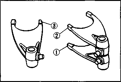
BALANCER SHAFT • When installing the balancer shaft, align the punch marks (® and ©) on the balancer shaft drive gear and driven gear. GEARSHIFT MECHANISM • After installing the countershaft assembly and driveshaft assembly into the right crankcase, fit the gearshift forks ®, © and © into the gearshift fork grooves. ф For 5th (Top) driven gear (No.1) © For 4th driven gear (No.2) © For 3rd drive gear (No.3) NOTE: Three kinds of gearshift forks, © (No. 1), © (No.2) and © (No.3) are used. Carefully examine the illustration for correct installation positions and directions. • Position the gearshift cam, as shown, so that the gearshift fork shafts can be installed easily. NOTE: When replacing the gearshift cam stopper bolt apply a small quantity of THREAD LOCK "1342" to the threaded part of the bolt. tGS) 99000-32050: THREAD LOCK "1342"
^**3,
   • Install the gearshift cam stopper spring. • Install the gearshift cam stopper spring.CRANKCASE When reassembling the crankcase pay attention to the following: • Remove any sealant material on the mating surfaces of the right and left halves of the crankcase and thoroughly remove any oil stains. • Apply SUZUKI BOND N0.1215 uniformly to the mating surface of the left crankcase and assemble the cases within a few minutes. ЦП”] 99000-31110: SUZUKI BOND N0.1215 • Install the dowel pins © in the right crankcase. • Apply engine oil to the conrod big end of the crankshaft and to all of the transmission parts. • Tighten the crankcase bolts to the specified torque. РП Crankcase bolt: 11 N[11]m (1.1 kg-m, 8.0 Ib-ft) • After the crankcase bolts have been tightened, check if the driveshaft and countershaft rotate smoothly. • If the shafts do not rotate smoothly, try to free the shafts by tapping the driveshaft or countershaft with a plastic hammer. CAM DRIVEN GEAR • When installing the gearshift pawls into the cam driven gear, the large shoulder ® must face to the outside, as shown. • When installing the cam guide © and pawl lifter ©, apply a small quantity of THREAD LOCK "1342" to the threaded parts of the securing screws®.
• Properly fit the spring to the gearshift shaft. • Install the gearshift shaft. Align the center teeth of the gear on the gearshift shaft with the center teeth on the cam driven gear, as shown. Install the washer©. NOTE: When replacing the gearshift arm stopper 0, apply a small quantity of THREAD LOCK SUPER "1303" to its threaded part and tighten it to the specified torque. 99000-32030: THREAD LOCK SUPER "1303" Щ Gearshift arm stopper: 19 N»m (1.9 kg-m, 13.5 Ib-ft) • Install the dowel pins (3) and new gasket. • Install the gearshift cover and tighten the bolts diagonally. NOTE: After the gearshift cover and gearshift lever have been installed, make sure that the gears correctly change (while turning the countershaft and driveshaft). If the gears do not change correctly, determine the cause and make the appropriate adjustments. NEUTRAL POSITION INDICATOR SWITCH • Install the neutral position indicator switch spring 0 and switch contact 0. •
• Before mounting the oil pump, apply engine oil to the sliding surfaces of the oil pump body, outer rotor, inner rotor and shaft. • Apply a small quantity of THREAD LOCK "1342" to the oil pump mounting screws. ТЙЭ 99000-32050: THREAD LOCK "1342" • Tighten the oil pump mounting screws. • Install the oil pump idle gear and circlip. CAM CHAIN AND PRIMARY DRIVE GEAR/GENERATOR AND STARTER MOTOR • Install the cam chain. • Fit the key 0 in the key slot on the crankshaft, then install the primary drive gear, concave washer and nut. NOTE: * The sunken side of the concave washer faces the crankcase. * The primary drive gear nut has left-hand threads. • Install the crankcase oil separator 0. [12]
ГОРЯ • Tighten the primary drive gear nut to the specified torque by holding the generator rotor.H Primary drive gear nut: 100 N*m (10.0 kg-m, 72.5 Ib-ft) • Remove the generator rotor bolt, generator rotor, key and starter gear. • Tighten the ring nut to the specified torque with the special tool by holding the primary drive gear nut. 09917-23711: Ring nut socket wrench [4 Ring nut: 80 N*m (8.0 kg-m, 58.0 Ib-ft) • Install the starter gear. • Remove any grease from the tapered portion of the generator rotor and crankshaft. • Install the key (D onto the crankshaft, then install the generator rotor while rotating the starter gear clockwise. After installation, check that the gear turns one direction only. • Apply a small quantity of THREAD LOCK SUPER "1303" to the threaded part of the generator rotor bolt.
И Generator rotor bolt: 160 N[13]m (16.0 kg-m, 115.5 Ib-ft) CLUTCH • Install the thrust washer©. • Install the spacer with the primary driven gear assembly. NOTE: Apply engine oil to both the inside and outside of the spacer. • Install the thrust washer©. * Install the clutch sleeve hub, lock washer © and concave washer. NOTE: * When installing the lock washer ©, align the slit © of the lock washer with the rib of the clutch sleeve hub. * The sunken side of the concave washer faces the crankcase. • Tighten the clutch sleeve hub nut to the specified torque with the special tool. 09920-53740: Clutch sleeve hub holder W Clutch sleeve hub nut: 50 N*m (5.0 kg-m, 36.0 Ib-ft)
W Clutch spring bolt: 10 N»m (1.0 kg-m, 7.0 Ib-ft) • Install the dowel pins and gasket. A CAUTION Use a new gasket to prevent oil leakage. • Engage the teeth of the clutch release rack with those of the clutch release pinion at the clutch cover side, and replace the clutch cover. Make sure that the clutch release rack and clutch release pinion engage positively. To install the clutch cover, tap lightly with a plastic hammer, and tighten the bolts. 0: Gasket • iiS[14]L
•V Ж  PISTON AND CYLINDER PISTON AND CYLINDER
• Position the piston ring gaps, as shown. Before inserting the piston into the cylinder, check that the gaps are properly positioned. • Place a clean rag over the cylinder base to prevent the piston pin circlips from dropping into the crankcase. • Apply a small quantity of SUZUKI MOLY PASTE onto the piston pin. /45[15] *99000-25140: SUZUKI MOLY PASTE • When fitting the piston, the arrow mark 0 on the piston crown points towards the exhaust side. • Install the piston pin circlips with long-nose pliers. A CAUTION Use new piston pin circlips to prevent circlip failure. • Install the cam chain guide. NOTE: A holder for the bottom end of the cam chain guide is cast into the crankcase. Make sure that the cam chain guide 0 is inserted properly. • CYLINDER HEAD • Install the dowel pins 0 and a new gasket. @
Temporarily tighten the cylinder base nuts. • Place the cylinder head onto the cylinder. • The cylinder head bolts and the new gasket must be installed in the correct position, as shown. (A) : 200 mm bolt (B) : 190 mm bolt © : 180 mm bolt NOTE: Before installation, apply engine oil onto the new gasket. • Tighten the cylinder head bolts and nuts to the specified torque. Щ Cylinder head bolt: 38 N*m (3.8 kg-m, 27.5 lb-ft) Cylinder head nut: 25 N*m (2.5 kg-m, 18.0 lb-ft) • After tightening the cylinder head bolts and nuts, tighten the cylinder base nuts to the specified torque.
CAMSHAFT • Turn the crankshaft counterclockwise and align the "T" mark 0 on the generator rotor with the index mark 0 on the crankcase while keeping the cam chain tight. A CAUTION If the crankshaft is turned without drawing the cam chain upward, the cam chain will catch between the crankcase and cam chain drive sprocket. NOTE: Apply grease on the camshaft sprocket locating pin and install the pin into the camshaft. • Engage the cam chain onto the camshaft sprocket with the locating pin hole 0 at two o'clock position. • Fit the camshaft to the camshaft sprocket so that the camshaft sprocket locating pin is inserted into the pin hole of the sprocket. • Make sure that the engraved marks @ on the camshaft are aligned with the upper surface of the cylinder head. NOTE: Do not rotate the generator rotor while doing this. When the sprocket is not positioned correctly, turn only the camshaft sprocket. When installing the camshaft into the camshaft sprocket, do not dislodge the locating pin or it may fall into the crankcase.
• Apply SUZUKI MOLY PASTE to the camshaft journals and cam faces. 99000-25140: SUZUKI MOLY PASTE NOTE: The cam chain tensioner adjuster maintains the proper tension automatically. Before installing the cam chain tensioner adjuster, inspect it for smooth movement. • Remove the cap bolt and turn the cam chain tensioner push rod clockwise until it is locked. Install the cam chain tensioner adjuster onto the cylinder. И Cam chain tensioner bolt 0:10 N*m (1.0 kg-m, 7.0 Ib-ft) • Turn back the cam chain tensioner push rod with the screwdriver to unlock it. Pull out the screwdriver. • Turn the crankshaft counterclockwise to extend the cam chain tensioner. • Tighten the cam chain tensioner adjuster cap bolt®. H Cam chain tensioner adjuster cap bolt ®: 6 N-m (0.6 kg-m, 4.5 Ib-ft) CYLINDER HEAD COVER • Make sure that the mating surfaces of the cylinder head and cylinder head cover are free from moisture, oil, dust and other foreign materials. • Install the dowel pins ф and camshaft end cap ©. • Apply SUZUKI BOND N0.1215 thinly and evenly to the mating surface of the cylinder head cover, and install the cylinder head cover within a few minutes of application.
• Install the gasket ф and cylinder head cover bolts correctly. A CAUTION Use a new gasket to prevent oil leakage. NOTE: When tightening the cylinder head cover bolts, the piston must be at Top Dead Center (TDC) on the compression stroke. • Lightly tighten the cylinder head cover bolts in ascending order, and then securely tighten them with a torque wrench to the specified torque. Щ Cylinder head cover bolt: 10 N*m (1.0 kg-m, 7.0 Ib-ft) • Check and adjust the valve clearance. (Refer to page 2-3.) • Install the valve inspection caps and two spark plugs. NOTE: Apply engine oil lightly to the O-rings. • Install the dowel pin. • Install the gasket and generator cover. A CAUTION Use a new gasket to prevent oil leakage. • Install the oil pipe and tighten the union bolts to the specified torque. И Oil pipe union bolt ©: 23 N*m (2.3 kg-m, 16.5 Ib-ft)
CYLINDER HEAD COVER/ROCKER ARM
CYLINDER HEAD COVER REMOVAL • Drain the engine oil. (Refer to page 2-9) • Remove the front frame covers (right and left). (Refer to page 5-2) • Remove the fuel tank. (Refer to page 4-3) • Remove the clamp and the upper engine mounting bracket 0. • Remove the oil pipe mounting bolts. • Remove the engine protector ®. • Disconnect the spark plug caps and remove the spark plugs. • Remove the valve timing inspection plug © and generator cover cap (4). • Turn the crankshaft counterclockwise and align the "T" mark © on the generator rotor in the middle of the timing inspection hole © on the generator cover. NOTE: Make sure that the piston is at Top Dead Center (TDC) on the compression stroke. • Remove the valve inspection caps and cylinder head cover. (Refer to pages 3-9 and 10.)
A CAUTION Identify the position of each removed part. Organize the parts in their respective groups (i.e., exhaust or intake) so that they can be reinstalled in their original positions. [16] [17]
INSPECTION AND SERVICE CYLINDER HEAD COVER DISTORTION Remove any sealant from the cylinder head cover surfaces. Place the cylinder head cover on a surface plate and check for distortion with a thickness gauge. If the distortion exceeds the limit, replace the cylinder head cover. Service Limit: 0.05 mm (0.002 in) ROCKER ARM SHAFT O.D. Measure the diameter of the rocker arm shaft with micrometer. 09900-20205: Micrometer (0-25 mm) Standard: 11.973-11.984 mm (0.4714-0.4718 in) ROCKER ARM I.D. Measure the inside diameter of the rocker arm and check the camshaft contacting surface for wear. 09900-20605: Dial calipers Standard: 12.000-12.018 mm (0.4724-0.4731 in) ROCKER ARM INSTALLATION Install the rocker arms in the reverse order of removal. Pay attention to the following points: • Apply SUZUKI MOLY PASTE to the rocker arm shafts. Д§»99000-25140: SUZUKI MOLY PASTE • Install the rocker arms and shafts, as shown. • Tighten the rocker arm shaft set bolts 0 to the specified torque. И Rocker arm shaft set bolt 0: 28 N*m (2.8 kg-m, 20.0 Ib-ft) NOTE:
also  пфи пфи   Use a new gasket on each set bolt 0. Use a new gasket on each set bolt 0.CYLINDER HEAD COVER INSTALLATION Install the cylinder head cover in the reverse order of removal. Pay attention to the following points: • Install the cylinder head cover. (Refer to page 3-28.) • Install the oil pipes. A CAUTION Replace the O-ring 0 with a new one to prevent oil leakage. • Tighten the oil pipe securing bolts and union bolt to the specified torque. Щ Oil pipe bolt 10 IVI*m (1.0 kg-m, 7.0 Ib-ft) Oil pipe union bolt 0: 23 N*m (2.3 kg-m, 16.5 Ib-ft) • Tighten the upper engine mounting bracket nuts to the specified torque. Щ Upper engine mounting bracket nut: 40 IM*m (4.0 kg-m, 29.0 Ib-ft)
Ь  to la**? mmm mr to we» 4m# mmNo ишт тшт щ*&нвмшшт нщлшш *»ч .*шшш
3B 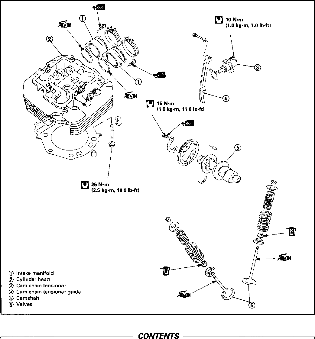 CAMSHAFT/CYLINDER HEAD/VALVES CAMSHAFT/CYLINDER HEAD REMOVAL.... VALVE REMOVAL................................. INSPECTION AND SERVICE..................... VALVE INSTALLATION...........................
3B- 1 3B- 2 3B- 2 3B-10 3B-11 CYLINDER HEAD/CAMSHAFT INSTALLATION
• Remove the carburetor. (Refer to page 4-12.) • Remove the cylinder head cover. (Refer to page 3A-1.) • Remove the oil cooler pipe ф. • Remove the fuel tank rubber damper (2). • Remove the right rear footrest, muffler and exhaust pipe. (Refer to pages 3-2 and 3-3.) • Disconnect the clutch cable by removing the clutch lever. • Remove the camshaft and cylinder head. (Refer to page 3-10.)
1ЕИ1 VALVE REMOVALUsing the special tools, compress the valve spring and remove the valve cotters from the valve stem. 09916-14510: Valve spring compressor 09916-14910: Valve spring compressor attachment 09916-84511: Tweezers • Remove the valve spring retainer, inner spring and outer spring. • Remove the valve from the combustion chamber side. • Remove the oil seal with long-nose pliers. • Remove the spring seat. NOTE: If the valve guides have to be replaced, refer to valve guide servicing on page 3B-6. INSPECTION AND SERVICE CAMSHAFT/AUTOMATIC DE-COMP. ASSEMBLY A CAUTION Do not attempt to disassemble the automatic decomp. assembly. It is not serviceable. AUTOMATIC DE-COMP. Move the automatic de-comp, weight by hand to make sure that it operates smoothly.
ПФЯ CAMSHAFTIf the engine produces abnormal noises, vibrates or lacks power, the camshaft may be distorted or worn to the service limit. The camshaft runout should be checked. Also, check the cams and journals for wear or damage. CAMSHAFT CAM WEAR Worn cams are often the cause of mistimed valve operation resulting in reduced power output. Use a micrometer to measure the cam height (Я). Replace the camshaft if the cams are worn to the service limit. 09900-20202: Micrometer (25-50 mm) Camshaft cam height (A) Service Limit Intake cam: 33.390 mm (1.3146 in) Exhaust cam: 33.380 mm (1.3142 in) CAMSHAFT JOURNAL WEAR Determine whether or not each journal is worn to the service limit by measuring the camshaft journal oil clearance with the camshaft installed in place. Use the plastigauge to measure the clearance. 09900-22301: Plastigauge • Tighten the cylinder head cover bolts evenly and diagonally to the specified torque. NOTE: Make sure that the gasket surface of the cylinder head and cylinder head cover are clean and free of any bond or other material. Do not apply SUZUKI BOND NO. 1207B until after the oil clearance has been determined. [*] Cylinder head cover bolt: 10 N*m (1.0 kg-m, 7.0 Ib-ft) NOTE: Do not rotate the camshaft with the plastigauge in place. Remove the cylinder head cover and read the width of the compressed plastigauge with the envelope scale. This measurement should be taken at the widest part of the compressed plastigauge.
И*И!
21.959-21.980 mm (0.8645-0.8654 in) 17.466-17.484 mm (0.6877-0.6883 in) SEH! If the camshaft journal oil clearance exceeds the service limit, measure the outside diameter of the camshaft. Replace either the cylinder head or the camshaft if the clearance is incorrect.09900-20205: Micrometer (0-25 mm) Camshaft journal O.D.: (Right & Center) Camshaft journal O.D.: (Left) CAMSHAFT RUNOUT Measure the runout with a dial gauge. Replace the camshaft if the runout exceeds the service limit. 09900-20701: Magnetic stand 09900-20606: Dial gauge (1/100 mm) 09900-21304: V-block Service Limit: 0.10 mm (0.004 in) CYLINDER HEAD DISTORTION Decarbonize the combustion chamber. Check the gasket surface of the cylinder head for distortion. Use a straightedge and thickness gauge. Take clearance readings at several places. Replace the cylinder head if the readings exceed the service limit. Service Limit: 0.05 mm (0.002 in) VALVE FACE WEAR Measure the valve face ©. If it is out of specification, replace the valve with a new one. NOTE: Visually inspect each valve face for wear. Replace any valve with an abnormally worn face. Service Limit: 0.5 mm (0.02 in) VALVE STEM RUNOUT Check the valve stem runout with a dial gauge. Replace the valve if the runout exceeds the service limit. 09900-20701: Magnetic stand 09900-20606: Dial gauge (1/100 mm) 09900-21304: V-block (100 mm)
VALVE HEAD RADIAL RUNOUT Place the dial gauge at a right angle to the valve head face and measure the valve head radial runout. Replace the valve if it measures more than the service limit. Service Limit: 0.03 mm (0.001 in) ЕРИ 09900-20701: Magnetic stand Service Limit Intake and exhaust valves: 0.35 mm (0.014 in) И-РЯ 09900-20205: Micrometer (0-25 mm) Standard IN.: 5.475-5.490 mm (0.2156-0.2161 in) EX.: 5.455-5.470 mm (0.2148-0.2154 in) Pi VALVE STEM WEAR Measure the valve stem O.D. If it is out of specification, replace the valve with a new one. If the valve stem O.D. is within specification, but the valve stem deflection is not, replace the valve guide. After replacing the valve or valve guide, recheck the clearance. 09900-20606: Dial gauge (1/100 mm) VALVE STEM DEFLECTION Lift the valve about 10 mm (0.39 in) off the valve seat. Measure the valve stem deflection in two directions, "X" and "Y", perpendicular to each other. Position the dial gauge, as shown. If the deflection exceeds the service limit, determine whether the valve or the guide should be replaced with a new one.   
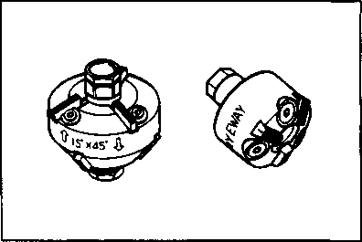
ИФЯ ffiHS VALVE GUIDE SERVICINGUsing the valve guide remover, drive the valve guide out toward the camshaft side. 09916-44910: Valve guide remover/installer NOTE: * Discard the removed valve guide subassemblies. * Only oversized valve guides are available as replacement parts. (Part No. Ill 15-32E70.) • Re-finish the valve guide holes in the cylinder head with the reamer 0 and handle (2). 09916-34580: Valve guide reamer 09916-34542: Reamer handle • Fit a ring to each valve guide. Be sure to use new rings and valve guides. • Oil the stem hole of each valve guide and drive the guide into the guide hole with the valve guide installer. 09916-44910: Valve guide remover/installer A CAUTION Failure to oil the valve guide hole before driving the new guide into place may result in a damaged guide or head. • After fitting the valve guides, re-finish their bores with the reamer ® and handle 0. Be sure to clean and oil the guides after reaming. 09916-34550: Valve guide reamer 09916-34542: Reamer handle VALVE SEAT WIDTH • Coat the valve seat uniformly with Prussian blue. Install the valve and attach a valve lapper onto it. Tap the coated seat with the valve face in a rotating manner, in order to obtain a clear impression of the seating contact. • Standard Valve seat width @>: 0.9-1.1 mm (0.035-0.043 in) If the valve seat is out of specification, re-cut the seat. VALVE SEAT SERVICING The valve seats for both the intake and exhaust valves are machined to two different angles. The seat contact surface is cut at 45°. INTAKE EXHAUST 45° N-626 45° N-229 30° N-626 15° N-229 SEKI 09916-24900: Valve seat cutter set 09916-24810: Valve seat cutter (N-626) 09916-27720: Valve seat cutter (N-229) 09916-24480: Solid pilot (N-140-5.5)
NOTE:
INTAKE
EXHAUST
 The valve seat contact area must be inspected after each cut. * When installing the solid pilot, rotate it slightly. Seat the pilot snugly. Install the 45° cutter and T-handle. * Using the 45° cutter, descale and clean up the seat. Rotate the cutter one or two turns. * Inspect the valve seat width after every cut. If the valve seat is pitted or burned, use the 45° cutter to condition the seat some more. NOTE:
If the contact area is too high on the valve, or if it is too wide, use the 30° cutter (for the intake side) and the 15° cutter (for the exhaust side) to lower and narrow the contact area. If the contact area is too low or too narrow, use the 45° cutter to raise and widen the contact area. • After the desired seat position and width is achieved, use the 45° cutter very lightly to clean up any burrs caused by the previous cutting operations. A caution] DO NOT use lapping compound after the final cut is made. The finished valve seat should have a velvety smooth finish and not a highly polished or shiny finish. This will provide a soft surface for the final seating of the valve which will occur during the first few seconds of engine operation. • Clean and assemble the cylinder head and valve components. Fill the intake and exhaust ports with gasoline to check for leaks. If any leaks occur, inspect the valve seat and face for burrs or other things that could prevent the valve from sealing. A WARNING Always use extreme caution when handling gasoline. NOTE:
JEHJ VALVE STEM END CONDITIONInspect the valve stem end face for pitting and wear. If pitting or wear of the valve stem end face are present, the valve stem end should be resurfaced, providing that the length ф will not be reduced to less than 2.7 mm (0.11 in). If this length becomes less than 2.7 mm (0.11 in), the valve should be replaced. After installing a valve whose stem end has been resurfaced as above, check to ensure that the face (2) of the valve stem end is above the cotters (3). VALVE SPRING The force of the coil spring keeps the valve seat tight. A weakened spring results in reduced engine power output and accounts for the chattering noise coming from the valve mechanism. Check the valve springs for proper strength by measuring their free length and also by the force required to compress them. If the spring length is less than the service limit or if the force required to compress the spring does not fall within the range specified, replace both the inner and outer springs as a set. 09900-20102: Vernier calipers Valve spring free length Service Limit INNER: 34.4 mm (1.35 in) OUTER: 38.1 mm (1.50 in) Valve spring tension Standard
ЕЕИ1  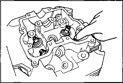  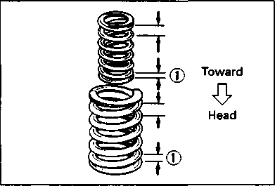  VALVE INSTALLATION VALVE INSTALLATION
• Install the valve spring seat 0. Be careful not to confuse the lower seat with the spring retainer®. • Lubricate each oil seal with oil and fit the seals onto each guide. Be sure to oil each oil seal lip. A CAUTION- Do not reuse the oil seals. • Insert the valves, with their stems coated with high quality molybdenum disulfide lubricant (SUZUKI MOLY PASTE). Coat the entire stem making sure that there are no gaps. £§JH 99000-25140: SUZUKI MOLY PASTE A CAUTION When inserting each valve, take care not to damage the lip of the oil seal. • Install the valve springs with the smaller pitch ф facing the cylinder head. [18] A CAUTION Be sure to install all of the parts in their original positions. CYLINDER HEAD/CAMSHAFT INSTALLATION Install the cylinder head and camshaft in the reverse order of removal. Pay attention to the following points: • Replace the О-rings with new ones when removing the intake manifolds. NOTE: • Apply SUZUKI SUPER GREASE "A" to the O-rings. Д§Н99000-25010: SUZUKI SUPER GREASE "A" • Install the intake manifold so that the "1Д"тагк (left side)/"2A" mark (right side) faces upward. • Install the cam chain tensioner. • Install the camshaft and cylinder head. (Refer to pages 3-26 and 3-27.) • Install the cylinder head cover. (Refer to page 3-28.) • Install the oil cooler pipe. A CAUTION Replace the O-ring 0 with a new one to prevent oil leakage. • Tighten the oil pipe securing bolts to the specified torque.
CYLINDER/PISTON
CYLINDER/PISTON REMOVAL • (Refer to page 3A-1.) • Remove the camshaft and cylinder head. (Refer to page 3B-1.) • Remove the cylinder and piston. (Refer to page 3-11.) INSPECTION AND SERVICE CYLINDER DISTORTION Check the gasket surface of the cylinder for distortion. Use a straightedge and thickness gauge. Take clearance readings at several places. If any clearance readings exceed the service limit, replace the cylinder. Service Limit: 0.05 mm (0.002 in) CYLINDER BORE Inspect the cylinder wall for nicks, scratches or other damage.
НФЯ 09900-20508: Cylinder bore gauge set09900-20513: Gauge rod Standard: 100.000-100.015 mm (3.9370-3.9376 in) PISTON DIAMETER Measure the piston diameter with a micrometer at 21 mm (0.8 in) from the skirt end. If the piston diameter is less than the service limit, replace the piston. ЕН*П 09900-20204: Micrometer (75-100 mm) Service Limit: 99.880 mm (3.9323 in) PISTON-CYLINDER CLEARANCE Subtract the piston diameter from the cylinder bore diameter. If the piston to cylinder clearance exceeds the service limit replace both cylinder and piston. Service Limit: 0.120 mm (0.0047 in) PISTON RING-GROOVE CLEARANCE
If any of the measurements exceed the service limit, replace both the piston and piston rings. @ 09900-20803: Thickness gauge 09900-20205: Micrometer (0-25 mm) Piston ring-groove clearance Service Limit 1st: 0.180 mm (0.0071 in) 2nd: 0.150 mm (0.0059 in) Piston ring groove width Standard 1st: 1.23-1.25 mm (0.048-0.049 in) 2nd: 1.21-1.23 mm (0.047-0.048 in) Oil: 2.81-2.83 mm (0.110-0.111 in) Piston ring thickness Standard 1st: 1.170-1.190 mm (0.0461-0.0469 in) 2nd: 1.150-1.170 mm (0.0453-0.0461 in) NOTE: Using a soft-metal scraper, decarbon the crown of the piston and the piston ring grooves. PISTON RING FREE END GAP AND PISTON RING END GAP Use vernier calipers to measure the piston ring free end gap. Next, fit the piston ring squarely into the cylinder and measure the piston ring end gap with a thickness gauge. If any of the measurements exceed the service limit, replace the piston ring with a new one. 09900-20102: Vernier calipers Piston ring free end gap Service Limit 1st: 10.8 mm (0.43 in) 2nd: 9.1 mm (0.36 in)
U!M! 09900-20803: Thickness gaugePiston ring end gap Service Limit 1st: 0.50 mm (0.020 in) 2nd: 1.00 mm (0.039 in) PISTON PIN AND PIN BORE
09900-20605: Dial calipers 09900-20205: Micrometer (0-25 mm) Piston pin bore Service Limit: 23.030 mm (0.9067 in) Piston pin O.D. Service Limit: 22.980 mm (0.9047 in) PISTON/CYLINDER INSTALLATION Install the piston and cylinder in the reverse order of removal. Pay attention to the following points: OIL RING
TOP RING AND 2ND RING The top ring and 2nd ring have different ring face shapes. The top ring and 2nd ring have either "R" or "RN" marked on the side. The piston rings should be installed with the mark facing up. Position the gaps of the three rings as shown in the illustration. (Refer to page 3C-0.) Before inserting the piston into the cylinder, check that the gaps are located correctly. • Install the piston and cylinder head. (Refer to page 3-25.) Install the spacer 0 into the oil ring groove first. Then install both side rails 0, one on each side of the spacer. The spacer and side rails do not have a specific top or bottom when they are new. When reassembling used parts, install them in their original place and direction.
Г11 19 N*m (1.9 kg-m, 13.5 Ib-ft) 160 N-m (16.0 kg-m, 115.5 Ib-ft) © Gearshift shaft © Cam driven gear © Starter torque limiter 0 Starter idle gear © Starter clutch © Generator rotor 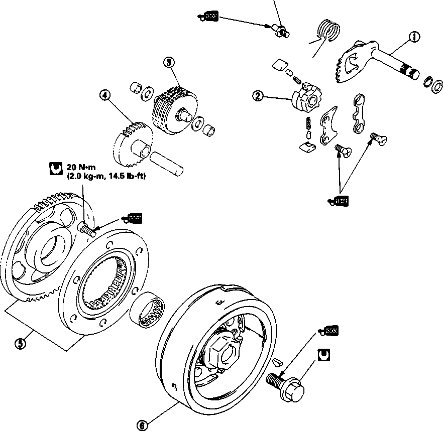 STARTER MOTOR/GENERATOR ROTOR/GEARSHIFT -------------------------------- CONTENTS ------------------------------ STARTER MOTOR REMOVAL....................................................... 3D-1 GENERATOR ROTOR REMOVAL................................................... 3D-1 GEARSHIFT SHAFT REMOVAL .................................................... 3D-2 INSPECTION AND SERVICE......................................... 3D-2 GENERATOR ROTOR INSTALLATION............................................. 3D-3 GEARSHIFT SHAFT INSTALLATION............................................... 3D-3 STARTER MOTOR INSTALLATION................................................. 3D-3 STARTER MOTOR REMOVAL • (Refer to pages 5-2 and 5-4.) • Remove the right rear footrest, muffler and exhaust pipe. (Refer to pages 3-2 and 3-3.) • Disconnect the clutch cable by removing the clutch lever. • Remove the oil pipe by removing the bolts. • Remove the cam chain tensioner. • Disconnect the starter motor lead wire ©. • Remove the clutch cable holder (£) and starter motor (3). • Disassemble the starter motor. (Refer to page 6-13.) GENERATOR ROTOR REMOVAL • Drain the engine oil. (Refer to page 3-2.) • Remove the engine protector. • Remove the left front footrest and gearshift pedal. (Refer to page 3-3.) • Remove the generator cover. • Remove the starter torque limiter, starter idle gear, generator rotor and starter gear. (Refer to pages 3-12 and 3- 13.) [19] GEARSHIFT SHAFT REMOVAL • Remove the left front footrest, engine sprocket cover and gearshift pedal. (Refer to page 3-3.) • Remove the gearshift cover. • Remove the gearshift shaft 0 and remove the cam driven gear 0 by removing the screws ®. NOTE: When removing the cam driven gear, do not lose the gearshift pawls 0, pins © and springs ©. INSPECTION AND SERVICE STARTER CLUTCH Inspect the stater clutch for wear or damage. STARTER TORQUE LIMITER A CAUTION Do not attempt to disassemble the starter toque lim iter. It is not serviceable. Check the slip torque of the starter torque limiter. Slip torque: 42-64 N*m (4.2-6.4 kg-m, 30.5-46.5 Ib-ft)
SEPH 09930-73110: Starter torque limiter holder09930-73120: Starter torque limiter holder Attach the starter torque limiter and the special tools into the vise, as shown. If the slip torque limiter is not within specification, replace the starter torque limiter with a new one. GENERATOR ROTOR INSTALLATION
• Apply THREAD LOCK SUPER "1303" to the bolts and tighten them to the specified torque. гШ 99000-32030: THREAD LOCK SUPER "1303" И Bolt: 25 N*m (2.5 kg-m, 18.0 Ib-ft) Check that the generator rotor ® turns in the direction of the arrow mark © while holding the starter gear. The generator rotor should never turn in the opposite direction of the arrow mark. • Install the generator rotor. (Refer to page 3-21.) • Install the dowel pin. A CAUTION Use a new gasket to prevent oil leakage. • Install the generator cover. GEARSHIFT SHAFT INSTALLATION Install the gearshift shaft in the reverse order of removal. (Refer to page 3-20.) STARTER MOTOR INSTALLTION Install the starter motor in the reverse order of removal. (3=/* <T -
CLUTCH ф Clutch release arm © Clutch release pinion © Clutch release rack @ Clutch pressure plate © Clutch sleeve hub © Washer seat ® Concave washer © Clutch driven plate No.2 (Thicker plate, 1 pc) © Stopper ring ® Clutch drive plate No.2 (1 pc) © Clutch driven plate No.1 (7 pc) © Clutch drive plate No.1 (7 pc) © Primary driven gear ass'y  is properly installed. 3E  CONTENTS CLUTCH REMOVAL................................................................... 3E-1 INSPECTION AND SERVICE......................................................... 3E-2 CLUTCH INSTALLATION............................................................. 3E-3 CLUTCH REMOVAL • Drain the engine oil (Refer to page 2-9.) • Remove the right rear frame cover. (Refer to page 5-4.) • Remove the right rear footrest, muffler and exhaust pipe. (Refer to pages 3-2 and 3-3.) • Remove the right front footrest and rear brake pedal. (Refer to page 3-4.) • Disconnect the clutch cable at the clutch cable lever. (Refer to page 3-4.) • Remove the engine protector. (Refer to page 3-2.) • • Remove the clutch cover.
• Remove all of the clutch parts. (Refer to page 3-11.) 
1№I*
(EM! INSPECTION AND SERVICECLUTCH DRIVE PLATE Measure the thickness of each drive plate with vernier calipers. Replace any drive plates that are worn to the service limit. 09900-20102: Vernier calipers Standard Thickness No.1 & No.2: 2.9-3.1 mm (0.11-0.12 in) Service Limit Thickness No.1 & No.2: 2.6 mm (0.10 in) CLUTCH DRIVEN PLATE Measure each driven plate for distortion with a thickness gauge. Replace any driven plates which exceed the service limit. 09900-20803: Thickness gauge Service Limit: 0.1 mm (0.004 in) CLUTCH SPRING FREE LENGTH Measure the free length of each clutch spring with vernier calipers. If any spring is not within the service limit, replace all of the springs. 09900-20102: Vernier calipers
Inspect the clutch release bearing for any abnormality; especially cracks. When removing the bearing from the clutch, decide whether it can be reused or if it should be replaced. Smooth engagement and disengagement of the clutch depends on the condition of this bearing. CLUTCH RELEASE PINION AND RACK Rotate the clutch release pinion by hand to inspect for smooth rotation. If a large resistance is felt when rotating it, inspect the pinion and rack for damage or wear. If any damage or wear is found, replace them as a set. CLUTCH INSTALLATION Install the clutch in the reverse order of removal. Pay attention to the following points: • Install all of the clutch parts. (Refer to page 3-23.)
ф 1st (low) driven gear © 5th (Top) driven gear © 3rd driven gear © 4th driven gear © 2nd driven gear © Driveshaft © Counters haft/1st (low) drive gear © 5th (Top) drive gear © 3rd drive gear ® 4th drive gear © 2nd drive gear © Gearshift cam stopper © Gearshift cam stopper plate © Gearshift cam © Gearshift fork No. 1 © Gearshift fork No. 2 © Gearshift fork No. 3  3F GEARSHIFT CAM/TRAIMSMISSIOIM CONTENTS GEARSHIFT CAM/TRANSMISSION REMOVAL................... 3F-1 INSPECTION AND SERVICE......................................................... 3F-1 TRANSMISSION/GEARSHIFT CAM INSTALLATION............................. 3F-2 GEARSHIFT CAM/TRANSMISSION REMOVAL • Remove the engine. (Refer to pages 3-2 to 3-5.) • Separate the left and right crankcases. (Refer to pages 3-9 to 3-15.) • Remove the gearshift cam, driveshaft assembly and countershaft assembly. (Refer to page 3-16.) 2ND DRIVE GEAR DISASSEMBLY • Remove the 2nd drive gear by using the gear puller and appropriate attachment. 09913-60910: Gear puller INSPECTION AND SERVICE GEARSHIFT FORK GROOVE CLEARANCE Measure the gearshift fork clearance in the groove of its respective gear with the thickness gauge. If the clearance exceeds the specification, replace the fork, its respective gear or both. The clearance for each of the three gearshift forks plays an important role in the smoothness and positiveness of the shifting action. Gearshift fork groove clearance Standard: 0.10-0.30 mm (0.004-0.012 in) Service Limit: 0.50 mm (0.020 in)
ВгИ! 09900-20803: Thickness gauge 09900-20102: Vernier calipersShift fork groove width Standard: 5.0-5.1 mm (0.197-0.200 in) Shift fork thickness Standard: 4.8-4.Э mm (0.189-0.193 in) TRANSMISSION/GEARSHIFT CAM INSTALLATION Assemble the countershaft and driveshaft assemblies in the reverse order of disassembly. Pay attention to the following points: NOTE: Before installing the gears, lightly coat the driveshaft and countershaft with moly paste or engine oil. Д§Н 99000-25140: SUZUKI MOLY PASTE • A CAUTION * Never reuse a circlip. After a circlip has been removed from a shaft, it should be discarded, and a new circlip must be installed. * When installing a new circlip, do not expand the end gap larger than required to slip the circlip over the shaft. * After installing a circlip, make sure that it is completely seated in its groove and securely fitted. [20] [21] NOTE: When reassembling the transmission, attention must be given to the locations and positions of the washers and circlips. The cross sectional view shows the correct position of the gears, washers and circlips.
80 N*m (8.0 kg-m, 58.0 Ib-ft) © Crankshaft (left half) © Crankshaft bearing nut © Balancer shaft 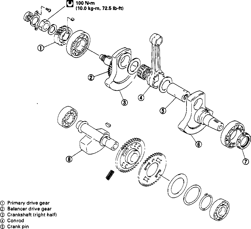 CONTENTS BALANCER SHAFT/CRANKSHAFT/CRANKCASE BALANCER SHAFT/CRANKSHAFT/CRANKCASE REMOVAL 3G-1 BALANCER SHAFT DISASSEMBLY............................................... 3G-1 CRANKSHAFT DISASSEMBLY..................................................... 3G-1 INSPECTION AND SERVICE......................................................... 3G-1 CRANKSHAFT ASSEMBLY.......................................................... 3G-3 BALANCER SHAFT ASSEMBLY................................................... 3G-3 CRANKCASE/CRANKSHAFT/BALANCER SHAFT INSTALLATION......... 3G-4 BALANCER SHAFT/CRANKSHAFT/ CRANKCASE REMOVAL • Remove the engine. (Refer to pages 3-2 to 3-5.) • Separate the left and right crankcases. (Refer to pages 3-9 to 3-15.) • Remove the driveshaft and countershaft assemblies. (Refer to page 3-16.) • Remove the balancer shaft and crankshaft. (Refer to page 3-16.) BALANCER SHAFT DISASSEMBLY • Removet the circlip 0 and washers (0, ®).
CRANKSHAFT DISASSEMBLY Refer to page 3G-0. INSPECTION AND SERVICE CONROD SMALL END I.D. Using dial calipers, measure the conrod small end inside diameter. 09900-20605: Dial calipers
CONROD DEFLECTION AND CONROD BIG END SIDE CLEARANCE Wear on the big end of the conrod can be estimated by checking the movement of the small end of the conrod. This method can also check the extent of wear on the con- rod's big end parts. 09900-20701: Magnetic stand 09900-20606: Dial gauge (1/100 mm) 09900-21304: V-block Service Limit: 3.0 mm (0.12 in) Push the big end of the conrod to one side and measure the side clearance with a thickness gauge. CRANKSHAFT RUNOUT Support the crankshaft with "V" blocks, as shown. Position the dial gauge, as shown, and slowly rotate the crankshaft to read the runout. Correct or replace the crankshaft if the runout is greater than the service limit. BALANCER SHAFT Inspect the balancer shaft for wear or damage. 11ГМ! 09900-20606: Dial gauge (1/100 mm) 09900-20701: Magnetic stand 09900-21304: V-block (100 mm) Service Limit: 0.05 mm (0.002 in) 11ГМ! 09900-20803: Thickness gauge Service Limit: 1.00 mm (0.039 in) If the measurements exceed the service limit, reduce the deflection and side clearance by replacing any worn parts (e.g., conrod, big end bearing and crank pin, etc.) or replace the crankshaft. 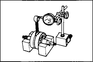  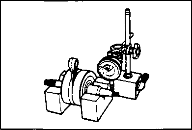 
Inspect the play of the crankcase bearings while they are mounted in the left and right crankcase. Turn the inner race by hand and check to see that it turns smoothly. If it does not turn quietly and smoothly, the bearing is defective and must be replaced with a new one. NOTE: When reassembling the bearing retainer 0, apply a small quantity of THREAD LOCK "1342" to the bearing retainer screws and bolts. CRANKSHAFT ASSEMBLY Assemble the crankshaft in the reverse order of disassembly. Pay attention to the following points: • When rebuilding the crankshaft, the width between the webs should be within the specified range. STD width between webs: 71.0 ± 0.1 mm (2.795 ± 0.004 in) BALANCER SHAFT ASSEMBLY • Align the two holes when installing the balancer driven gear. NOTE: The chamfer side of the No.2 balancer driven gear should face another gear. [22] • Install washers ©&© and circlip ф. NOTE:
■CD  The sunken side of the concave washer © should face the balancer driven gear. The sunken side of the concave washer © should face the balancer driven gear.
• When installing the balancer shaft, align the punch marks on the balancer drive gear and balancer driven gear. (Refer to page 3-18.) CRANKCASE/CRANKSHAFT/BALANCER SHAFT INSTALLATION Install the crankcase, crankshaft and balancer shaft in the following order: QBalancer shaft ©Crankshaft ©Transmission ©Crankcase ENGINE LUBRICATION SYSTEM
OIL FILTER • • Remove the oil filter 0. • Install the new oil filter. NOTE: Before installing the oil filter and oil filter cap, check to make sure that the spring (2) and new О-rings I® and ®) are installed correctly.
REMOVAL AND DISASSEMBLY • Remove the clutch. (Refer to page 3-11.) • Remove the oil pump idle gear and oil pump. (Refer to page 3-14.) • Remove the oil pump driven gear by removing the circlip. 09900-06107: Snap ring pliers [23]
И-Н! • Remove the rotor shaft 0, drive pin 0, inner rotor 0 and outer rotor 0 from the oil pump body 0.INSPECTION Inspect the rotor tip clearance and outer rotor clearance with a thickness gauge. If the clearance exceeds the service limit, replace the oil pump with a new one. 09900-20803: Thickness gauge Rotor tip clearance Service Limit: 0.20 mm (0.008 in) Outer rotor clearance Service Limit: 0.35 mm (0.014 in). ASSEMBLY AND INSTALLATION Assemble and install the oil pump in the reverse order of removal and disassembly. Pay attention to the following points: A CAUTION Wash the oil pump with fresh engine oil before reassembly • When installing the outer rotor and inner rotor into the oil pump body, be sure the punch marks on the inner and outer rotors face inward. • • Apply a small quantity of THREAD LOCK "1342" to the screw and tighten it. 99000-32050: THREAD LOCK "1342" • Install the washer, pin, oil pump driven gear and washer. • Fasten the oil pump driven gear with the circlip. 09900-06107: Snap ring pliers NOTE: * The bulge of the oil pump driven gear should face outside. * After installing the oil pump driven gear, rotate the gear by hand to see if it turns smoothly. * Apply a small quantity of THREAD LOCK "1342“ to the screws and then install the oil pump onto the engine. 99000-32050: THREAD LOCK "1342" OIL NOZZLE AND OIL JET REMOVAL • Remove the engine. (Refer to pages 3-2 to 3-5.) • Separate the left and right crankcases. (Refer to pages 3-9 to 3-15.) • Remove the driveshaft and countershaft assemblies and the crankshaft. (Refer to page 3-16.) • Remove the oil nozzle ф and oil jet @ from the right crankcase. A CAUTION
INSPECTION Check the oil nozzle for damage or clogs. REASSEMBLY • Install the new oil jet (D, as shown in the illustration. • Install the oil nozzle 0. • Apply THREAD LOCK SUPER "1303" to the bolt and tighten to the specified torque. 99000-32030: THREAD LOCK SUPER "1303" H Bolt: 10 N*m (1.0 kg-m, 7.0 Ib-ft) OIL SUMP FILTER REMOVAL • Remove the engine. (Refer to pages 3-2 to 3-5.) • Separate the left and right crankcases. (Refer to pages 3-9 to 3-15.) • Remove the oil sump filter cover 0. • Remove the oil sump filter @. INSPECTION Check the oil sump filter for any damage or clogs. INSTALLATION Install the oil sump filter in the reverse order of removal. Pay attention to the following points:
FUEL AND LUBRICATION SYSTEM --------------------------- CONTENTS--------------------------- FUEL SYSTEM.......................................................... 4- 1 FUEL VALVE............................................................ 4-2 FUEL TANK............................................................. 4-3 CARBURETOR ........................................................ 4- 5 CONSTRUCTION....................................................... 4-5 SPECIFICATIONS...................................................... 4- 6 I.D. NO. LOCATION..................................................... 4- 6 SLOW SYSTEM......................................................... 4- 7 MAIN SYSTEM.......................................................... 4-8 DIAPHRAGM AND PISTON OPERATION.......................... 4- 9 PISTON VALVE LIFT CONTROL SYSTEM......................... 4-10 STARTER SYSTEM.................................................... 4-11 FLOAT SYSTEM........................................................ 4-11 REMOVAL............................................................... 4-12 DISASSEMBLY......................................................... 4-13 CARBURETOR CLEANING.......................................... 4-16 INSPECTION............................................................ 4-18 NEEDLE VALVE INSPECTION...................................... 4-18 FLOAT HEIGHT ADJUSTMENT..................................... 4-18 SOLENOID VALVE INSPECTION.................................... 4-18 V T V INSPECTION..................................................... 4-19 THROTTLE POSITION SENSOR INSPECTION................... 4-19 REASSEMBLY AND REMOUNTING................................ 4-19 CARBURETOR SYNCHRONIZATION ............................. 4-22 LUBRICATION SYSTEM AND COOLING SYSTEM............... 4-24 ENGINE LUBRICATION/CYLINDER HEAD COOLING SYSTEM CHART.......................................... 4-25 OIL COOLER............................................................ 4-27 топливно-смазочная система ................................................................................................................... ОГЛАВЛЕНИЕ ТОПЛИВНОЙ СИСТЕМЫ 4 - 1 топливный клапан 4-2 топливный бак 4-3 Карбюраторный 4 - 5 строительство 4-5 Технические характеристики 4 - 6 Удостоверения личности нет. Расположение 4 - 6 МЕДЛЕННАЯ СИСТЕМА 4 - 7 основная система 4-8 ДИАФРАГМЫ И ЭКСПЛУАТАЦИЯ ПОРШЕНЬ 4 - 9 поршневой клапан Система управления подъемом 4-10 система стартера 4-11 плавающая система 4-11 Удаление 4-12 разборка 4-13 чистка карбюратора 4-16 осмотр 4-18 осмотр игольчатого клапана 4-18 Регулировка высоты поплавка 4-18 осмотр электромагнитного клапана 4-18 Осмотр 4-19 V T V Осмотр датчика положения дроссельной заслонки 4-19 МОНТАЖ И ПЕРЕМОНТАЖ 4-19 синхронизация карбюратора 4-22 Система смазки и система охлаждения 4-24 Смазка двигателя / головка цилиндра Диаграмма 4-25 системы охлаждения масляный охладитель 4-27FUEL и система смазки FUEL SYSTEM When turning starter motor, negative pressure is generated in the combustion chamber. This negative pressure works on the diaphragm of fuel valve through passage way provided in the carburetor main bore and vacuum hose, and diaphragm builds up a negative pressure which is higher than the spring pressure. Valve in the fuel valve is forced to open due to diaphragm operation, and thus allows fuel to flow into carburetor float chamber. ТОПЛИВНАЯ СИСТЕМА При вращении стартера в камере сгорания генерируется отрицательное давление. Это отрицательное давление работает на мембрану топливного клапана через путь прохождения, предусмотренный в карбюраторе основного отверстия и вакуумного шланга, а мембрана накапливает отрицательное давление, которое выше давления пружины. Клапан в топливном клапане вынужден открываться из-за работы мембраны, и таким образом позволяет топливу поступать в карбюраторную поплавковую камеру.
FUEL VALVE MECHANISM A valve is provided at the end of the fuel valve lever and can switch over to "ON", "PRI" and "RES".
FUEL VALVE ТОПЛИВНЫЙ КЛАПАН FUEL VALVE/FUEL FILTER REMOVAL • Remove the seat. • Remove the fuel tank. (Refer to page 4-3.) • Remove the fuel valve by removing the mounting bolts. топливный клапан/топливный фильтр Удаление • * Снимите сиденье. • • Снять топливный бак. (См. стр. 4-3.) • * Снимите топливный клапан, сняв крепежные болты. • ПРЕДУПРЕЖДЕНИЕ
Gasoline is very explosive. Extreme care must be taken. Gaskets and О-ring must be replaced with new ones to prevent fuel leakage.  A WARNING A WARNINGINSPECTION AND CLEANING
FUEL TANK FUEL TANK REMOVAL Remove the seat. Remove the front frame covers (right and left). Топливный бак снятие топливного бака Снимите сиденье. Снимите передние крышки рамы (справа и слева). • Turn the fuel valve to "ON" position. • Disconnect the fuel hose ф and vacuum hose @. AWARNING Gasoline is very explosive. Extreme care must be taken. [24]
• Remove the fuel tank mounting bolts. • Disconnect the fuel tank drain hose. • Remove the fuel tank. • Disconnect the fuel gauge lead wire coupler.  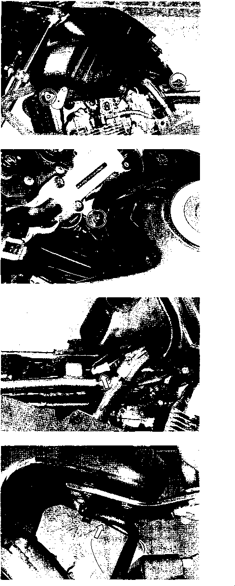
CARBURETOR CONSTRUCTION @ Pilot jet @ O-ring © Needle jet @ Jet holder © Main jet @ O-ring @ Washer @ Spring © Pilot screw © Float © Float pin © © O-ring Float chamber Drain screw Solenoid valve V.T.V. (Vacuum Transmitting Valve) Throttle position sensor Lift control valve body Spring Spring retainer Spacer Diaphragm © Top cap © Spring © Jet needle stopper © O-ring © Spring © E-ring ® Washer ©Jet needle © Diaphragm ® Piston valve © Main air jet © Starter plunger © Spring © O-ring © Vacuum chamber © Spring © Throttle stop screw ® O-ring © Valve seat (fo) Needle valve 
COUNTRY OR AREA E-02: U.K. E-04: France E-17: Sweden E-18: Switzerland E-22: Germany E-24: Australia E-25: Netherlands E-34: Italy E-37: Brazil SPECIFICATIONS
SPECIFICATION ITEM
E-02, 04, 17, 22, 24, 25, 34 E-18 U-type E-22 E-37 Carburetor type MIKUNI BSR32SS - - - Bore size 32 mm — — — I.D. No. 04F0 04F1 04F3 04F4 Idle r/min. 1 500 ±100 r/min. 1 500 ±50 r/min. 1 500 ±100 r/min. - Float height 13.0 ± 1.0 mm (0.51+0.04 in) - - - Main jet (M.J.) #115 — — — Jet needle (J.N.) 5DH23-53-3rd — — — Needle jet (N.J.) P-0 — — — Throttle valve (Th.V.) #90 — — — Pilot jet (P.J.) #20 — — — Starter jet (G.S.) #57.5 — — #62.5 Pilot screw (P.S.) PRE-SET (3 turns back) - - - Throttle cable play (pulling cable) 0.5-1.0 mm (0.02-0.04 in) - - - Choke cable play 0.5-1.0 mm (0.02-0.04 in) - - -
Each carburetor has I.D. Number ф printed on the carburetor body according to its specification. SLOW SYSTEM This system supplies fuel during engine operation with throttle valve 1 closed or slight opened. The fuel from float chamber 2 is metered by pilot jet 3 where it mixes with air coming in through pilot air jet 4. This mixture, rich with fuel, then goes up through pilot passage to pilot screw 5. A part of the mixture is discharged into the main bore out of bypass ports 6. The remainder of mixture is metered by pilot screw 5. and sprayed out into the main bore through pilot outlet 7. СИСТЕМА ХОЛОСТОГО ХОДА
MAIN SYSTEM As throttle valve 1 is opened, engine speed rises, and this increases negative pressure in the venture А. Consequently the piston valve 2 moves upward. Meanwhile, the fuel in float chamber 3 is metered by main jet 4, and the metered fuel enters needle jet 5, in which it mixes with the air admitted through main air jet 6 to form an emulsion. The emulsified fuel then passes through the clearance between needle jet 5 and jet needle 7, and is discharged into the venture А, in which it meets main air stream being drawn by the engine. Mixture proportioning is accomplished in needle jet 5; the clearance through which the emulsified fuel must flow in large or small, depending ultimately on throttle position. ОСНОВНАЯ СИСТЕМА По мере открытия дроссельной заслонки 1 обороты двигателя повышается, а это увеличивает отрицательное давление (разряжение) в смесительной камере А и на мембране дросселя 2. Следовательно, дроссель 2 перемещается вверх. Между тем, топливо в поплавковой камере 3 дозируется главным топливным жиклёром 4, и затем топливо попадает в распылительную трубку 5, в которой смешивается с воздухом, пропущенным через главные воздушный жиклёр 6 для приготовления эмульсии. Топливная эмульсия после этого проходит через зазор между распылительной трубкой 5 и дозирующей иглой 7, и попадает в смесительную камеру А, в котором оно встречает главный поток воздуха с которым и попадает в двигатель. Количество топливной смеси попавшей в смесительную камеру А зависит в конечном итоге от положения иглы, дросселя и дроссельной заслонки.
DIAPHRAGM AND PISTON OPERATION The carburetor is a variable-venturi type. The venturi cross section area of carburetor is increased or decreased automatically by the piston valve 1 which moves according to the negative pressure present on the downstream side of the venture А9 Negative pressure is admitted into the diaphragm cham ber 2 through two orifices 3 provided in the piston valve 1. Rising negative pressure overcomes the spring 4 force, causing the piston valve 1 to rise to increase the said area and thus prevent the air velocity from increasing. Thus, air velocity in the venturi passage is kept relatively constant for improved fuel atomization and for securing optimum ratio of fuel/air mixture. РАБОТА диафрагмы и дросселя Карбюратор является переменным типом venturi. Площадь поперечного сечения карбюратора venturi увеличивается или уменьшается автоматически поршневым клапаном 1, который движется в соответствии с отрицательным давлением, присутствующим на стороне нижнего течения предприятия А9 отрицательное давление принимается в диафрагму Cham ber 2 через два отверстия 3, предусмотренных в поршневом клапане 1. Повышение отрицательного давления преодолевает силу пружины 4, в результате чего поршневой клапан 1 поднимается, чтобы увеличить указанную площадь и таким образом предотвратить скорость воздуха от увеличения. Таким образом, скорость воздуха в проходе Вентури сохраняется относительно постоянной для улучшения распыления топлива и обеспечения оптимального соотношения топливно-воздушной смеси
PISTON VALVE LIFT CONTROL SYSTEM The piston valve lift control system is indicated in the figure, which is composed of lift control valve, V.T.V. (Vacuum Transmitting Valve), vacuum chamber and solenoid valve. This system controls sudden rising movement of the piston valve 1. When the piston valve lift control system functions, the lift control valve 2 will open the air passage. Positive pressure will then flow into the diaphragm chamber 3 from the discharge (clear) side of the air cleaner box, down past the piston valve. Система подъема поршня клапана управления показана на рисунке, который состоит из клапана управления подъемом, в. т. в. (вакуумных передающих Клапан), вакуумные камеры и электромагнитный клапан. Эта система управляет резким подъемом поршневого клапана 1. Когда система управления подъемом поршневого клапана функционирует, клапан управления подъемом 2 откроет воздушный проход. Затем положительное давление будет поступать в мембранную камеру 3 со стороны разряда (прозрачной) коробки воздухоочистителя, вниз мимо поршневого клапана.
'
IGNITOR
LIFT CONTROL VALVE Lift control valve air hose 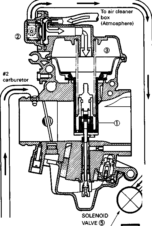
Throttle position sensor Gear position sensor Engine ■ rpm signal V.T.V. (Vacuum Transmitting Valve) @ When negative pressure is applied to the diaphragm chamber of the lift control valve 2, the valve will open. Additionally negative pressure on the cylinder side of #2 carburetor is reduced by means of the V.T.V. 4, and then flows through the vacuum hose to the solenoid valve 5. Current from the ignitor will operate the solenoid valve and change the passage of the vacuum. This vacuum (negative pressure) operates the control valve. STARTER SYSTEM Pulling the starter cable, fuel is drawn into the starter circuit from the float chamber ф. Starter jets (©, (D) meters this fuel, which then flows into fuel pipe @ and mixes with the air coming from the float chamber. The mixture, rich in fuel content, reaches starter plunger © and mixes again with the air coming through a passage extending from behind the diaphragm.
Floats ф and needle valve © are associated with the same mechanism, so that, as the floats ф move up and down, the needle valve © too moves likewise. When fuel level is up in float chamber ©, floats ф are up and needle valve © remains pushed up against valve seat. Under this condition, no fuel enters the float chamber ©. As the fuel level falls, floats ф go down and needle valve © unseats itself to admit fuel into the chamber ©. In this manner, needle valve © admits and shuts off fuel alternately to maintain a practically constant fuel level inside the float chamber ©. REMOVAL • • Remove the fuel tank. (Refer to page 4-3.) • Remove the air cleaner mounting bolts ф.
• Remove the hoses from the air cleaner. • Remove the vacuum chamber mounting bolt ф. • Remove the solenoid valve lead wire coupler. • • Remove the starter cable. DISASSEMBLY Before disassembly, prepare a clean and well lit work place where carburetor components can be laid out nearly and will not get lost. Study the service manual carburetor diagram and familiarize yourself with component locations and the different fuel circuits and their routing through the carburetor. • Disconnectthe air vent hoses®, lift control valve air hoses (D, ®, vacuum hose @ and fuel hose ®. • Remove the solenoid valve ©. A CAUTION_____________________________________ Prior to disassembly, mark with a paint or notch the initial position of the throttle sensor which is PRE-SET accurately at the factory.
• Separate the carburetor assembly. • Disconnect the connecting hoses. [26] • Remove the carburetor top cap ф. A CAUTION
A CAUTION Do not reuse the О-ring to prevent fuel leakage.
• Remove the float assembly ф and needle valve ®. A CAUTION
Do not use a wire for cleaning the valve seat.
• Remove the following parts. © Valve seat @ Pilot jet @ Main jet ® Starter jet © Main jet holder © Pilot screw © Needle jet A CAUTION
Do not use a wire for cleaning of passage and jets. (Refer to PILOT SCREW REMOVAL for E-18 model.)
NOTE: Before removing the pilot screw ©, slowly turn the pilot screw in clockwise and count the number of turns until the screw is lightly seated. Make a note of how many turns were made so the screw can be reset correctly after removing. • Remove the pilot air jet (®. A CAUTION
Do not use a wire for cleaning of jet.
PILOT SCREW REMOVAL (FOR E-18 MODEL) Because harsh cleaning solvents can damage the O-ring seals in the pilot system, the pilot system components should be removed before cleaning. • Use a 1/8" size drill bit with a drill-stop to remove the pilot screw plug. Set the drill-stop 6 mm from the end of the bit to prevent drilling into the pilot screw. Carefully drill through the plug. • Thread a self-tapping sheet metal screw into the plug. Pull on the screw head with pliers to remove the plug. Carefully clean any metal shavings from the area. • Slowly turn the pilot screw in clockwise and count the number of turns until the screw is lightly seated. Make a note of how many turns were made so the screw can be reset correctly after cleaning. • Remove the pilot screw with the spring, washer, and O- ring. • After cleaning reinstall the pilot screw to the original setting by turning the screw in until it lightly seats, and then backing it out the same number of turns counted during disassembly. • CARBURETOR CLEANING
Some carburetor cleaning chemicals, especially dip- type soaking solutions, are very corrosive and must be handled carefully. Always follow the chemical manufacturer's instructions on proper use, handling and strage. AWARNING • Clean all jets with a spray-type carburetor cleaner and blow dry with compressed air. • Clean all circuits of the carburetor thoroughly - not just the perceived problem area. Clean the circuits in the carburetor body with a spray-type cleaner and allow each circuit to soak if necessary to loosen dirt and varnish. Blow the body dry with compressed air. A CAUTION
INSPECTION Check the following items for any damage.
* Pilot jet * Main jet * Main air jet * Pilot air jet * Needle valve * Valve seat * Starter jet * O-rings * Piston valve diaphragm * Lift control valve diaphragm * Jet needle * Needle jet * Main bleed pipe hole * Float * Throttle shaft oil seal * Pilot outlet and by-pass hole
If foreign matter is caught between the valve seat and the needle, the gasoline will continue flowing and cause it to overflow. If the seat and needle are worn beyond the permissible limits, similar trouble will occur. Conversely, if the needle sticks, the gasoline will not flow into the float chamber. Clean the float chamber and float parts with gasoline. If the needle is worn as shown in the illustration, replace it together with a valve seat. Clean the fuel passage of the mixing chamber with compressed air. FLOAT HEIGHT ADJUSTMENT To check the float height, invert the carburetor body, with the float arm kept free, measure the height ® while float arm is just in contact with needle valve by using calipers. Bend the tongue as necessary to bring the height ® to this value. Float height ®: 13.0±1.0 mm (0.51 ±0.04 in) 09900-20102: Vernier calipers SOLENOID VALVE INSPECTION • Connect lead wires from the battery to the terminals in the solenoid valve coupler. • Check the solenoid valve operation by turning the switch to ON and OFF. • If clicks is found, it is in sound condition. V.T.V. INSPECTION
• Blow the VTV from the Orange color side. If air flow out, it is in sound condition. • Also, blow the VTV from opposite side. If air does not flow out, it is in sound condition. If the operation is incorrect, replace the VTV with a new one. THROTTLE POSITION SENSOR INSPECTION Using multi circuit tester, measure the resistance between the terminals as shown in the right illustration. 09900-2500: Multi circuit tester set & Tester knob indication: Resistance! Q) Throttle position sensor resistance: 3.5-6.5 kQ NOTE: When making above test, it is not necessary to remove the throttle position sensor. REASSEMBLY AND REMOUNTING Reassemble and remount the carburetors in the reverse order of disassembly and removal. When engaging carburetors, pay attention to the following points: • Apply a small quantity of grease to the fuel joint pipe O-rings. 99000-25010: SUZUKI SUPER GREASE "A" [30] • Set each throttle valve in such a way that its bottom end ф meets the foremost by-pass This is accomplished by turning the throttle stop screw and throttle valve balance screw.
When removing the throttle position sensor from the carburetor body, install it to the exact position mentioned below; • Measure the resistance © between terminals of the throttle position sensor as shown in the right illustration.
ippii 09900-25008: Multi circuit tester setTester knob indication: Resistance! Q) Throttle position sensor resistance ©: 3.5-6.5 kQ • Measure the resistance © between terminals of the throttle position sensor as shown in the right illustration. • Open the throttle valve fully by turning the throttle lever. • Under above condition, see the throttle position sensor angle to have the resistance © as 76% of the resistance (©• For example: When © is 5 kQ, © should be 3.8 kQ. [31] PISTON VALVE LIFT CONTROL SYSTEM
Air vent hose
Pass through the vacuum hose between throttle cable and starter cable.
Vacuum chamber  Connect the solenoid valve ф and V.T.V. (2) as shown in the following illustration. CARBURETOR CLAMPS
• After all work is completed, mount the carburetors on the engine and the following adjustments are necessary. * Engine idle r/min Page 2- 6 * Throttle cable play Page 2- 7 * Carburetor synchronization .......................... Page 4-22 CARBURETOR SYNCHRONIZATION
NOTE: When synchronize the carburetors, remove the fuel tank and fuel should be supplied by a separate fuel tank CALIBRATING EACH GAUGE • Remove the vacuum hose from No.2 carburetor and fit a proper cap to the vacuum inlet of the No.2 carburetor. • Start up the engine and run it in idling condition for warming up. • Stop the warmed-up engine. • Remove the vacuum inlet cap for No.2 carburetor. • Connect the No.1 rubber hose of balancer gauge to this nipple. 09913-13121: Carburetor balancer [32]
• A hot engine can bum you if you touch the engine. The engine will still be hot for sometime after stopping the engine.   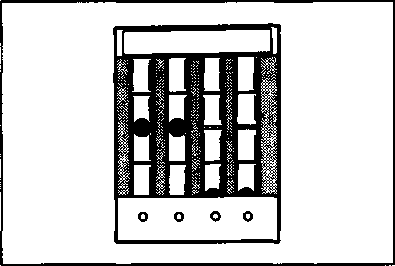  After making sure that the steel ball stays steady at the center line, disconnect the hose from nipple and connect the No.2 hose to the nipple. After making sure that the steel ball stays steady at the center line, disconnect the hose from nipple and connect the No.2 hose to the nipple.
• Turn air screw to bring the other steel ball ф to the center line. • The balancer gauge is now ready for use in balancing the carburetors. CARBURETOR SYNCHRONIZATION To synchronize carburetor throttle valves, remove all the vacuum nipple caps from each carburetor. Connect the balancer gauge Nos. 1 and 2 hoses to vacuum nipples and adjust the balance of two carburetors as follows: • Start up the engine and keep it running at 1 750 r/min to see engine tachometer reading. A correctly adjusted carburetor has the steel balls in the Nos. 1 and 2 tubes at the same level. • If the steel balls are not aligned, adjust the throttle valve balance screw properly to align the balls. A WARNING [33] LUBRICATION SYSTEM AND COOLING SYSTEM OIL PRESSURE Refer to page 2-19. OIL FILTER Refer to page 2-9. OIL SUMP FILTER Refer to page 3-16. NOTE: When separating the crankcase, wash the oil sump filter with cleaning solvent, and then blow compressed air through it to dry off solvent.
ENGINE LUBRICATION/CYLINDER HEAD COOLING SYSTEM CHART 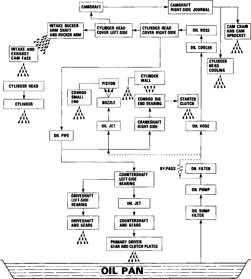
OIL COOLER 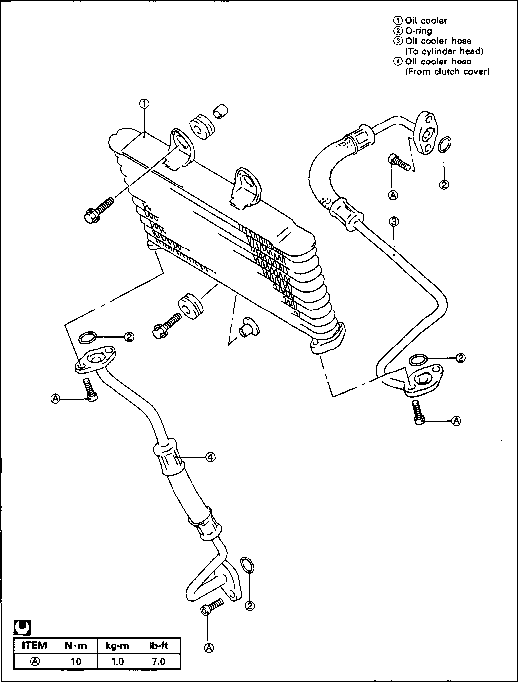
REMOVAL • Drain engine oil. (Refer to page 3-1.) • • Remove the Oil cooler hose mounting bolts. 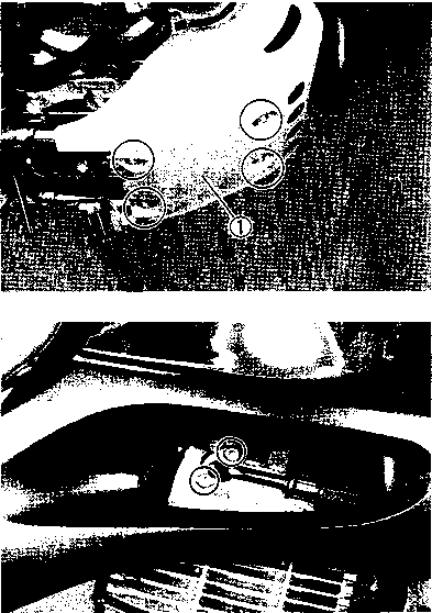 Remove the engine protector ф. Remove the engine protector ф.
• Remove the oil cooler by removing its mounting bolts. 
CHASSIS --------------------------- CONTENTS--------------------------- EXTERIOR PARTS..................................................... 5- 7 REMOVAL.................................................................. 5-2 REMOUNTING.......................................................... 5- 4 FRONT WHEEL......................................................... 5-5 REMOVAL............................................................... 5- 7 INSPECTION AND DISASSEMBLY ................................ 5- 7 REASSEMBLY AND REMOUNTING................................... 5-9 FRONT FORK .......................................................... 5-11 REMOVAL AND DISASSEMBLY ................................... 5-11 INSPECTION............................................................ 5-14 REASSEMBLY AND REMOUNTING................................. 5-15 STEERING............................................................... 5-18 REMOVAL AND DISASSEMBLY ................................... 5-18 INSPECTION............................................................. 5-22 REASSEMBLY AND REMOUNTING................................. 5-23 REAR WHEEL ......................................................... 5-25 REMOVAL............................................................... 5-26 INSPECTION AND DISASSEMBLY................................. 5-28 REASSEMBLY AND REMOUNTING................................. 5-29 REAR SWING ARM AND SUSPENSION.............................. 5-31 REASSEMBLING INFORMATION ................................... 5-32 REMOVAL................................................................ 5-33 INSPECTION AND DISASSEMBLY.................................. 5-35 REASSEMBLY AND REMOUNTING................................. 5-36 FINAL INSPECTION AND ADJUSTMENT........................... 5-37 FRONT BRAKE............................................................ 5-38 BRAKE PAD REPLACEMENT....................................... 5-39 BRAKE FLUID REPLACEMENT...................................... 5-39 CALIPER REMOVAL AND DISASSEMBLY......................... 5-40 CALIPER INSPECTION................................................ 5-41 CALIPER REASSEMBLY AND REMOUNTING .................. 5-41 BRAKE DISC INSPECTION........................................... 5-42 MASTER CYLINDER REMOVAL AND DISASSEMBLY.......... 5-42 MASTER CYLINDER INSPECTION................................. 5-44 MASTER CYLINDER REASSEMBLY AND REMOUNTING..... 5-44 REAR BRAKE.......................................................... 5-45 BRAKE PAD REPLACEMENT........................................ 5-46 BRAKE FLUID REPLACEMENT..................................... 5-46 CALIPER REMOVAL AND DISASSEMBLY .................................... 5-47 CALIPER AND DISC INSPECTION.................................. 5-48 CALIPER REASSEMBLY AND REMOUNTING .................. 5-48 MASTER CYLINDER REMOVAL AND DISASSEMBLY......... 5-49 MASTER CYLINDER INSPECTION.................................. 5-50 MASTER CYLINDER REASSEMBLY AND REMOUNTING..... 5-50 LOWERING THE SEAT HEIGHT..................................... 5-51 OPTIONAL PARTS SUPPLY......................................... 5-51 SPECIAL TOOLS ...................................................... 5-51 FRONT FORK................................................................................................ 5-52 REAR SHOCK ABSORBER........................................... 5-59 SIDE STAND............................................................ 5-61 WARNING LABEL ..................................................... 5-62
EXTERIOR PARTS CONSTRUCTION © Screen © Side fairing (R) ® Side fairing (L) © Center fairing © Side fairing inner cover © Front fairing lower cover (Z) Speedometer panel © Fairing upper bracket ® Fairing brace ® Fuel tank upper cover © Fuel tank cover (R) © Fuel tank cover (L) © Fuel frame cover (R) © Fuel frame cover (L) ® Frame cover (R) ® Frame cover (L) °®OQd. 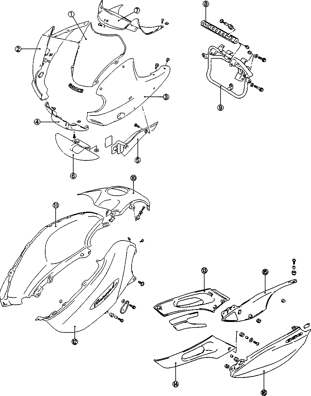
REMOVAL FAIRING • Remove the seat. • Remove the front frame covers (right and left). • Remove the fuel tank covers (right and left). • Remove the four screws ф. • Draw out the four cushions (D and remove the screen.
• Remove the screws ф and ®. • Remove the fairing. 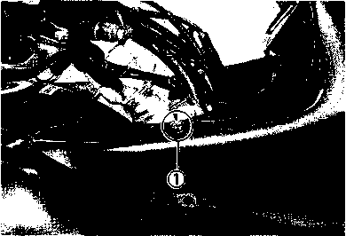 
• Remove the screws (§) and • Remove the instrument panel. •
• Release the lead wires from the fixed clamps. 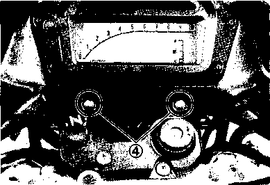 
• Remove the nut ф. • Remove the bolts ®. • Remove the fairing brace with headlight ass'y- FRAME COVER • Remove the seat. • Remove the frame cover mounting screws. • Unhook the hooks and remove the frame cover. REMOUNTING
FRONT WHEEL И ITEM N ■ m kg-m Ib-ft ® 6.5 47.0
2.3 16.5 © 4.5 0.45 3.0 © 2.3 16.5
0 Speedometer sensor 0 Bearing (R) 0 Spacer 0 Bearing (L) 0 Dust seal 0 Spacer © Disc 
Clearance
REMOVAL
• Loosen the front axle holder bolt d) and axle shaft ®. • Carefully position a jack under the chassis tubes and raise until the front wheel is slightly off the ground. • Remove the front wheel by removing the front axle. NOTE: Do not operate the brake lever while dismounting the front wheel. • Remove the disc by removing the mounting bolts. INSPECTION AND DISASSEMBLY WHEEL BEARING Inspect the play of bearing inner ring by hand while mounted in the wheel. Rotate the inner ring by hand to inspect if any abnormal noise occurs or rotating smoothly. Replace the bearing if there is anything unusual. • Remove the dust seal. • 09941-50111: Bearing remover • Insert the adapter into the bearing. • After inserting the wedge bar from the opposite side, lock the wedge bar in the slit of the adapter. • Drive out the bearing by knocking the wedge bar. A CAUTION The removed bearing should be replaced with new ones. [34] [35] REASSEMBLY AND REMOUNTING
WHEEL BEARING • Apply grease to the bearings. 99000-25010: SUZUKI SUPER GREASE "A" • Install the wheel bearings with the special tools.
li'Hi 09924-84510: Bearing installer 09924-84521: Bearing installerA CAUTION First install the left wheel bearing, then install the right wheel bearing. The sealed cover of the bearing must face outside. Refer to page 5-6 for details. [36] • Tighten the front axle ф to the specified torque and then move the front fork up and down. • РЧ Front axle: 65 N-m (6.5 kg-m, 47.0 Ib-ft) Axle holder bolt: 23 N-m (2.3 kg-m, 16.5 Ib-ft) • Reinstall the speed sensor guides ®. NOTE: Clamp the speed sensor wire harness to the white marked part.
• Remove the front fender. • Remove the front fender brace. • Slightly loosen the front fork cap bolt ф after loosening the front fork upper clamp bolt ®to facilitate later disassembly.
• Invert the fork and stroke it several times to drain fork oil. • Hold the fork inverted for a few minutes to drain fork oil. • Remove the damper rod bolt with a 8 mm hexagon wrench and special tools.
• Remove the oil seal stopper ring. 09940-34520: "T" handle 09940-34592: Attachment "G" • Separate the inner tube from the outer tube. A CAUTION_____________________________________ * The removed dust seal and oil seal should be replaced. * • Remove the following parts. ©Oil seal ©Oil seal retainer ©Anti-friction metal (Outer tube) ©Anti-friction metal (Inner tube) INSPECTION FORK SPRING Measure the fork spring free length. If it is shorter than service limit, replace it. Service Limit: 371 mm (14.6 in) INNER TUBE AND OUTER TUBE
m 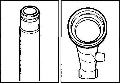 Inspect the inner tube sliding surface for any scuffing and check for bend. Inspect the outer tube sliding surface for any scuffing. Inspect the inner tube sliding surface for any scuffing and check for bend. Inspect the outer tube sliding surface for any scuffing.
REASSEMBLY AND REMOUNTING Reassemble and remount the front fork in the reverse order of removal and disassembly, and also carry out the following steps: INNER TUBE METAL • Install the metal by hand as shown in the illustration. A CAUTION Use special care to prevent damage to the "Teflon" coated surface of the Anti-friction metal when mounting it.
OUTER TUBE METAL, OIL SEAL AND DUST SEAL • Clean the metal groove of outer tube and metal outer surface. • Install the outer tube metal ф, oil seal retainer ® and oil seal ®. 09940-52861: Front fork oil seal installer A CAUTION Use special care to prevent damage to the "Teflon" coated surface of the Anti-friction metal when mounting it. • DAMPER ROD BOLT Apply THREAD LOCK "1342" to the damper rod bolt and tighten it to the specified torque with the special tools and 8-mm hexagon wrench. 99000-32050: THREAD LOCK "1342" 09940-34520: "T" handle 09940-34592: Attachment "G" И Damper rod bolt: 30 N'm (3.0 kg-m, 21.5 Ib-ft) A CAUTION
THREAD LOCK "1342" 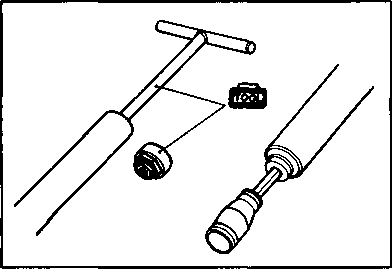 Use a new gasket ф to prevent oil leakage. Use a new gasket ф to prevent oil leakage.
FORK OIL
Fork oil type: Fork oil #15 Fork oil capacity: 655 ml (22.1/23.1 US/Imp oz) вилочное масло Для вилочного масла обязательно используйте переднее вилочное масло, вязкость которого соответствует приведенным ниже характеристикам. Тип масла вилки: Масло вилки #15 Вилка емкость масла: 655 мл (22,1 / 23,1 US/Imp oz) • Hold the front fork vertical and adjust the fork oil level with the special tool. NOTE: When adjusting oil level, remove the fork spring and compress the inner tube fully. 09943-74111: Fork oil level gauge Oil level: 143 mm (5.6 in) При регулировке уровня масла, снять вилку пружину и сжать полностью внутреннюю трубку. 09943-74111: Датчик уровня масла вилки Уровень масла: 143 мм (5.6 в) FORK SPRING • Install the fork spring (D, washer spacers (D, @ and front fork cap bolt (§)■ - .............. 1^?'' -Щ ; © © , ® ® ©
• Align the top surface ф of the inner tube to the top surface © of the steering stem upper bracket. • Tighten each bolt to the specified torque. Щ Front fork cap bolt d): 23 N-m (2.3 kg-m, 16.5 Ib-ft) Upper clamp bolt @: 29 N ■ m (2.9 kg-m, 21.0 Ib-ft) Lower clamp bolt d): 23 N-m (2.3 kg-m, 16.5 Ib-ft)
STEERING ITEM N ■ m kg-m Ib-ft ® 2.3 16.5
9.0 65.0 © 2.5 18.0
2.9 21.0 © 2.3 16.5
© Handlebar clamp © Handlebar holder © Cap © Damper (Upper) © Steering stem upper bracket © Damper (Lower) © Steering stem nut © Bearing (Upper) © Bearing (Lower) ® Steering stem lower bracket 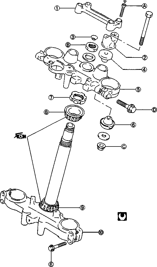
REMOVAL AND DISASSEMBLY • Remove the firing. (Refer to page 5-2.) • Remove the fuel tank. (Refer to page 4-3.) • Remove the front wheel. (Refer to page 5-5.) • Remove the front fork. (Refer to page 5-11.) •
• Remove the brake hose clamp bolt and speed sensor clamp screw. • Remove the speedometer coupler and release the lead wire from the fixed clamp. • Remove the throttle grip case screws. • Disconnect the throttle cables. [40] • Disconnect the right handlebar switch lead wire couplers and ignition switch lead wire coupler. • Loosen the clamp bolt ф. • Draw out the throttle cable and right handlebar switch lead wire from the clamps. Remove the brake switch lead wire. Remove the front brake master cylinder with brake hose. • Remove the caps. • Remove the handlebars by removing the four mounting bolts. • Remove the handlebar holder by removing the mounting nuts. • Remove the steering stem upper bracket by removing the stem head nut. • Loosen the steering stem nut with the special tools. цщ 09940-14911: Steering stem nut socket wrench 09940-14960: Steering stem nut socket • Remove the steering stem lower bracket. NOTE: Hofd the steering stem lower bracket by hand to prevent it from falling. li[41]W< • Remove the upper bearing. • Remove the steering stem lower bearing with a chisel. A CAUTION The removed bearing should be replaced with a new one. • Remove the steering stem bearing races, upper and lower with the special tools. 09941-54911: Steering race remover 09941-74910: Steering bearing remover and installer INSPECTION * Inspect the removed parts for the following abnormalities. * Handlebars distortion * Handlebar clamp wear * Race wear and brinelling * Abnormal noise of bearing * Distortion of steering stem
ISKI 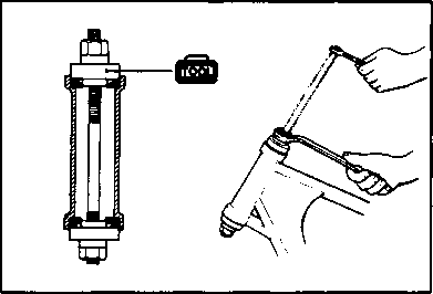   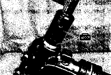  REASSEMBLY AND REMOUNTING REASSEMBLY AND REMOUNTING
Reassemble and remount the steering stem in the reverse order of removal and disassembly. Pay attention to the following points: BEARING RACES • Press in the upper and lower bearing races with the special tool. 09941-34513: Steering outer race installer BEARING • Press in the lower bearing with the special tool. 09925-18010: Steering bearing installer • Apply grease to the upper and lower bearings. jfZjH 99000-25010: SUZUKI SUPER GREASE "A" STEM NUT • Tighten the steering stem nut to 45 N-m (4.5 kg-m, 32.5 Ib-ft) with the special tools. 09940-14911: Steering stem nut wrench 09940-14960: Steering stem nut socket • NOTE: Before tightening the steering stem nut, install the front fork temporarily. • Tighten the handlebar holder nuts to the specified torque. QQ Handlebar holder nut: 25 N-m (2.5 kg-m, 18.0 Ib-ft) NOTE: Before tighten the handlebar holder nuts, install the handlebars temporarily. HANDLEBARS • Set the handlebars to match its punched mark to the mating face of the holder. • Secure the each handlebar clamp in such a way that the clearances @ ahead and behind of the handlebars are equalized. QQ Handlebar clamp bolt: 23 N-m (2.3 kg-m, 16.5 Ib-ft) • Turn the handlebars all the way left and make sure that clearance between the strap ® of the left handlebar switch and fuel tank cover ® is 5 mm (0.2 in). If it is under 5 mm (0.2 in), adjust the handlebar position so that the clearance has specified one. A CAUTION_____________________________________________
REAR WHEEL 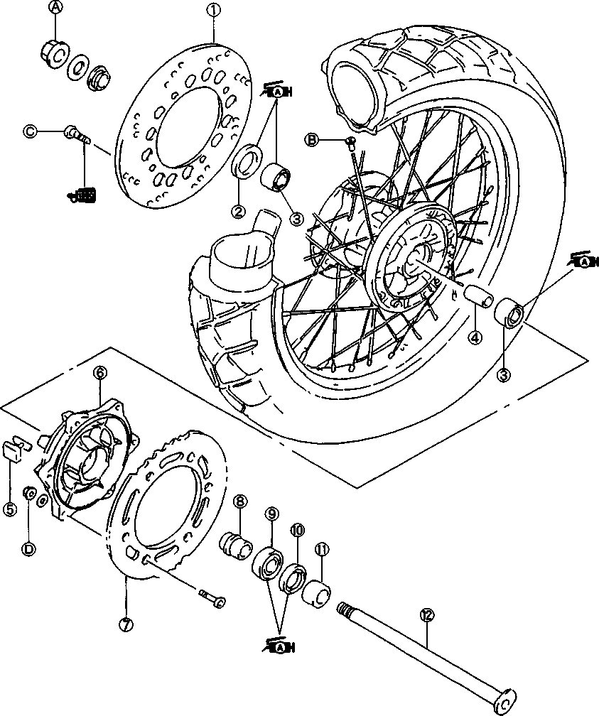
H ITEM Nm kg-m Ib-ft ® 11.0 79.5
4.5 0.45 3.0 © 2.3 16.5
2.7 19.5 ® Disc © Dust seal ® Bearing ® Spacer © Damper © Sprocket drum © Rear sprocket © Spacer © Bearing © Dust seal © Spacer © Rear axle
REMOVAL • Remove the rear lower fender by removing bolts and screws. • Loosen the axle nut. • Support the motorcycle with a jack. • Remove the axle nut and axle. • Remove the rear wheel by disengaging the drive chain. A CAUTION_____________________________________________
• Remove the spacer ф. • Remove the rear sprocket by removing the mounting nuts and bolts. • Remove the dust seal with the special tool. 09913-50121: Dust seal remover [42]
K-FH №511 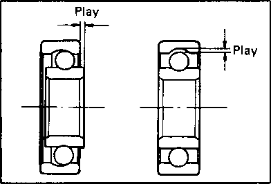    INSPECTION AND DISASSEMBLY INSPECTION AND DISASSEMBLY
TIRE........................................................ Refer to page 2-13. REAR WHEEL........................................ Refer to page 5- 7. WHEEL BEARING AND SPROCKET DRUM BEARING Inspect the play of bearing inner ring by hand while mounted in the wheel or sprocket drum. Rotate the inner ring by hand to inspect any abnormal noise occurs or rotating smoothly. Replace the bearing if there is anything unusual. Remove the both bearing with the special tool in the following procedures. • Insert the adapter into the bearing. 09941-50111: Bearing remover • After inserting the wedge bar from the opposite side, lock the wedge bar in the slit of the adapter. • Drive out the bearing by hammering the wedge bar. A CAUTION The removed bearings should be replaced with new ones. • Remove the sprocket drum bearing with the special tool. 09913-75830: Bearing remover A CAUTION REAR AXLE • Using a dial gauge, check the rear axle for runout. • If the runout exceeds the limit, replace the rear axle. 09900-20606: Dial gauge (1/100 mm) 09900-20701: Magnetic stand 09900-21304: "V" block set Service Limit: 0.25 mm (0.010 in) REAR SPROCKET Inspect the sprocket teeth for wear. If they are worn as illustrated, replace the sprocket and drive chain. REAR SPROCKET DAMPER Inspect the dampers for wear and damage. If any defects are found, replace the dampers as a set. REASSEMBLY AND REMOUNTING Reassemble and remount the rear wheel in the reverse order of removal and disassembly. Pay attention to the following points: WHEEL BEARING • Apply grease to the bearings. 99000-25010: SUZUKI SUPER GREASE "A" • Install the wheel bearings with the special tools. 09924-84510: Bearing installer 09924-84521: Bearing installer A CAUTION First install the right wheel bearing, then install the left wheel bearing.
Refer to page 5-26 for details.
ЕРИ» • Install the rear sprocket drum bearing by using a bearing installer.09913-75810: Bearing installer NOTE: Seal side of bearing goes toward outside. BRAKE DISC • Apply THREAD LOCK SUPER "1360" to the disc bolts and tighten them to the specified torque. NOTE: Make sure that the brake disc is clean and free of any greasy matter. 99000-32130: THREAD LOCK SUPER "1360" [5 Disc bolt: 23 N-m (2.3 kg-m, 16.5 Ib-ft) SPROCKET • Tighten the sprocket nuts to the specified torque. £5 Sprocket nut: 27 N-m (2.7 kg-m, 19.5 Ib-ft) NOTE: Face the stamped mark on the sprocket to outside. REAR AXLE NUT • Adjust the chain slack after rear wheel installation. (Refer to page 2-9.) • Tighten the axle nut to the specified torque.
REAR SWINGARM AND SUSPENSION
REASSEMBLING INFORMATION
REMOVAL • • Remove the rear wheel. (Refer to page 5-27.) • Disconnect the brake hose from the hose guides. • Remove the cushion lever center nut ф and bolt. • Remove the rear shock absorber lower mounting bolt ®. • Remove the cushion lever by removing the mounting nut (D and bolt. • Take off the air cleaner drain hose from clamp. [43] • Remove the rear shock absorber reservoir tank ф by loosening its clamp screws d). • • Remove the rear shock absorber by removing the mounting bolt Remove the cushion rods.
• Remove the drive chain buffer. • Remove the brake hose guides and mud guard.
Il'M*
INSPECTION AND DISASSEMBLY SWINGARM Inspect the swingarm for wear or damage. Inspect the spacer for any flaws or other damage. Insert the spacer into the bearing and check the play to move the spacer up and down. If an excessive play is noted, replace the bearing with a new one. • Draw out the swingarm bearings and spacer with the special tools. ЕРИ» 09923-74510: Bearing remover 09930-30102: Sliding shaft A CAUTION The removed bearings should be replaced with new ones. CUSHION LEVER Inspect the spacer for any flaws or other damage. Insert the spacer into the bearing and check the play to move the spacer up and down. If an excessive play is noted, replace the bearing with new ones. • Draw out the bearing with the special tools and appropriate tool. 09923-73210: Bearing remover 09930-30102: Sliding shaft A CAUTION The removed bearing should be replaced with new ones.    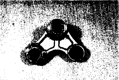  • Remove the cushion lever dust seals and spacers. SHOCK ABSORBER Inspect the shock absorber for oil leakage or other damage. If any defects are found, replace the shock absorber with new a one. SWINGARM PIVOT SHAFT Using a dial gauge, check the pivot shaft runout and replace it if the runout exceeds the limit. 09900-20606: Dial gauge 09900-20701: Magnetic stand 09900-21304: V-block Service Limit: 0.3 mm (0.01 in) REASSEMBLY AND REMOUNTING Reassemble and remount the rear swingarm and suspension in the reverse order of removal and disassembly. Pay attention to the following points: SWINGARM BEARING • Install the new bearing with the special tool. 09941-34513: Bearing installer NOTE: When installing the bearing, punch-marked side of bearing faces outside. CUSHION LEVER BEARING • Install the new bearing with the special tool. 09924-84521: Bearing installer NOTE: When installing the bearing, punch-mark side of bearing faces outside. • Remount the rear suspension. (Refer to page 5-33.) FINAL INSPECTION AND ADJUSTMENT After installing the rear suspension and wheel, the following adjustments are required before driving. * Drive chain Page 2-10. * Rear brake pedal height..................................... Page 2-12. * Tire pressure Page 2-14. SHOCK ABSORBER SPRING PRE-LOAD ADJUSTMENT Spring pre-load is adjustable by changing the spring adjuster ring position after removing the shock absorber. Turning the spring adjuster ring counterclockwise or clockwise as viewed from for increase or decrease the spring pre-load after loosening the adjuster lock ring. The standard set length is 169.2 mm (6.7 in).
09910-60611: Universal clamp wrench
After adjusting the pre-load, tighten the spring adjuster lock ring securely. ——..................... Spring pre-set length Softest 180.0 mm (7.0 in) Standard 169.2 mm (6.7 in) Stiffest 160.0 mm (6.3 in)
SHOCK ABSORBER DAMPING FORCE ADJUSTMENT Fully turn the damping force adjuster clockwise. It is at stif- fest position and turn it out to the standard setting position. STD position: 13 clicks turns out
FRONT BRAKE * This brake system is filled with a ethylene glycol-based DOT 4 brake fluid. Do not use or mix different types of fluid such as silicone-based or petroleum-based. * Do not use any brake fluid taken from old, used or unsealed containers. Never reuse brake fluid left over from the last servicing or stored for long periods. * When storing the brake fluid, seal the container completely and keep away from children. * When replenishing brake fluid, take care not to get dust into fluid. * When washing brake components, use fresh brake fluid. Never use cleaning solvent. * A contaminated brake disc or brake pad reduces braking performance. Discard contaminated pads and clean the disc with high quality brake cleaner or neutral detergent. A CAUTION Handle brake fluid with care: the fluid reacts chemically with paint, plastics rubber materials etc.
AWARNING
BRAKE PAD REPLACEMENT • Remove the caliper by removing the mounting bolts ф. A CAUTION * Do not operate the brake lever while dismounting the pads. * Replace the brake pad as a set, otherwise braking performance will be adversely affected. • Remove the cotter pin ® and remove the mounting pin <D. • Remove the brake pads and replace with new ones. • Install the mounting pin and cotter pin. • Tighten the mounting bolts to the specified torque. И Front brake caliper mounting bolt: 39 N-m (3.9 kg-m, 28.0 Ib-ft) NOTE: After replacing the brake pads, pump with the brake lever few times to operate the brake correctly and then check the brake fluid level. BRAKE FLUID REPLACEMENT • Place the motorcycle on a level surface and keep the handlebars straight. • Remove the master cylinder reservoir cap and diaphragm. • Suck up the old brake fluid as much as possible. • Fill the reservoir with fresh brake fluid. ^ Specification and Classification: DOT 4 • Connect a clear hose ® to the air bleeder valve (D, and insert the free end of hose into a receptacle. • Loosen the bleeder valve and pump the brake lever until no more old brake fluid flows out of the bleeder valve. • Close the air bleeder valve, and disconnect a clear hose. Fill the reservoir with fresh brake fluid to the upper end of the inspection window. A CAUTION
CALIPER REMOVAL AND DISASSEMBLY • • Remove the brake caliper by removing the caliper mounting bolts A CAUTION____________________________________________ Never reuse the brake fluid left over from previous servicing and stored for long periods.
Brake fluid, if it leaks, will interfere with safe running and discolor painted surfaces. Check the brake hose and hose joints for cracks and oil leakage. AWARNING • Remove the pads. (Refer to page 5-39.) • Remove the caliper holder ®. • • Place a rag over the pistons to prevent it from popping out and then force out the piston with compressed air.
Do not use high pressure air to prevent piston damage.
A CAUTION__________________________________________ Do not reuse the dust seals and piston seals to prevent fluid leakage. О О О о CALIPER INSPECTION
Inspect the caliper cylinder wall for nicks, scratches or other damage. PISTON Inspect the piston surface for any scratches or other damage. CALIPER REASSEMBLY AND REMOUNTING Reassemble the caliper in the reverse order of removal and disassembly. Pay attention to the following points: • Wash the caliper bores and pistons with specified brake fluid. Particularly wash the dust seal grooves and piston seal grooves. ^ Specification and Classification: DOT 4 A CAUTION * Wash the caliper components with fresh brake fluid before reassembly. * Do not wipe the brake fluid off after washing the components. * When washing the components, use the specified brake fluid. Never use different types of fluid or cleaning solvent such as gasoline, kerosine or the others. * Replace the piston seals and dust seals with new ones when reassembly. Apply the brake fluid to both seals when installing them. • Apply SUZUKI SILICONE GREASE to the caliper axles. 99000-25100: SUZUKI SILICONE GREASE • Tighten each bolt to the specified torque. ГЧ Caliper mounting bolt ф: 39 N ■ m (3.9 kg-m, 28.0 Ib-ft) Brake hose union bolt (D: 23 N-m (2.3 kg-m, 16.5 Ib-ft) NOTE: Before remounting the caliper, push the piston all the way into the caliper. A CAUTION Bleed air from the system after reassembling the caliper. (Refer to page 2-12.)
BRAKE DISC INSPECTION • Remove the front and rear wheels. (Refer to pages 5-7 and 5-27.) SFHl Service Limit Front disc: 4.0 mm (0.16 in) Rear disc: 4.0 mm (0.16 in) SPOT Service Limit Front and Rear disc: 0.3 mm (0.012 in) • Remove the disc. (Refer to pages 5-7 and 5-27.) • Install the disc. (Refer to pages 5-9 and 5-30.) • Remove the brake lever. • Disconnect the front brake switch lead wires. MASTER CYLINDER REMOVAL AND DISASSEMBLY • Loosen the brake master cylinder mounting bolts and remove the rear view mirror. 09900-20606: Dial gauge (1/100 mm) 09900-20701: Magnetic stand Measure the runout with a dial gauge. Replace the disc if the runout exceeds the service limit. 09900-20205: Micrometer (0-25 mm) Visually check the brake disc for damage or cracks. Measure the thickness with a micrometer. Replace the disc if the thickness is less than the service limit or if damage is found. 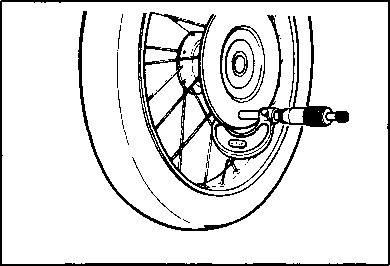 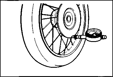 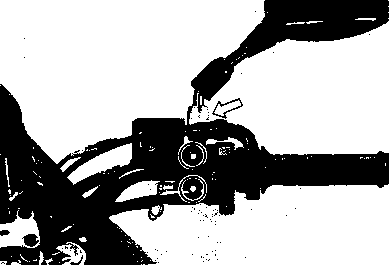 
and 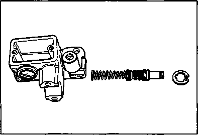 • Place a rag underneath the union bolt on the master cylinder to catch any spilled drops of brake fluid. Remove the union bolt and disconnect the brake hose/master cylinder joint. • Place a rag underneath the union bolt on the master cylinder to catch any spilled drops of brake fluid. Remove the union bolt and disconnect the brake hose/master cylinder joint.
A CAUTION Immediately and completely wipe off any brake fluid contacting any part of the motorcycle. The fluid reacts chemically with paint, plastics and rubber materials, etc. and will damage them severely.
• Remove the front brake switch.  • Remove the master cylinder assembly. • Remove the reservoir cap and diaphragm. • Drain brake fluid. [44] MASTER CYLINDER INSPECTION Inspect the master cylinder bore for any scratches or other damage. Inspect the piston surface for any scratches or other damage.
MASTER CYLINDER REASSEMBLY AND REMOUNTING • Reassemble the master cylinder in the reverse order of removal and disassembly. Pay attention to the following points: A CAUTION * Wash the master cylinder components with fresh brake fluid before reassembly. Never use cleaning solvent or gasoline to wash them. * Do not wipe the components with a rag. * Apply brake fluid to the cylinder bore and all the component to be inserted into the bore. ^ Specification and Classification: DOT 4 • When remounting the master cylinder on the handlebars, align the master cylinder holder's lower mating surface ф with punched mark @ on the handlebars and tighten the upper clamp bolt first as shown. H Master cylinder mounting bolt: 10 N-m (1.0 kg-m, 7.0 Ib-ft) NOTE: Install and adjust the rear view mirror before tightening the master cylinder mounting bolts. A CAUTION
Master cylinder
REAR BRAKE © Piston © Pad © Shim © Caliper body © Caliper holder ii WARNING A CAUTION_____________________________________________________________________ Handle brake fluid with care: the fluid reacts chemically with paint, plastics, rubber materials etc. * This brake system is filled with a ethylene glycol-based DOT 4 brake fluid. Do not use or mix different types of fluid such as silicone-based or petroleum-based. * Do not use any brake fluid taken from old, used or unsealed containers. Never reuse brake fluid left over from the last servicing or stored for long periods. * When storing the brake fluid, seal the container completely and keep away from children. * When replenishing brake fluid, take care not to get dust into fluid. * When washing brake components, use fresh brake fluid. Never use cleaning solvent. * A contaminated brake disc or brake pad reduces braking performance. Discard contaminated pads and clean the disc with high quality brake cleaner or neutral detergent. © Reservoir tank © Reservoir tank hose © Brake hose © Piston/cup set ITEM N • m kg-m Ib-ft ® 1.8 13.0
2.5 0.25 1.8 © 2.3 16.5 © 0.8 6.0 © 2.3 16.5 © 1.0 7.0 © 2.3 16.5 © 1.8 13.0
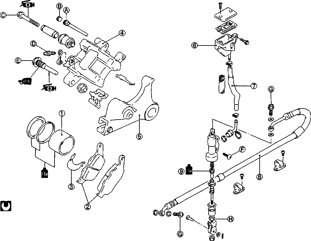
• Remove the rear lower fender ф. Remove the screws @. Remove the brake pad mounting pin Remove the mounting bolt @ • Slide the caliper housing to outside then remove the pads (D. A CAUTION * Do not operate the brake pedal while dismounting the pads. * Replace the brake pad as a set, otherwise braking performance will be adversely affected. • Install the new pads correctly. • Tighten the caliper mounting bolt and pad mounting pin to the specified torque. Ш Brake caliper mounting bolt: 23 IM-m (2.3 kg-m, 16.5 lb-ft) Pad mounting pin: 18 IM-m (1.8 kg-m, 13.0 lb-ft) NOTE: After replacing the brake pads, pump with brake pedal few times to operate the brake correctly and then check the brake fluid level. BRAKE FLUID REPLACEMENT • Remove the reservoir tank mounting bolt. • Replace brake fluid in the same manner of the front brake. (Refer to page 5-40.) ^jj Specification and Classification: DOT 4 1 A CAUTION
CALIPER REMOVAL AND DISASSEMBLY • Place a rag underneath the union bolt on the brake caliper to catch any spilled drops of brake fluid. • Remove the union bolt and catch brake fluid in a suitable receptacle. A CAUTION Never reuse the brake fluid left over from previous servicing and stored for long periods.
Brake fluid, if it leaks, will interfere with safe running and discolor painted surfaces. Check the brake hose and hose joints for cracks and fluid leakage. AWARNING • Remove the caliper by removing the mounting bolts. • Remove the pads. (Refer to page 5-46.) • Place a rag over the piston to prevent popping up. Force out the piston with an air gun. A CAUTION .*£0
* ,, }№  r Do not use high pressure air to prevent piston damage. • Remove the dust seal and piston seal. A CAUTION___________________________________________
CALIPER AND DISC INSPECTION
CALIPER REASSEMBLY AND REMOUNTING Reassemble and remount the caliper in the reverse order of removal and disassembly. Pay attention to the following points: A CAUTION * Wash the caliper components with fresh brake fluid before reassembly. Never use cleaning solvent or gasoline to wash them. * Apply brake fluid to the caliper bore and piston to be inserted into the bore. ^ Specification and Classification: DOT 4 • install the brake pads and remount the brake caliper. (Refer to page 5-47.) • Tighten the brake hose union bolt to the specified torque. И Brake hose union bolt: 23 N-m (2.3 kg-m, 16.5 Ib-ft) A CAUTION
• Place a cloth underneath the union bolt on the master cylinder to catch spilled drops of brake fluid. • Remove the union bolt ф. • Loosen the rear brake rod lock nut @. • Remove the master cylinder mounting bolts ®. • Disconnect the brake rod by rotating brake rod • Disconnect the brake hose ©. • Remove the connector by removing the circlip 09900-06108: Snap ring pliers • Remove the О-ring A CAUTION The removed О-ring should be replaced with a new one. [45] [46] MASTER CYLINDER REASSEMBLY AND REMOUNTING Reassemble and remount the master cylinder in the reverse order of removal and disassembly. Pay attention to the following points: A CAUTION * Wash the master cylinder components with fresh brake fluid before reassembly. Never use cleaning solvent or gasoline to wash them. * Apply brake fluid to the cylinder bore and all the internal to be inserted into the bore. Specification and Classification: DOT 4 MASTER CYLINDER • Tighten the bolts and nut to the specified torque. Ш Master cylinder mounting bolt ф: 10 N-m (1.0 kg-m, 7.0 Ib-ft) Master cylinder rod lock nut ®: 18 N-m (1.8 kg-m, 13.0 Ib-ft)
LOWERING THE SEAT HEIGHT The seat height can be lowered 30 mm by changing the location of the inner parts of the front fork and rear shock absorber and replacing the side-stand with optional one. OPTIONAL PARTS SUPPLY Part No. Part Name PCS 42300-04820 Non Side-stand (Silver painting) 09248-10006 Plug 62184-32E00 Plate 68380-04F00 Label set AWARNING
When installing the optional center-stand, install the shorter, silver-colored one. If the optional center-stand has been installed to the motorcycle, replace the center-stand with shorter, silver-colored one. SPECIAL TOOLS This special tool is used for loosening and tightening the front fork damper rod bolt. 09940-34520: "T" handle This special tool is used with tool (09940-34520) for loosening and tightening the front fork damper rod bolt. 09940-34592: Attachment "G" This special tool is used for adjusting the front fork oil level. 09943-74111: Front fork oil level gauge \ This special tool is used for loosening and tightening the rear shock absorber ring. 09910-60611: Universal clamp wrench
FRONT FORK 
• Remove the front brake caliper mounting bolts ф. • Remove the speed sensor guides d). • Loosen the front axle holder bolts d) and axle • Carefully position a jack under the chassis tubes and raise until the front wheel is slightly off the ground. • Remove the front wheel by removing the axle. I A CAUTION Do not operate the brake lever while dismounting the front wheel. • Remove the front brake hose clamp bolt [48]
• Slightly loosen the front fork cap bolt ф after loosening the front fork upper clamp bolt @ to facilitate later disassembly. • Remove the front fork by loosening the lower clamp bolts ®. • Remove the other side front fork the same way.
i'K51  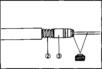  • Remove the damper rod bolt with a 8 mm hexagon wrench and special tools. • Remove the damper rod bolt with a 8 mm hexagon wrench and special tools.
09940-34520: "T" handle 09940-34592: Attachment "G"
(D © • Remove the damper rod ф with spring d).
lKi]> REASSEMBLY AND REMOUNTINGReassemble and remount the front fork and front wheel in the reverse order of removal and disassembly. Pay attention to the following points: • Install the removed spacer ® and spring ® to the damper rod as shown in the photo. • Insert the damper rod assembly to the inner tube with the special tool. 09940-34520: "T" handle 09940-34592: Attachment "G" • Apply THREAD LOCK "1342" to the damper rod bolt. ШШ 99000-32050: THREAD LOCK "1342" A CAUTION
IK»!'    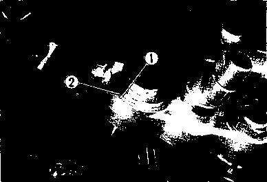  • Tighten the damper rod bolt to the specified torque with a 8 mm hexagon wrench and special tools. • Tighten the damper rod bolt to the specified torque with a 8 mm hexagon wrench and special tools.
£5 Damper rod bolt: 30 N-m (3.0 kg-m, 21.5 Ib-ft) 09940-34520: "T" handle 09940-34592: Attachment "G" • Pour specified fork oil into the inner tube. Fork oil type: Fork oil #15 99000-99044-15G: SUZUKI FORK OIL #15 Capacity (each leg): 699 ml (23.6/24.6 US/Imp oz) • Hold the front fork vertical and adjust the fork oil level with the special tool. 09943-74111: Fork oil level gauge Oil level: 92 mm (3.6 in) NOTE: When adjusting the oil level, remove the fork spring and compress the inner tube fully. • Install the fork spring. • Install the washer and fork cap bolt, and tighten the cap bolt your hand. • When remounting the front fork, align the upper surface ф of the inner tube with the upper surface ф of the steering stem upper bracket. [49] • Install the brake hose clamp ф.
• Reassemble the front fender brace and front fender.  • Align the drive lugs ф with the recesses (2) of the wheel hub. [50] • Tighten the front axle ф to the specified torque and then move the front fork up and down. • Tighten the axle pinch bolt (g) to the specified torque. Щ Front axle: 65 N-m (6.5 kg-m, 47.0 Ib-ft) Axle pinch bolt: 23 N-m (2.3 kg-m, 16.5 Ib-ft) • Reinstall the speed sensor guides ®. NOTE:
© Rear shock absorber ® Plate (Optional part) ® Plug (Optional part) ® Spring seat  ta>  REAR SHOCK ABSORBER Standard spring seat ® and mounting Changed spring seat ® and mounting position position. REMOVAL AND DISASSEMBLY
• Remove the rear shock absorber reservoir tank ф by loosening its clamp screws • Take off the hose from the clamps ф>. • Remove the rear shock absorber by removing the mounting bolts @. • Loosen the spring pre-load adjuster lock ring and adjuster ring fully with the special tool. 09910-60611: Universal clamp wrench • Remove the spring seat ф and plate ® by moving the cushion (D to the shock absorber cylinder side. NOTE: The removed plate ® will not be used when reassembling the shock absorber. REASSEMBLY AND REMOUNTING Reassemble and remount the rear shock absorber and air cleaner in the reverse order of removal and disassembly. Pay attention to the following points: • When installing the spring seat ф to the shock absorber, invert it from standard position. • Position the cushion ® against washer ®. • ®(D 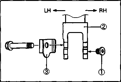 Tighten the spring adjuster ring and adjust the spring pre-load with the special tool. The standard set length is 169.2 mm (6.7 in). Tighten the spring adjuster ring and adjust the spring pre-load with the special tool. The standard set length is 169.2 mm (6.7 in).
• After adjusting the pre-load, tighten the adjuster lock ring securely. 09910-60611: Universal clamp wrench SPRING SETTING TABLE —— Spring pre-set length Softest 180.0 mm (7.0 in) Standard 169.2 mm (6.7 in) Stiffest 160.0 mm (6.3 in)
• Tighten the plug ф (optional part) to the lower mounting part of shock absorber <2> to the specified torque. H Plug: 30 N m (3.0 kg-m, 21.5 Ib-ft) • Install the shock absorber lower plate @ (optional part) as shown in the illustration. • Install the rear shock absorber and tighten it to the specified torque. Mounting bolt: 45 N-m (4.5 kg-m, 32.5 Ib-ft) (Upper and lower) SIDE-STAND
A new, shorter, silver-colored optional side-stand must be installed for safe parking. SIDE-STAND REMOVAL AND INSTALLATION • Support the motorcycle with jack or wooden block. • Remove the original side-stand by removing mounting nut and bolt. • Apply SUZUKI SUPER GREASE "A" to the side-stand pivot portion and spring hooks. 99000-25010: SUZUKI SUPER GREASE "A" • Install the optional shorter side-stand {silver-colored) and springs correctly as shown in the illustration. • Tighten the side-stand mounting bolt and nut to the specified torque. И Bolt: 50 N-m (5.0 kg-m, 36.0 Ib-ft) Nut: 55 N-m (5.5 kg-m, 40.0 Ib-ft) AWARNING NOTE: Make sure that the side-stand switch operation after installing the side-stand. WARNING LABEL • Attach the warning label (optional part) to the swingarm as shown in the illustration. NOTE:
Tire pres Warn sure label ng label
Swingarm Label No. left side Select the appropriate language label for your country. ELECTRICAL SYSTEM CONTENTS CAUTIONS IN SERVICING................................ 6- 1 LOCATION OF ELECTRICAL COMPONENTS .............. 6-3 CHARGING SYSTEM ....................................... 6- 5 DESCRIPTION........................................... 6- 5 TROUBLESHOOTING..................................... 6- 6 INSPECTION............................................. 6- 7 STARTER SYSTEM AND SIDE-STAND/IGNITION INTERLOCK SYSTEM................................................... 6-10 STARTER SYSTEM DESCRIPTION ....................... 6-10 SIDE-STAND/IGNITION INTERLOCK SYSTEM DESCRIPTION.... 6-10 TROUBLESHOOTING..................................... 6-12 STARTER MOTOR REMOVAL AND DISASSEMBLY......... 6-13
STARTER MOTOR REASSEMBLY......................... 6-14 STARTER RELAY INSPECTION............................ 6-15 SIDE-STAND/IGNITION INTERLOCK SYSTEM INSPECTION. 6-16 IGNITION SYSTEM........................................ 6-19 DESCRIPTION........................................... 6-19 TROUBLESHOOTING..................................... 6-20 INSPECTION............................................. 6-21 COMBINATION METER .................................. 6-25 REMOVAL............................................... 6-25 DISASSEMBLY.......................................... 6-25 INSPECTION............................................. 6-26 FUEL METER............................................ 6-28 FUEL METER INSPECTION............................... 6-28 FUEL LEVEL GAUGE REMOVAL/INSTALLATION........... 6-28 FUEL LEVEL GAUGE INSPECTION........................ 6-29 LAMPS.................................................. 6-30 HEADLIGHT............................................. 6-30 TAIL/BRAKE LIGHT, TURN SIGNAL LIGHT AND LICENSE PLATE LIGHT................................... 6-31 TURN SIGNAL RELAY ................................... 6-32 SWITCHES.............................................. 6-33 BATTERY............................................... 6-34 SPECIFICATIONS........................................ 6-34 INITIAL CHARGING....................................... 6-34 SERVICING.............................................. 6-35 RECHARGING OPERATION............................... 6-36 CAUTIONS IN SERVICING CONNECTOR • When connecting a connector, be sure to push it in until a click is felt. • Inspect the connector for corrosion, contamination and breakage in its cover. COUPLER • With a lock type coupler, be sure to release the lock before disconnecting it and push it in fully till the lock works when connecting it. • When disconnecting the coupler, be sure to hold the coupler itself and do not pull the lead wires. • Inspect each terminal on the coupler for being loose or bent. • Inspect each terminal for corrosion and contamination. CLAMP • Clamp the wire harness at such positions as indicated in "WIRE HARNESS ROUTING" (Refer to pages 7-10,11,12 and 13.). • Bend the clamp properly so that the wire harness is clamped securely. • In clamping the wire harness, use care not to allow it to hang down. • Do not use wire or any other substitute for the band type clamp. FUSE • When a fuse blows, always investigate the cause, correct it and then replace the fuse. • Do not use a fuse of a different capacity. • Do not use wire or any other substitute for the fuse. SEMI CONDUCTOR EQUIPPED PART • Be careful not to drop the part with a semi-conductor built in such as a CDI unit and regulator/rectifier. • BATTERY • The MF battery used in this vehicle does not require maintenance as inspection of electrolyte level and replenishment of water. • No hydrogen gas is produced during normal charging of the battery, but such gas may be produced when it is overcharged. Therefore, do not bring fire near the battery while it is being charged. • Note that the charging system for the MF battery is different from that of an ordinary battery. Do not replace with an ordinary battery. CONNECTING BATTERY • When disconnecting terminals from the battery for disassembly or servicing, be sure to disconnect the negative (©) terminal first. • When connecting terminals to the battery, be sure to connect the positive (®) terminal first. • If the terminal is found corroded, remove the battery, pour warm water over it and clean with a wire brush. • Upon completion of connection, apply grease lightly. • Put a cover over the positive (©) terminal. WIRING PROCEDURE • Route the wire harness properly according to "WIRE HARNESS ROUTING" (Refer to pages 7-10,11,12 and 13.). USING MULTI CIRCUIT TESTER • Be sure to use positive (©) and negative (©) probes of the tester properly. Their false use may cause damage in the tester. • If the current values are not known, start measuring in the higher range. • Taking a measurement where voltage is applied in the resistance range may cause damage in the tester. When measuring resistance, check to make sure that no voltage is applied there. • After using the tester, turn the switch to the OFF position. A CAUTION____________________________________
LOCATION OF ELECTRICAL COMPONENTS ©Battery ©Fuses ©Turn signal relay ©CDI unit ©Starter relay ©Main fuse ©Generator ©Starter motor ©Side-stand switch 
©Regulator/rectifier ©Side-stand interlock relay CHARGING SYSTEM DESCRIPTION The circuit of the charging system is indicated in the figure, which is composed of an AC generator, regulator/rectifier unit and battery. The AC current generated from AC generator is converted by rectifier and is turned into DC current, then it charges the battery.
Correct Short circuit of wire harness. Loose or disconnected wires. Faulty battery. Faulty generator coils or disconnected lead wires. Faulty regulator/rectifier.  • Faulty battery. Short circuit of wire harness. Poor contact of couplers. Faulty generator rotor. Faulty battery. Abnormal driving condition. Remove accessories. TROUBLESHOOTING ^ Others Battery overcharge • Faulty regulator/rectifier
• Faulty battery
• Poor contact of generator lead wire coupler
INSPECTION
• Remove the seat and battery holder plate (D. • Turn the ignition switch to the OFF position. • Disconnect the battery © lead wire. • Connect the multi circuit tester between the © terminal and © lead wire of the battery. Note that leakage is indicated if the tester reads over 1mA. 09900-25008: Multi circuit tester set Battery leak current: Under 1.5mA Tester knob indication: Current ( ~ , 20mA) A CAUTION___________________________________________ * Because the leak current might be large, turn the tester to high range first when connecting an ammeter. * Do not turn the ignition switch to the ON position when measuring current. [52] [53] GENERATOR COIL CONTINUITY INSPECTION • ((A5;- ! а» i c=r ® — > J ф № * a>~l © — f J Remove the seat. • Disconnect the generator coupler ф. Using a multi circuit tester, inspect the continuity between the three lead wires. Also check that the stator core is insulated. If there is no continuity, replace the stator with a new one. 09900-25008: Multi circuit tester set ftoU Tester knob indication: Continuity test (•))) ) NOTE: When making above test, it is not necessary to remove the AC generator. GENERATOR NO-LOAD PERFORMANCE INSPECTION • Remove the seat and frame cover. • Disconnect the generator coupler ф. • Start the engine and keep it running at 5 000 r/min. Using a multi circuit tester, measure the voltage between the three lead wires. If the tester reads under the specified value, replace the AC generator with a new one.
EFEl 09900-25008: Multi circuit tester setGenerator no-load performance: More than 75V at 5 000 r/min (When engine is cold) OBJ Tester knob indication: Voltage (~) REGULATOR/RECTIFIER INSPECTION • • Disconnect the regulator/rectifier coupler ф. Using a multi circuit tester, measure the voltage between the lead wires in the following table. If voltage is incorrect, replace the regulator/rectifier. (223 09900-25008: Multi circuit tester set Tester knob indication: Diode test ( Unit: V © Probe of tester to:
R Yi Y2 Ys B/W R
0.41-0.7 0.4-0.7 0.4-0.7 0.5-1.2 Yi approx. 1.5
approx.1.5 approx.1.5 0.4-0.7 Y 2 approx.1.5 approx. 1.5
approx.1.5 0.4-0.7 Y3 approx. 1.5 approx.1.5 approx.1.5
0.4-0.7 B/W approx. 1.5 approx. 1.5 approx.1.5 approx.1.5
Y: Yellow, R: Red, B/W: Black with White tracer
NOTE: If the tester read under 1.4V, replace the battery of multi circuit tester when do not connecting the tester probes. STARTER SYSTEM AND SIDE-STAND/IGNITION INTERLOCK SYSTEM STARTER SYSTEM DESCRIPTION The starter system is shown in the diagram below: namely, the starter motor, starter relay, side- stand relay, side-stand switch, neutral switch, clutch lever position switch, starter switch, engine stop switch, IG switch and battery. Depressing the starter switch (on the right handlebars switch box) energizes the relay, causing the contact points to close which connects the starter motor to the battery. The motor draws about 70 amperes to start the engine.
SIDE-STAND/IGNITION INTERLOCK SYSTEM DESCRIPTION This side-stand/ignition interlock system is to prevent starting the motorcycle with the side-stand left down. The system is operated by an electric circuit provided between the battery and CDI unit.
The circuit consists of relay, lamp, diode and switches and decides to live CDI unit depending on the position of the TRANSMISSION and SIDE-STAND with the neutral and side-stand switches working mutually. The CDI unit lives only in two situations as follows. 1. Transmission: "NEUTRAL (ON)" Side-stand: "DOWN (OFF)"
BATTERY SIDE-STAND IGNITION SW. RELAY "ON" 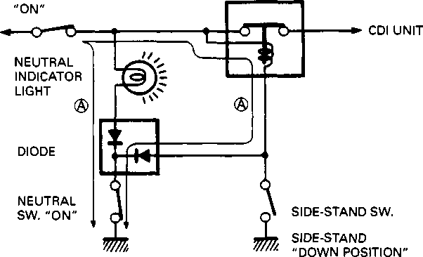 The.current flow ® turns "ON" the relay and CDI unit lives even the side-stand is kept down. This is or warming up the engine. 2. Side-stand: "UP-RIGHT (ON)"
BATTERY SIDE-STAND IGNITION SW. RELAY "ON"  The current flow (|) turns "ON" the relay and the CDI unit lives. The engine can be easily started at any transmission position. TROUBLESHOOTING
Correct
1----------------------------------------------------- ► • Poor contact of the starter relay
Check the side-stand switch. (Refer to page 6-17.) Faulty side-stand switch Incorrect Starter motor runs when the transmission is in neutral, but does not run with the transmission in any position except neutral, with the side-stand up position. Correct Open circuit in wiring harness Poor contact of connector
) ^ Others
Engine does not turn though starter motor runs. Faulty starter clutch
• Remove the exhaust pipe. • Remove the cam drive chain tensioner. • Disconnect the starter motor lead wire and remove the starter motor by removing the mounting bolts. (Refer to page 3-11.)
© O-ring © Housing end (inside) © Washer set © O-ring (2 pcs) © Starter motor case © Armature © Washer set © Brush holder ® Brush spring ® Housing end (outside)  • Disassemble the starter motor as shown in the illustration. STARTER MOTOR INSPECTION CARBON BRUSH Inspect the brushed for abnormal wear, crack or smoothness in the brush holder.
Inspect the commutator for discoloration, abnormal wear or undercut @. If the commutator is abnormally worn, replace the armature. When surface is descolored, polish it with #400 sand paper and clean it with dry cloth. If there is no undercut, scrape out the insulator ф with saw blade. ARMATURE COIL INSPECTION Check for continuity between each segment. Check for continuity between each segment and the armature shaft. If there is no continuity between the segments or there is continuity between the segments and shaft, replace the armature with a new one. OIL SEAL INSPECTION Check the seal lip for damage or leakage. If any damage is found, replace the bracket. STARTER MOTOR REASSEMBLY Reassemble the starter motor in the reverse order of disassembly. Pay attention to the following points: A CAUTION Replace the О-rings with new ones to prevent oil leakage and moisture. [54]
1РИ1  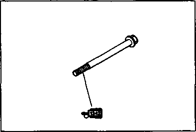 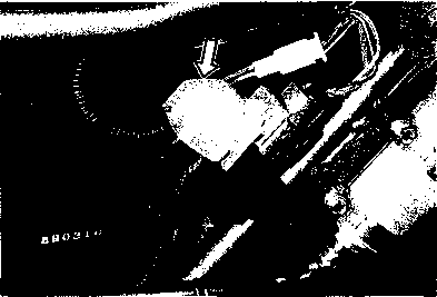 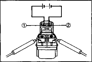 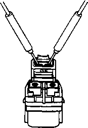 • Apply a small quantity of MOLY PASTE to the armature shaft. • Apply a small quantity of MOLY PASTE to the armature shaft.
99000-25140: SUZUKI MOLY PASTE • Apply a small quantity of THREAD LOCK "1342" to the starter motor housing bolts. tjSI 99000-32050: THREAD LOCK "1342" STARTER RELAY INSPECTION • Remove the left frame cover. • Remove the starter relay cover. • Disconnect the starter motor lead wire and battery lead wire at the starter relay. • Disconnect the lead wire coupler from the starter relay. Apply 12 volts to (D and d) terminals, inspect the continuity between the terminals, positive and negative. If the starter relay is in sound condition, continuity is found. 09900-25008: Multi circuit tester set Qp3l Tester knob indication: Continuity test (•))) ) A CAUTION___________________________________________ Do not apply a battery voltage more than 5 seconds to the starter relay as it may overheat and cause damage to the relay coil.
SIDE-STAND/IGNITION INTERLOCK SYSTEM INSPECTION If the interlock system does not operate properly, check each component. If any abnormality is found, replace the component with a new one. DIODE The diode ф is located behind the right frame cover. • Remove the seat and right frame cover. • Disconnect the diode. Using a multi circuit, tester, measure the voltage between the terminals in the following table. Unit: V
U*K« 09900-25008: Multi circuit tester set
Tester knob indication: Diode test (44- ) NOTE: If the tester read under 1.4V, replace the battery of multi circuit tester when do not connecting the tester probes. NEUTRAL SWITCH The neutral lead wire coupler is located under the fuel tank. • Remove the seat. • Disconnect the neutral switch lead and check the continuity between Blue and Ground with the transmission in "NEUTRAL". ~ ^^ Blue Ground ON (Neutral) o----------- ------ О OFF (Except neutral)
SIDE-STAND SWITCH The side-stand switch lead wire coupler is located under the fuel tank. • Remove the seat. • Disconnect the lead wire coupler. • Check the voltage between Green (® Probe) and Black/ White (© Probe) with the side-stand switch in Up-right position. If any abnormality is found, replace it with a new one. 09900-25008: Multi circuit tester set Il-T-T* iQ) Tester knob indication: Diode test (-M- )
Green (® Probe) Black/White (© Probe) ON (UP-right position) 0.4-0.6V OFF (Down position) 1.4-1.5V
NOTE: If the tester read under 1.4V, replace the battery of multi circuit tester when do not connecting the tester probes. NOTE: When replacing the side-stand switch, apply small quantity of THREAD LOCK SUPER "1342" to its mounting bolts.
SIDE-STAND/IGNITION INTERLOCK RELAY The side-stand/ignition interlock relay is located behind the right frame cover. • Remove the seats and the right frame cover. • Disconnect the lead wire coupler from the side-stand/ ignition interlock relay.
CLUTCH LEVER POSITION SWITCH ^ Yellow/Green Yellow/Green ON (Squeeze) o----------- ------ О OFF
IGNITION SYSTEM DESCRIPTION In the capacitor discharged ignition system, the electrical energy generated by the magneto charges the capacitor. This energy is released in a single surge at the specified ignition timing point, and current flows through the primary side of the ignition coil. A high voltage current is induced in the secondary windings of the ignition coil resulting in strong spark between the spark plug gap.
Ignition fuse O/Y Side-stand relay °“l O/B
Speed ometer
O/W— Engine stop switch W/BI — WIRE COLOR В : Black Bl : Blue G : Green О : Orange R : Red O/W : Orange with White tracer O/Y : Orange with Yellow tracer W/BI: White with Blue tracer Y/G : Yellow with Green tracer W : White B/W : Black with White tracer Bl/B : Blue with Black tracer O/B : Orange with Black tracer O/G : Orange with Green tracer B/W B/W  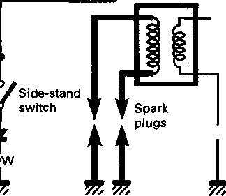 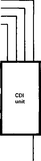
TROUBLESHOOTING Poor connection of ignition couplers.
Correct
Do not touch the tester probes and spark plugs to prevent an electric shock while testing.  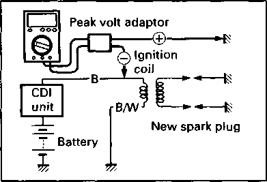  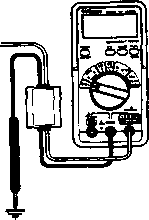 INSPECTION INSPECTION
IGNITION COIL PRIMARY PEAK VOLTAGE • Remove the fuel tank. (Refer to page 4-3.) • Remove the two spark plug caps. • Connect new two spark plugs to the each spark plug cap and ground them. NOTE: Be sure that all couplers and spark plugs are connected properly and the battery used is in fully-charged condition. Inspect the ignition coil primary peak voltage in the following procedure. • Connect the multi circuit tester with peak voltage adaptor as follow. Ignition coil: Black terminal-Ground (© Probe) (© Probe) NOTE: Do not disconnect the ignition coil primary wire. 09900-25008: Multi circuit tester set A CAUTION When using the multi circuit tester and peak volt adaptor, follow the instruction manual. [55] [56] IGNITION COIL (Checking with Electro Tester) • Remove the fuel tank. • Remove the ignition coil. NOTE: Make sure that the three-needle sparking distance of electro tester is set at 8 mm (0.3 in). With the tester and jumper wire, test the ignition coil for sparking performance in accordance with the following two steps. STEP®: Connect the jumper wire to the spark plug cap and ignition coil ground. STEP©: Switch over the jumper wire to the other plug cap and ground. If no sparking or orange color sparking occurs in the above conditions, it may be caused by defective coil. 09900-28108: Electro tester Spark performance: Over 8 mm (0.3 in)
Do not touch the wire clips to prevent an electric shock when testing. 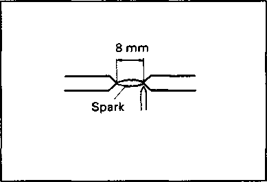 AWARNING
ПгИ1 IGNITION COIL RESISTANCE• An ohm meter may be used, instead of the electro tester. In either case, the ignition coil is to be checked for continuity in both primary and secondary windings. Exact ohmic readings are not necessary, but, if the windings are in sound condition, their continuity will be noted with these approximate ohmic values. 09900-25008: Multi circuit tester set Ignition coil resistance Primary: 0.07-0.12Q (® Black lead-© Black/white lead)
^=0 =*=>— LaJ
j
 Secondary: 23-25 kO (Plug cap-Plug cap) 0 Tester knob indication: Resistance (£2) Secondary: 23-25 kO (Plug cap-Plug cap) 0 Tester knob indication: Resistance (£2)
йлЯ1 POWER SOURCE COIL AND PICK-UP COIL• Remove the seat. • Disconnect the lead wire coupler ф from the CDI unit. • Measure each coil resistance between lead wires. If the resistance is infinity or less than the specifications, the power source coil and pick-up coil must be replaced. 09900-25008: Multi circuit tester set Power source coil resistance: 0.1-0.2Q (Yellow-White) Pick-up coil resistance: 170-256 £2 (Blue-Green)
iSHl SPARK PLUG• Remove the spark plugs. 09930-10121: Spark plug socket wrench set Carbon Deposit Check to see the carbon deposit on the plug. If the carbon is deposited, remove it with a spark plug cleaner machine or carefully using a tool with a pointed end. Spark Plug Gap Measure the plug gap with a thickness gauge if it is correct. If not, adjust it to the following gap. 09900-20803: Thickness gauge Standard: 0.7-0.8 mm (0.028-0.031 in) Electrode's Condition Check to see a worn or burnt condition of the electrode. If it is extremely worn or burnt, replace the plug. Also replace the plug if it has a broken insulator, damaged thread, etc. Heat Range NGK CR10E or NIPPONDENSO U31ESR-N should be used as the standard. However, the heat range of the spark plug should be selected to meet the requirements of speed, actual load, fuel and etc. Proper heat range would be indicated if all insulators were LIGHT BROWN in color. If they are blackened by carbon, they should be replaced with a hot type plug NGK CR9E or NIPPONDENSO U27ESR-N. '— Standard Hot type NGK CR10E CR9E NIPPONDENSO U31ESR-N U27ESR-N
A CAUTION
0.7-0.8 mm (0.028-0.031 in)  Confirm the thread size and reach when replacing the plug. If the reach is too short, carbon will be deposited on the screw portion of the plug hole and engine damage may result. Confirm the thread size and reach when replacing the plug. If the reach is too short, carbon will be deposited on the screw portion of the plug hole and engine damage may result.
COMBINATION METER REMOVAL • Remove the instrument panel. (Refer to pages 5-2 and -3.) • Remove the combination meter by removing its mounting four bolts. DISASSEMBLY
© Combination meter cover © Combination meter unit ® Combination meter case ® Bulb (12V 1.7W) © O-ring © Rubber cap 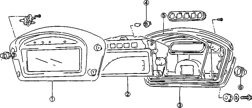
INSPECTION Using the tester, check the continuity between terminals in the following diagram. If the continuity measured is incorrect, remove and check the bulb. If the bulb is failure, install the new bulb and check the continuity again. If the bulb is correct, replace the unit with a new one.
20 19 18 17 16 15 14 13 1211
7. Blank 8. Blank 9. Blank 10. NEUTRAL © 11. BATTERY 12. SPEED VCC 13. SIGNAL GROUND 14. TURN (L) 15. HIGH BEAM 16. TURN (R) 17. FUEL 18. SPEED SIGNAL 19. TACHO 20. SPEED DISPLAY SWITCH (for E-02) ITEM © Probe of tester to: © Probe of tester to: HIGH BEAM NEUTRAL TURN (R) TURN (L) ILLUMI
If the speedometer, odometer or tripmeter does not function properly. Inspect the speed sensor and connection of couplers. If the speed sensor and connection is all right, replace the unit with a new one. SPEED SENSOR INSPECTION • Remove the front wheel. (Refer to page 5-5.) • Remove the fuel tank left cover. • Disconnect speed sensor lead wire coupler. • Remove the speed sensor by taking off its clamps. • Connect 12V battery (between O/R and B/W), 10kQ resistor (between O/R and P) and the multi circuit tester (® probe of tester to O/R and © to P) as shown right illustration. O/R : Orange with Red tracer B/W: Black with White tracer P : Pink 09900-25008: Multi circuit tester set Tester knob indication: Voltage ( ~ )
FUEL METER INSPECTION • Disconnect the fuel level gauge lead wire coupler. (Refer to page 4-4.) To test the fuel meter two different checks may be used. The first, connect a jumper wire between B/W and Y/B wires coming from the main wiring harness. With the ignition switch turned ON, the fuel meter should indicate "F". The second test will check the accuracy of the meter in the full and empty positions. Connect a new fuel level gauge as shown in the illustration. Fuel meter is normal if its display indicates the E (empty) position when the specified resistance is applied to the circuit and if its display indicates the F (full) position when the resistor is changed to the specified values. If either one or both indications are abnormal, replace the combination meter with a new one. Resistance О СЛ 88-100Q Float position Full (FJ Empty (E)
A CAUTION When inspecting the gauge resistance, be sure to disconnect the battery lead wire, or a tester may be damaged. B/BI: Black with Blue tracer B/W Black with White tracer O/G: Orange with Green tracer Y/B : Yellow with Black tracer FUEL LEVEL GAUGE REMOVAL/ INSTALLATION • Remove the fuel tank. (Refer to page 4-3.) • Remove the fuel level gauge ф by removing the bolts. • Install the fuel level gauge in the reverse order of removal. A CAUTION FUEL LEVEL GAUGE INSPECTION • Remove the fuel tank and fuel level gauge. (Refer to pages 4-3 and 6-27.) Check the resistance of each float position with multi circuit tester. If the resistance measured is incorrect, replace the fuel gauge assembly with a new one. The relation between the position of the fuel gauge float and resistance is shown in the following table. Float position Resistance Full (F) —к —к сл О Empty (E) 88-100Q SPHl
09900-25008: Multi circuit tester set Tester knob indication: Resistance (Q) LAMPS
Headlight bulb: 12V 60/55W Position light bulb: 12V 4W (Except E-24) NOTE: Adjust the headlight, both vertical and horizontal, after reassembling. HEADLIGHT AND POSITION LIGHT BULB REPLACEMENT Headlight • Disconnect the socket ф and remove the rubber cap @. • Remove the bulb (D by unlocking the bulb holder spring • Reassemble the bulb in the reverse order of removal. A CAUTION
• Remove the rubber cap ©. • Turn the socket to the left and pull it out. • Push in on the bulb, turn it to the left, and pull it out.
Turn signal light • Remove the lens by removing the screw. • Turn the socket to the left and remove it. • TURN SIGNAL RELAY The turn signal relay ф is located under the seat. If the turn signal light does not light. Inspect the bulb or repair the circuit connection. If the bulb and circuit connection checked are correct, the turn signal relay may be faulty, replace it with a new one. NOTE:
SWITCHES Inspect each switch for continuity with a tester. If any abnormality is found, replace the respective switch assemblies with new ones.
IGNITION SWITCH (For E-24) '''''■''-''--^Color Position''''-'-^ R O/Y B/W OFF
ON a— l—o a— —о LOCK
" ---^^Color Position''''-'--^ B/BI B/W •
PUSH о--------- ---------- о FRONT BRAKE SWITCH
(For others) ^^--^Color Position''^---^ R O/Y B/W Gr Br OFF
ON o- -o OH -o OH -o LOCK
P
LIGHTING SWITCH (Except E-24) ^^^^Color Position^-^ O/BI Gr Y/W OFF
• О----- ----- О
ON 0----- ----- О— ----- О
DIMMER SWITCH "~^--^Color PositiorT^^^^ Y/W w Y HI 0-----
---- О LO О---- ----- 0
TURN SIGNAL SWITCH '^'''■^-^Color Position'''---^ Lg Lbl в L
О— —о PUSH
R О------ ----- 0
PASSING LIGHT SWITCH '"'^-^^Color Positicm^--^ O/R Y •
PUSH o--------- -------- О
ENGINE STOP SWITCH "'-''"^-^Color PositiorT^-^ O/Y O/W OFF
RUN О--------- ---------- о
WIRE COLOR В : Black Br : Brown Gr : Gray Lbl : Light blue Lg : Light green О : Orange R : Red W : White Y : Yellow B/BI: Black with Blue tracer B/W: Black with White tracer O/BI: Orange with Blue tracer O/G : Orange with Green tracer O/R : Orange with Red tracer O/W: Orange with White tracer O/Y : Orange with Yellow tracer W/B: White with Black tracer Y/G : Yellow with Green tracer Y/W: Yellow with White tracer ^^-~\_Color Position'''-'--^ Y/G Y/G OFF
ON О--------- -------- О
^~~''---^Color Position'"'^'^^ O/G W/B OFF
ON О--------- ---------- о CLUTCH LEVER POSITION SWITCH
^''-''-^^^Color Position'''---^ O/G В OFF
ON О--------- -------- 0 REAR BRAKE SWITCH
STARTER BUTTON ^''~''~-^^Color PositiorT^^--^ O/W Y/G •
PUSH о--------- -------- О HORN BUTTON
BATTERY SPECIFICATIONS Upper cover breather Cathode plates Stopper Terminal Safety valve Filter Type designation YTX9-BS Capacity 12V, 28.8 kC (8 Ah)/10HR Standard electrolyte S.G. 1.320 at 20°C (68°F)
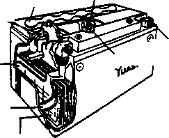
Separator (fiberglass plate) Anode plates
 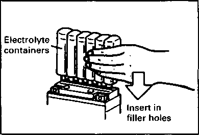 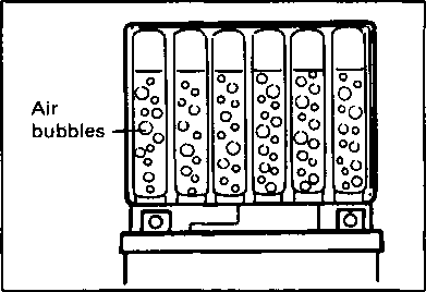 INITIAL CHARGING INITIAL CHARGING
Filling electrolyte • Remove the aluminum tape ф sealing the battery electrolyte filler holes. * Remove the caps NOTE: * After filling the electrolyte completely, use the removed cap ф as the sealed caps of battery-filler holes. * Do not remove or pierce the sealed areas d) of the electrolyte container. • Insert the nozzles of the electrolyte container into the battery's electrolyte filler holes, holding the container firmly so that it does not fall. Take precaution not to allow any of the fluid to spill. [59] NOTE: If no air bubbles are coming up from a filler port, tap the bottom of the two or three times. Never remove the container from the battery. • After confirming that the electrolyte has entered the battery completely, remove the electrolyte containers from the battery. Wait for around 20 minutes. • Insert the caps into the filler holes, pressing in firmly so that the top of the caps do not protrude above the upper surface of the battery's top cover.
• Using SUZUKI pocket tester, measure the battery voltage. The tester should indicate more than 12.5-12.6V (DC) as shown in the Fig. If the battery voltage is lower than the specification, charge the battery with a battery charger. (Refer to the recharging operation.) NOTE: Initial charging for a new battery is recommended if two years have elapsed since the date of manufacture. SERVICING
RECHARGING OPERATION • Using the pocket tester, check the battery voltage. If the voltage reading is less than the 12.0V (DC), recharge the battery with a battery charger. A CAUTION When recharging the battery, remove the battery from the motorcycle. NOTE: Do not remove the caps on the battery top while recharging. Recharging time: 4A for one hour or 0.9A for 5-10 hours A CAUTION
Time (Minutes) 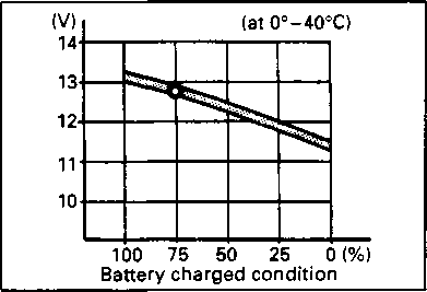 Be careful not to permit the charging current to exceed 4A at any time. [61] Be careful not to permit the charging current to exceed 4A at any time. [61]
SERVICING INFORMATION --------------------------- CONTENTS--------------------------- TROUBLESHOOTING.................................................... 7- 1 WIRING DIAGRAM .................................................... 7-8 WIRE, CABLE AND HOSE ROUTING............................... 7-10 WIRE ROUTING......................................................... 7-10 CABLE ROUTING...................................................... 7-14 CARBURETOR AND AIR CLEANER HOSE ROUTING.......... 7-16 PAIR (AIR SUPPLY) SYSTEM HOSE ROUTING ................. 7-17 FRONT BRAKE HOSE ROUTING................................... 7-18 REAR BRAKE HOSE ROUTING..................................... 7-19 FUEL TANK WATER DRAIN HOSE ROUTING.................... 7-20 OIL HOSE ROUTING................................................... 7-21 FAIRING SET-UP ...................................................... 7-22 FUEL TANK COVER SET-UP........................................ 7-22 PROTECTOR AND HEAT SHIELD ADHERING...................... 7-23 SIDE STAND SPRING SET-UP ..................................... 7-24 SPECIAL TOOLS.......................................................... 7-25 TIGHTENING TORQUE................................................ 7-28 SERVICE DATA........................................................ 7-31 TROUBLESHOOTING ENGINE Complaint Symptom and possible causes Remedy Engine will not start. Compression too low
or is hard to start. 1. Out of adjustment valve clearance. Adjust.
2. Worn valve guides or poor seating of valves. Repair or replace.
3. Mistiming valves. Adjust.
4. Excessively worn piston rings. Replace.
5. Worn-down cylinder bores. Replace or rebore.
6. Slow rotating starter motor. See electrical section.
7. Poor seating of spark plugs. Plugs not sparking Retighten.
1. Fouled spark plugs. Clean.
2. Wet spark plugs. Clean and dry.
3. Defective ignition coil. Replace.
4. Open or short in high-tension cords. Replace.
5. Defective generator or CDI unit. Replace.
6. Defective side-stand switch or side stand relay. No fuel reaching the carburetor Replace.
1. Clogged fuel tank cap. Clean or replace.
2. Clogged or defective fuel valve. Clean or replace.
3. Defective carburetor needle valve. Replace.
4. Clogged fuel hose or vacuum hose. Clean or replace.
5. Clogged fuel filter. Clean or replace. Engine stalls easily. 1. Fouled spark plugs. Clean.
2. Defective signal generator or CDI unit. Replace.
3. Clogged fuel hose. Clean.
4. Clogged jets in carburetor. Clean.
5. Out of adjustment valve clearance. Adjust. Noisy engine. Excessive valve chatter
1. Too large valve clearance. Adjust.
2. Weakened or broken valve springs. Replace.
3. Worn down rocker arm or rocker arm shaft. Replace.
4. Worn and burnt camshaft journal. Noise seems to come from piston Replace.
1. Worn down piston or cylinder. Replace.
2. Fouled with carbon combustion chamber. Clean.
3. Worn piston pins or piston pin bore. Replace.
4. Worn piston rings or ring grooves. Noise seems to come from timing chain Replace.
1. Stretched chain. Replace.
2. Worn sprocket. Replace.
3. Not working cam chain tensioner adjuster. Noise seems to come from clutch Repair or replace.
1. Worn splines of countershaft or hub. Replace.
2. Worn teeth of clutch plates. Replace.
3. Distorted clutch plates, driven and drive. Replace.
4. Worn clutch release bearing. Replace.
5. Weakened clutch dampers. Replace the primary driven gear.
Complaint Symptom and possible causes Remedy Noisy engine. Noise seems to come from crankshaft
1. Due to wear rattling bearings. Replace.
2. Worn and burnt big-end bearings. Replace.
3. Too large thrust clearance. Replace conrod.
Noise seems to come from transmission
1. Worn or rubbing gears. Replace.
2. Badly worn splines. Replace.
3. Worn or rubbing primary gears. Replace.
4. Badly worn bearings. Replace. Slipping clutch. 1. Out of adjustment or loss of play clutch control. Adjust.
2. Weakened clutch springs. Replace.
3. Worn or distorted pressure plate. Replace.
4. Distorted clutch plates, driven and drive. Replace. Dragging clutch. 1. Clutch control out of adjustment or loss of play. Adjust
2. Some clutch springs weakened while others are not. Replace.
3. Distorted pressure plate or clutch plates. Replace. Transmission will 1. Broken gearshift cam. Replace. not shift. 2. Distorted gearshift forks. Replace.
3. Worn gearshift pawl. Replace. Transmission will 1. Broken return spring on shift shaft. Replace. not shift back. 2. Rubbing or stickly shift shaft. Repair or replace.
3. Distorted or worn gearshift forks. Replace. Transmission jumps 1. Worn shifting gears on driveshaft or countershaft. Replace. out of gear. 2. Distorted or worn gearshift forks. Replace.
3. Weakened stopper spring on gearshift cam. Replace.
4. Worn gearshift pawl. Replace. Engine idles poorly. 1. Out of adjustment valve clearance. Adjust.
2. Poor seating of valves. Replace or repair.
3. Defective valve guides. Replace.
4. Worn rocker arms or arm shafts. Replace.
5. Too wide spark plug gaps. Adjust or replace.
6. Defective ignition coil. Replace.
7. Defective generator or CDI unit. Replace.
8. Out of adjustment in carburetor float-chamber fuel Adjust.
level.
9. Clogged jets. Clean.
Complaint Symptom and possible causes Remedy Engine runs poorly in 1. Weakened valve springs. Replace. high speed range. 2. Worn camshafts. Replace.
3. Valve timing out of adjustment. Adjust.
4. Too narrow spark plug gaps. Adjust.
5. Ignition not advanced sufficiently due to poorly working timing advance circuit. Replace CDI unit.
6. Defective ignition coil. Replace.
7. Defective generator or CDI unit. Replace.
8. Too low float-chamber fuel level. Adjust.
9. Clogged air cleaner element. Clean.
10. Clogged fuel hose, resulting in inadequate fuel supply to carburetor. Clean and prime. Dirty or heavy exhaust smoke. 1. Too much engine oil in the engine. Check with inspection window drain out excess oil.
2. Worn piston rings or cylinder. Replace.
3. Worn valve guides. Replace.
4. Scuffed cylinder wall. Replace.
5. Worn valves stems. Replace.
6. Defective stem seal. Replace.
7. Worn oil ring side rails. Replace. Engine lacks power. 1. Loss of valve clearance. Adjust.
2. Weakened valve springs. Replace.
3. Out of adjustment valve timing. Adjust.
4. Worn piston rings or cylinder. Replace.
5. Poor seating of valves. Repair.
6. Fouled spark plug. Clean or replace.
7. Incorrect spark plug. Adjust or replace.
8. Clogged jets in carburetor. Clean.
9. Out of adjustment float-chamber fuel level. Adjust.
10. Clogged air cleaner element. Clean.
11. Sucking air from intake pipe. Retighten or replace.
12. Too much engine oil. Drain out excess oil.
13. Diffective generator, CDI unit or ignition coil. Replace. Engine overheats. 1. Heavy carbon deposit on piston crown. Clean.
2. Not enough oil in the engine. Add oil.
3. Defective oil pump or clogged oil circuit. Replace or clean.
4. Too low in float chamber fuel level. Adjust.
5. Sucking air from intake pipes. Retighten or replace.
6. Use incorrect engine oil. Change.
7. Oil cooler. Clean.
CARBURETOR Complaint Symptom and possible causes Remedy Trouble with 1. Clogged starter jet. Clean. starting. 2. Clogged starter pipe. Clean.
3. Air leaking from a joint between starter body and Check starter body and
carburetor. carburetor for tightness, adjust and replace gasket.
4. Air leaking from carburetor's joint or vacuum gauge joint. Check and adjust.
5. Not operation properly starter plunger. Check and adjust. Idling or low-speed 1. Clogged or loose pilot jet, pilot air jet. Check and clean. trouble. 2. Air leaking from carburetor's joint, vacuum hose joint, or starter. Check and adjust.
3. Clogged pilot outlet or bypass. Check and clean.
4. Not fully closed starter plunger. Check and adjust. Medium-or high 1. Clogged main jet or main air jet. Check and clean. speed trouble. 2. Clogged needle jet. Check and clean.
3. Not operating properly throttle valve. Check throttle valve for operation.
4. Clogged fuel filter. Check and clean. Overflow and fuel 1. Worn or damaged needle valve. Replace. level fluctuations. 2. Broken spring in needle valve. Replace.
3. Not working properly float. Check and adjust.
4. Foreign matter has adhered to needle valve. Clean.
5. Too high or low fuel level. Adjust float height.
CHASSIS Complaint Symptom and possible causes Remedy Heavy steering. 1. Overtightened steering stem nut. Adjust.
2. Broken bearing in steering stem. Replace.
3. Distorted steering stem. Replace.
4. Not enough pressure in tires. Adjust. Wobbly handlebars. 1. Loss of balance between right and left front forks. Replace.
2. Distorted front fork. Repair or replace.
3. Distorted front axle or crooked tire. Replace. Wobbly front wheel. 1. Distorted wheel rim. Replace.
2. Worn front wheel bearings. Replace.
3. Defective or incorrect tire. Replace.
4. Loose axle or axle holder nuts. Retighten.
5. Incorrect front fork oil level. Adjust. Front suspension 1. Weakened springs. Replace. too soft. 2. Not enough fork oil. Replenish. Front suspension 1. Too viscous fork oil. Replace. too stiff. 2. Too much fork oil. Drain excess oil. Noisy front 1. Not enough fork oil. Replenish. suspension. 2. Loose bolts and nuts on suspension. Retighten.
Complaint Symptom and possible causes Remedy Wobbly rear wheel. 1. Distorted wheel rim. Replace.
2. Worn rear wheel bearings or swingarm bearings. Replace.
3. Defective or incorrect tire. Replace.
4. Worn swingarm and rear suspension related bearings. Replace.
5. Loose nuts or bolts on rear suspensions. Retighten. Rear suspension too 1. Weakened shock absorber spring. Replace. soft. 2. Improperly set rear suspension adjuster. Adjust.
3. Leakage oil of shock absorber. Replace. Rear suspension too 1. Improperly set rear suspension adjuster. Adjust. stiff. 2. Bent shock absorber shaft. Replace.
3. Bent swingarm. Replace.
4. Worn swingarm and rear suspension related bearings. Replace. Noisy rear 1. Loose nuts or bolts on rear suspension. Retighten. suspension. 2. Worn swingarm and rear suspension related bearings. Replace.
BRAKES Complaint Symptom and possible causes Remedy Insufficient brake 1. Leakage of brake fluid from hydraulic system. Repair or replace. power. 2. Worn pads. Replace.
3. Oil adhesion of engaging surface of pads. Clean disc and pads.
4. Worn disc. Replace.
5. Air in hydraulic system. Bleed air. Brake squeaking. 1. Carbon adhesion on pad surface. Repair surface with sandpaper.
2. Tilted pad. Modify pad fitting or replace.
3. Damaged wheel bearing. Replace.
4. Loosen front-wheel axle or rear-wheel axle. Tighten to specified torque.
5. Worn pads. Replace.
6. Foreign material in brake fluid. Replace brake fluid.
7. Clogged return port of master cylinder. Disassemble and clean master cylinder. Excessive brake 1. Air in hydraulic system. Bleed air. lever or pedal stroke. 2. Insufficient brake fluid. Replenish fluid to specified level; bleed air.
3. Improper quality of brake fluid. Replace with correct fluid. Leakage of brake 1. Insufficient tightening of connection joints. Tighten to specified fluid.
torque.
2. Cracked hose. Replace.
3. Worn piston and/or cup. Replace piston and/or cup.
ELECTRICAL Complaint Symptom and possible causes Remedy No sparking or poor 1. Defective ignition coil. Replace. sparking. 2. Defective spark plugs. Replace.
3. Defective generator or CDI unit. Replace. Spark plug soon 1. Mixture too rich. Adjust carburetor. become fouled with 2. Idling speed set too high. Adjust carburetor. carbon. 3. Incorrect gasoline. Change.
4. Dirty element in air cleaner. Clean.
5. Too cold spark plugs. Replace with hot type plugs. Spark plugs become 1. Worn piston rings. Replace. fouled too soon. 2. Worn piston or cylinder. Replace.
3. Excessive clearance of valve stems in valve guides. Replace.
4. Worn stem oil seal. Replace. Spark plug 1. Too hot spark plugs. Replace with cold type electrodes overheat
plugs. or burn. 2. Overheated the engine. Tune up.
3. Loose spark plugs. Retighten.
4. Too lean mixture. Adjust carburetor. Generator does not 1. Open or short lead wires, or loose lead connections. Repair or replace or charge.
retighten.
2. Shorted, grounded or open generator coils. Replace.
3. Shorted or panctured regulator/rectifier. Replace. Generator does 1. Lead wires tend to get shorted or open-circuited or Repair or retighten. charge, but charging loosely connected at terminals.
rate is below the 2. Grounded or open-circuited stator coils or generator. Replace. specification. 3. Defective regulator/rectifier. Replace.
4. Defective cell plates in the battery. Replace the battery. Generator 1. Internal short-circuit in the battery. Replace the battery. overcharges. 2. Damaged or defective regulator/rectifier. Replace.
3. Poorly grounded regulator/rectifier. Clean and tighten ground connection. Unstable charging. 1. Lead wire insulation frayed due to vibration, resulting in intermittent shorting. Repair or replace.
2. Internally shorted generator. Replace.
3. Defective regulator/rectifier. Replace. Starter button is not 1. Run down battery. Repair or replace. effective. 2. Defective switch contacts. Replace.
3. Not seating properly brushes on commutator in starter motor. Repair or replace.
4. Defective starter relay/starter interlock switch. Replace.
BATTERY Complaint Symptom and possible causes Remedy "Sulfation", acidic 1. Cracked battery case. Replace the battery. white powdery substance or spots on surfaces of cell plates. 2. Battery has been left in a run-down condition for a long time. Replace the battery. Battery runs down quickly. 1.Not correct the charging system. 2.Cell plates have lost much of their active material as a result of overcharging. 3.A short-circuit condition exists within the battery. 4.Too low battery voltage. 5.Too old battery. Check the generator, regulator/rectifier and circuit connections and make necessary adjustments to obtain specified charging operation. Replace the battery, and correct the charging system. Replace the battery. Recharge the battery fully. Replace the battery. Battery "sulfation". 1.Too low or too high charging rate. (When not in use batteries should be checked at least once a month to avoid sulfation.) 2.Left unused the battery for too long in cold climate. Replace the battery. Replace the battery, if badly sulfated. Battery discharges too rapidly. Dirty container top and sides. Clean.
WIRING DIAGRAM 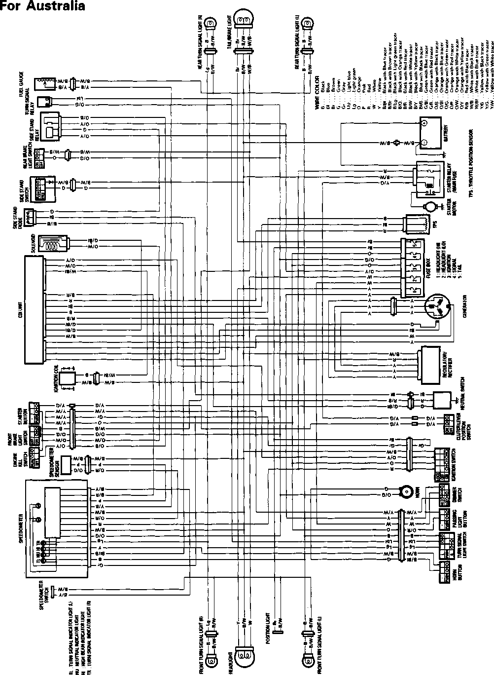
For the other market 
WIRE, CABLE AND HOSE ROUTING
Speedometer Clamp Wiring harness Front turn signal (L) Position light Pass the position light lead wire inside the brace. Clamp Wiring harness 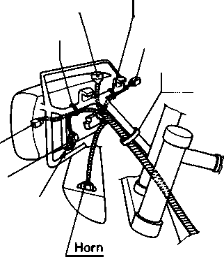 |Front turn signal (R) Clamp Wiring harness 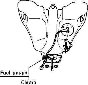 WIRE ROUTING Throttle cables
Clamp Handlebar switch (L)
Speed sensor Clutch cable Starter cable ^'amP Wiring harness Wiring harness Handlebar switch (L) Clutch lever position switch Speed sensor Clamp High-tension cord (long cord with protector)  Clamp Clamp Rear turn signal (L) Battery © Clamp Clamp 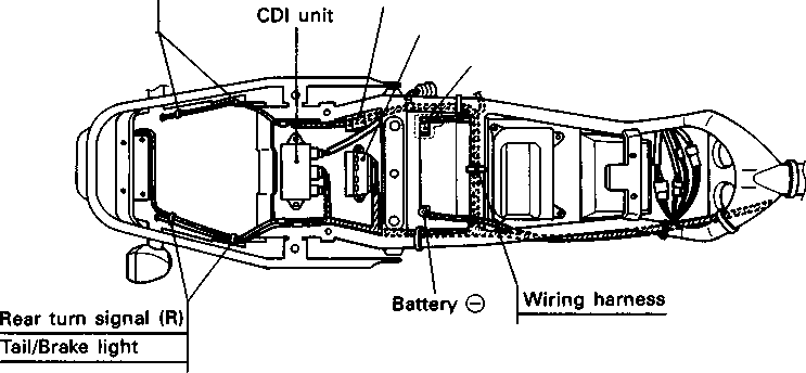 Turn signal relay Fuse box Clutch lever position switch Set the clutch lever position switch lead wire coupler between the frame and fuel tank. Taping clamp (fix to frame) High-tension cord (short cord with no protector)
Handlebar switch (R)
Clamp
Clamp
Clamp Wiring harness Rear brake light switch
Clamp 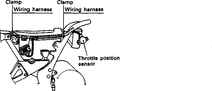
Starter motor Starter motor lead wire IFront brake hose !15 mm (0.6 in) |80-90 mm (3.2-3.6 in) {Speed sensor lead wire ICIamp the speed sensor lead wire jat the white painted mark. Clamp the speed isensor lead wire at the white painted mark. Clamp the brake hose and speed sensor lead wire at the white painted marks. Cut the surplus of clamp. iCIamp to upper side. iCIamp Generator cover 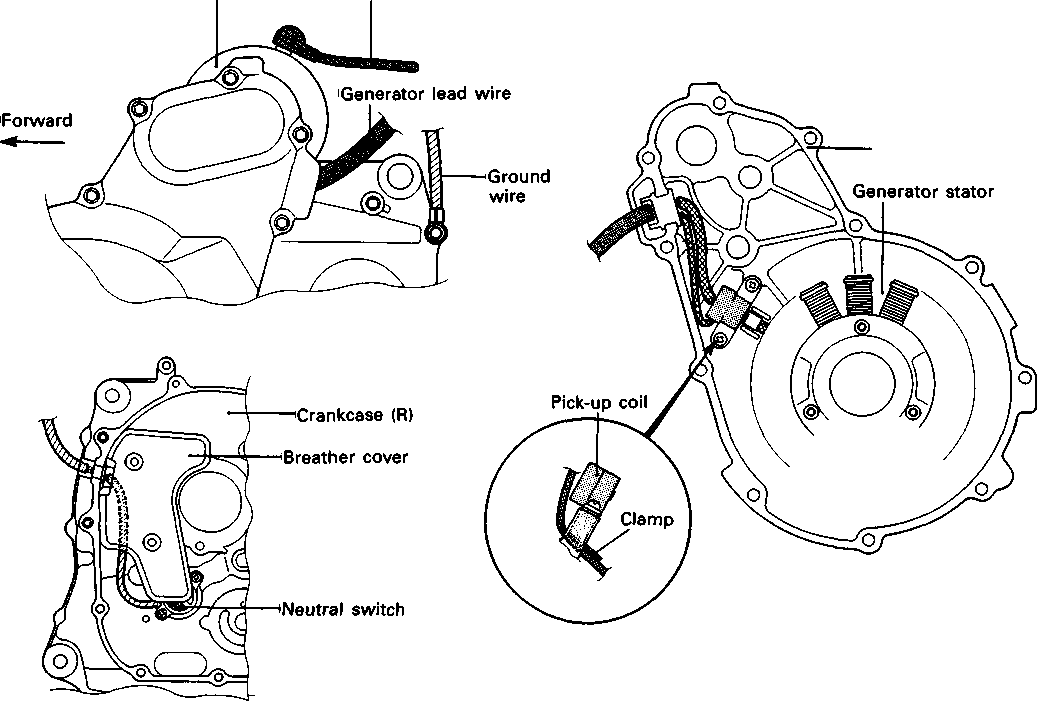  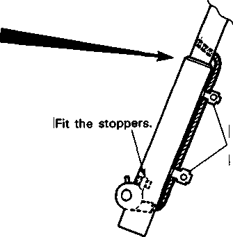
CABLE ROUTING Clutch cable Clutch cable Pass through the clutch cable in back of air control hose/ Pass through the clutch cable upper the wiring harness. 2-3 mm (0.08-0.12 in) Clamp in back of the fuel tank cushion. Throttle cable (pulling) Air control hose' Rubber boot Clamp Clutch cable 
Clutch cable Throttle cables Handlebar switch (R) Throttle cable (pulling) Guide Air control hose Pass through the clutch cable upper the air control hose. Clutch cable Air vent hose Handlebar switch (L)_______ Clutch lever position sensor Guide 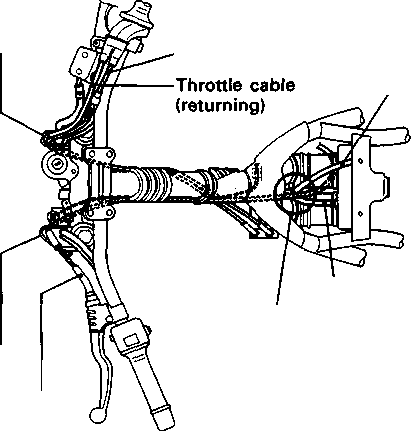 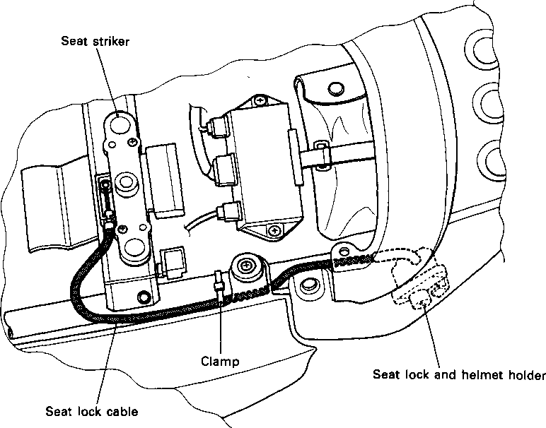
CARBURETOR AND AIR CLEANER HOSE ROUTING To fuel valve Clamp Throttle cable Vacuum chamber Crankcase Clamp Pass through the breather hoses -inside of the throttle cables. Crankcase breather hose RH Pass through the air control hoses in front Clutch cable of the clutch cable. Crankcase breather hose Vacuum hose Pass through the vacuum hose inside of air control hose. Throttle position sensor Solenoid valve Carburetor clamp position LH- -►RH Air cleaner side Starter cable Pass through the breather hoses under the starter cable. Pass through the air control hoses inside of the throttle position sensor lead wire. Air control hose. Carburetor clamp position Vacuum hose I Pass through the vacuum hose under the breather, hoses. Air cleaner drain hose Pass through the air cleaner drain hose inside of the swingarm. Starter cable Pass through the breather hose under the High-tension cord. Clutch cable .. ... Vacuum hose Air соп*г°1 hose Air vent hose   
INq PAIR (AIR SUPPLY) SYSTEM HOSE ROUT) (For Austria and Switzerland)
through the PAIR hose between th** pAlFi c°nf/ roi valv. . »-vt ft control valve vacu the engine mountir'^ PAl**r Pipe “Wf rn Air “*«'»«>■' ""«i' 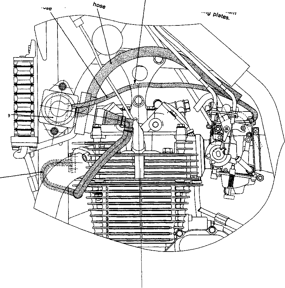 
FRONT BRAKE HOSE ROUTING
jPass the brake hose and throttle cables through the guide. After touching the brake hose union to the stopper, tighten the union bolt to the specified torque. Washer IBrake hose union bolt Throttle cables 
REAR BRAKE HOSE ROUTING
Set the brake hose to the hose guide. 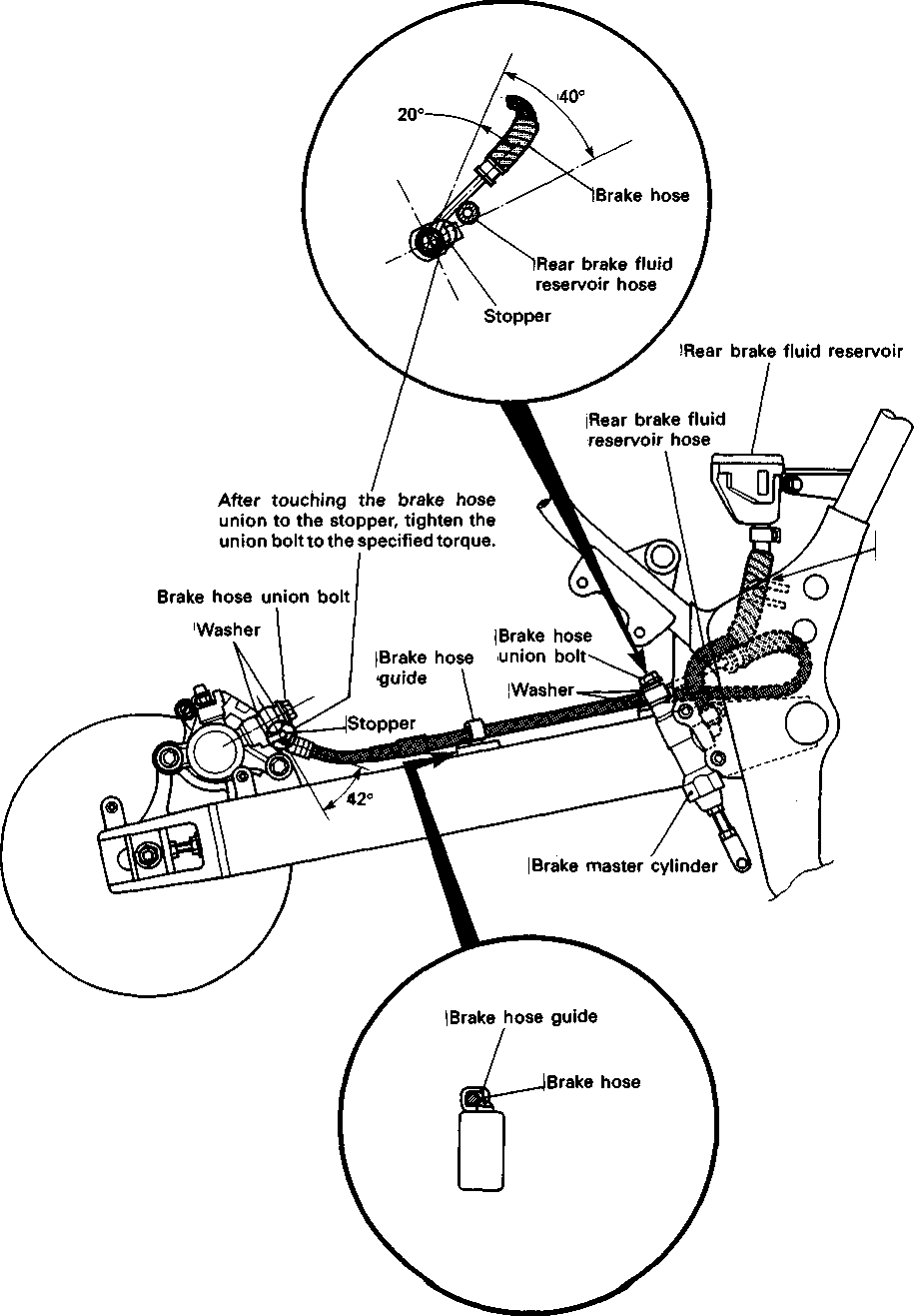
< о > IS) а СЛ  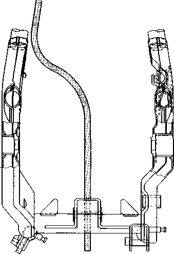
OIL HOSE ROUTING 
FAIRING SET-UP
'Speedometer panel
FUEL TANK COVER SET-UP
PROTECTOR AND HEAT SHIELD ADHERING Front  
Protector
SIDE STAND SPRING SET-UP Protector

SPECIAL TOOLS 09900-00410 Hexagon bit wrench set 09900-06108 Snap ring pliers 09900-20102 Vernier calipers 09900-22301 Plastigauge 09913-60910 Bearing/gear puller 09900-20606 Dial gauge (1/100) 09910-33210 Attachment 09900-20204 Micrometer (75-100 mm) 09900-28108 Electro tester 09913-75830 Bearing installer 09900-20803 Thickness gauge 09913-10720 Compression gauge attachment 09900-20508 Cylinder bore gauge set 09900-20513 Gauge rod 94 mm 09910-32830 Crankshaft installer attachment 09915-74510 Oil pressure gauge 09913-50121 Oil seal remover 09900-21304 V-block (100 mm) 09915-64510 Compression gauge 09910-32812 Crankshaft installer 09900-20205 Micrometer (0-25 mm) 09910-60611 Universal clamp wrench
09900-20701 Magnetic stand 09913-75810 Bearing installer
09900-25008 Multi circuit tester set 09900-20202 Micrometer (25-50 mm) 09910-32860 Crankshaft installer attachment 09900-20605 Dial calipers 09900-09004 Impact driver set 09900-06107 Snap ring pliers
09900-00401 "L" type hexagon wrench set    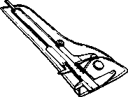  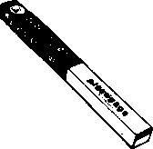  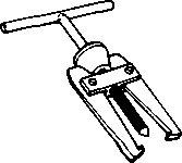        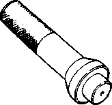 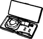      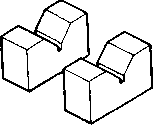   
09916-14510 Valve spring compressor 09916-14910 Valve spring compressor attachment 09916-24«^ Solid pilot 09916-24810 Valve seat cutter head 30x45° (N-626) 09916-27720 Valve seat cutter head 15x45° (N-229)
09916-34542 Reamer handle 09916-34550 5.5 mm reamer 09916-34580 10.8 mm reamer \ 09916-44910 Valve guide remover 09916-24900 Valve seat cutter set 09916-84511 Tweezers 09917-23711 Ring nut socket wrench 09920-13120 Crankcase separator/ crankshaft remover 09920-53740 Clutch sleeve hub holder 09923-73210 Bearing remover 09923-74510 Bearing remover 09924-84510 Bearing installer set 09924-84521 Bearing installer set 09925-18010 Steering bearing installer 09930-11920 Torx bit JT40H 09930-11940 Torx bit holder 09930-30102 Sliding shaft 09930-30721 Generator rotor remover I] 0 09930-73110 Starter torque limiter holder 09930-73120 Starter torque limiter socket Steering nut socket wrench 09940-14960 Steering nut wrench socket 09940-34520 "T" handle 09940-34592 Attachment G 09940-52861 Front fork oil seal installer
TIGHTENING TORQUE ENGINE ITEM N-m kg-m Ib-ft Cylinder head cover bolt 1.0 7.0 Camshaft sprocket bolt 1.5 11.0 Cylinder head bolt 3.8 27.5 Cylinder head nut 2.5 18.0 Cylinder base nut 1.0 7.0 Cam chain tensioner fitting bolt 1.3 9.5 Generator rotor bolt 16.0 115.5 Can chain tensioner adjuster mounting bolt 1.0 7.0 Spark plug 1.1 8.0 Crankcase bolt 1.1 8.0 Valve timing inspection plug 2.3 16.5 Oil gallery 2.3 16.5 Oil nozzle bolt 1.0 7.0 Magneto cover plug 1.5 11.0 Starter clutch bolt 2.5 18.0 Primary drive gear nut 10.0 72.5 Clutch spring mounting bolt 1.0 7.0 Clutch sleeve hub nut 5.0 36.0 Gearshift arm stopper 1.9 13.5 Engine oil drain plug 2.3 16.5 Engine sprocket bolt 0.6 4.5 Engine mounting bolt 8 mm Diam. 4.0 29.0 Engine mounting bolt 10 mm Diam. 6.5 47.0 Engine mounting (Upper and Front) 4.0 29.0 bracket bolt (Rear) 2.3 16.5 Exhaust pipe bolt 2.6 19.0 Muffler mounting bolt 2.6 19.0 Crankshaft bearing ring nut 8.0 58.0 Engine oil pipe union bolt (Cylinder head) 2.3 16.5 (Crankcase) 2.0 14.5 Engine oil cooler hose bolt 1.0 7.0 Cam chain tensioner adjuster cap bolt 0.6 4.5
CHASSIS ITEM N ■ m kg-m Ib-ft Front axle 6.5 47.0 Front axle holder bolt 2.3 16.5 Front fork damper rod bolt 3.0 21.5 Front fork lower clamp bolt 2.3 16.5 Front fork upper clamp bolt 2.9 21.0 Front fork cap bolt 2.3 16.5 Steering stem head nut 9.0 65.0 Handlebar clamp bolt 2.3 16.5 Handlebar holder set nut 2.5 18.0 Front brake master cylinder mounting bolt 1.0 7.0 Front brake caliper mounting bolt 3.9 28.0 Brake hose union bolt (Front & Rear) 2.3 16.5 Brake air bleeder valve (Front & Rear) 0.8 6.0 Brake disc mounting bolt (Front & Rear) 2.3 16.5 Swingarm pivot nut 7.7 55.5 Front footrest bracket mounting bolt 5.5 40.0 Rear footrest bracket mounting bolt 2.3 16.5 Rear brake master cylinder mounting bolt 1.0 7.0 Rear brake master cylinder rod lock nut 1.8 13.0 Rear brake caliper mounting bolt 2.3 16.5 Rear brake pad mounting bolt 1.8 13.0 Rear shock absorber bolt (Upper & Lower) 4.5 32.5 Rear cushion lever nut (Front) 8.0 58.0 Rear cushion lever nut (Center) 10.0 72.5 Rear cushion rod nut 10.0 72.5 Rear axle nut 11.0 79.5 Rear sprocket mounting nut 2.7 19.5 Spoke nipple (Front & Rear) 4.5 0.45 3.0
TIGHTENING TORQUE CHART For other bolts and nuts listed previously, refer to this chart: Bolt Diameter ® (mm) Conventional or "4" marked bolt "7" marked bolt N ■ m kg-m Ib-ft N ■ m kg-m Ib-ft 1.5 0.15 1.0 2.3 0.23 1.5 0.3 2.0 4.5 0.45 3.0 5.5 0.55 4.0 1.0 7.0 1.3 9.5 2.3 16.5 2.9 21.0 5.0 36.0 4.5 32.5 8.5 61.5 6.5 47.0 13.5 97.5 10.5 76.0 21.0 152.0 16.0 115.5 24.0 173.5
SERVICE DATA VALVE + GUIDE LIMIT IN. STANDARD (1.4) (1.2) IN. EX. IN. 0.17-0.22 (0.0067-0.0087) 0.010-0.037 (0.0004-0.0015) 0.030-0.057 (0.0012-0.0022) IN. & EX. Valve guide I.D. Valve stem O.D. EX. Valve stem runout Valve head thickness Valve stem end length 0.05 (0.002) 0.5 (0.02) 2.7 (0.11) IN. & EX. Valve head radial runout Valve spring free length (IN. & EX.) 0.03 (0.001) 34.4 (1.35) 38.1 (1.50) INNER OUTER 13.8-15.8 kg 5.9 —6.7 kg Valve spring tension (IN. & EX.) OUTER INNER IN. & EX. 0.9-1.1 Valve seat width IN. & EX. IN. & EX. IN. & EX. 5.500-5.512 (0.2165-0.2170) 5.475-5.490 (0.2156-0.2161) 5.455-5.470 (0.2148-0.2154) IN. IN. & EX. 0.35 (0.014) Valve stem deflection EX. Valve guide to valve stem clearance 0.08-0.13 (0.003-0.005) Valve clearance (when engine is cold) EX. ITEM Valve diam. Unit: mm (in)
CAMSHAFT + CYLINDER HEAD Unit: mm (in) ITEM STANDARD LIMIT Cam height IN. 33.690-33.758 (1.3264-1.3291) 33.390 (1.3146) EX. 33.680-33.748 (1.3260-1.3287) 33.380 (1.3142) Camshaft journal oil clearance Right & Center 0.032-0.066 (0.0013-0.0026) 0.150 (0.0059) Left 0.028-0.059 (0.0011-0.0023) 0.150 (0.0059) Camshaft journal holder I.D. Right & Center 22.012-22.025 (0.8666-0.8671)
Left 17.512-17.525 (0.6894-0.6900)
Camshaft journal O.D. Right & Center 21.959-21.988 (0.8645-0.8657)
Left 17.466-17.492 (0.6877-0.6887)
Camshaft runout
0.10 (0.004) Rocker arm I.D. IN. & EX. 12.000-12.018 (0.4724-0.4731)
Rocker arm shaft O.D. IN. & EX. 11.973-11.984 (0.4714-0.4718)
Cylinder head distortion
0.05 (0.002) Cylinder head cover distortion
0.05 (0.002)
CYLINDER-)-PISTON + PISTON RING Unit: mm (in) ITEM STANDARD LIMIT Piston to cylinder clearance 0.020-0.030 (0.0008-0.0012) 0.120 (0.0047) Cylinder bore 100.000-100.015 (3.937-3.9376) Nicks or Scratches Piston diam. 99.975-99.990 (3.9360-3.9366) Measure at 21 mm (0.8 in) from the skirt end. 99.880 (3.9323) Cylinder distortion
0.05 (0.002) Piston ring free end gap 1st R Approx. (0^53) 10.8 (0.43)
2nd R л 11.4 Approx. {045) 9.1 (0.36) Piston ring end gap 1st 0.30-0.45 (0.012-0.018) 0.50 (0.020)
2nd 0.45-0.60 (0.018-0.024) 1.00 (0.039) Compression pressure (Automatic decomp, actuated) Approx. 850 kPa /8.5 kg/cm2\ V 120 psi /
ITEM STANDARD LIMIT Piston ring to groove clearance 1st
0.180 (0.0071) 2nd
0.150 (0.0059) Piston ring groove width 1st 1.230-1.250 (0.048-0.049)
2nd 1.210-1.230 (0.047-0.048)
Oil 2.810-2.830 (0.110-0.111)
Piston ring thickness 1st 1.170-1.190 (0.0461-0.0469)
2nd 1.150-1.170 (0.0453-0.0461)
Piston pin bore 23.002-23.008 (0.9056-0.9058) 23.030 (0.9067) Piston pin O.D. 22.992-23.000 (0.9052-0.9055) 22.980 (0.9047)
CONROD + CRANKSHAFT Unit: mm (in) ITEM STANDARD LIMIT Conrod small end I.D. 23.017-23.025 (0.9062-0.9065) 23.040 (0.9071) Conrod deflection
3.0 (0.12) Conrod big end side clearance 0.10-0.65 (0.004-0.026) 1.00 (0.039) Conrod big end width 24.95-25.00 (0.982-0.984)
Crankshaft runout
0.08 (0.003) Crank web to web width 71.0 ± 0.1 (2.795 ± 0.004)
OIL PUMP ITEM STANDARD LIMIT Oil pump reduction ratio 1.633 (61/28 x 30/20 x 15/30)
Oil pressure (at 60°C,140°F) Above 30 kPa (0.3 kg/cm2, 4.3 psi) Below 70 kPa (0.7 kg/cm2, 10.0 psi) at 3 000 r/min
CLUTCH Unit: mm (in) ITEM STANDARD LIMIT Clutch lever play 10-15 (0.4—0.6)
Drive plate thickness No.1 & 2.9-3.1 2.6 No.2 (0.11-0.12) (0.10) Driven plate distortion
0.10 (0.004) Clutch spring free length
33.0 (1.30) Unit: mm (in) Except ratio
TRANSMISSION + DRIVE CHAIN LIMIT Shift fork groove width Shift fork thickness Drive chain slack 4.8—4.9
(0.189- -0.193)
Type DAIDO:DID525V9
Links
20-pitch length
319.4 (12.57)
20-30 (0.8-1.2) Drive chain STANDARD 2.178 (61/28) 2.866 (43/15) 2.416 (29/12) 1.625 (26/16) 1.238 (26/21) 1.000 (21/21) 0.826 (19/23) 0.10-0.30 (0.004-0.012) 5.0 —5.1 0.50 (0.020) ITEM Primary reduction ratio Final reduction ratio Gear ratios Low 2nd 3rd 4th ____________________ Top Shift fork to groove clearance
CARBURETOR ITEM SPECIFICATION E-02,04,17,22,24,25,34 E-18 Carburetor type MIKUNI BSR32SS «— Bore size 32 mm «— I.D. No. 04F0 04F1 Idle r/min. 1 500± 100 r/min. 1 500± 50 r/min. Float height 13.0± 1.0 mm (0.51 ±0.04 in) «— Main jet (M.J.) #115
Jet needle (J.N.) 5DH23-53-3rd
Needle jet (N.J.) P-0
Throttle valve (Th.V.) #90
Pilot jet (P.J.) #20
Starter jet (G.S.) #57.5
Pilot screw (P.S.) PRE-SET (3 turns back)
Throttle cable play (pulling cable) 0.5 — 1.0 mm (0.02-0.04 in)
Starter cable play 0.5 — 1.0 mm (0.02-0.04 in)
CARBURETOR ITEM SPECIFII CATION U-type E-22 E-37 Carburetor type MIKUNI BSR32SS
Bore size 32 mm «— I.D. No. 04F3 04F4 Idle r/min. 1 500± 100 r/min. «— Float height 13.0± 1.0 mm (0.51 ±0.04 in)
Main jet (M.J.) #115
Jet needle (J.N.) 5DH23-53-3rd
Needle jet (N.J.) P-0
Throttle valve (Th.V.) #90
Pilot jet (P.J.) #20
Starter jet (G.S.) #57.5 #62.5 Pilot screw (P.S.) PRE-SET (3 turns back)
Throttle cable play (pulling cable) 0.5—1.0 mm (0.02-0.04 in)
Starter cable play 0.5— 1.0 mm (0.02-0.04 in)
ELECTRICAL Unit: mm (in) ITEM SPECIFICATION NOTE Ignition timing 10° B.T.D.C at 1 500 r/min.
Spark plug Type ND.: U31ESR-N N.G.K.: CR10E
Gap 0.7—0.8 (0.028-0.031)
Spark performance Over 8 (0.3) at 1 atm.
Ignition coil resistance Primary 0.07-0.12 Q B-B/W Secondary 23-25 kfl Plug cap— Plug cap Generator coil resistance Charging 0.5—0.9 fl Y-Y Power source 0.1-0.2 fl B-W Pick-up 170-256 fl Bl-G Generator no-load voltage More than 75 V(AC) at 5 000 r/min.
Generator Max. output Approx. 200W at 5 000 r/min.
Regulated voltage 13.0-16.0 V at 5 000 r/min.
Starter relay resistance 3-5 fl
Battery Type designation YTX9-BS
Capacity 12V 28.8 kC (8АЫ/10 HR Standard electrolyte S.G. 1.320 at 20°C (68°F) Fuse size Main 30 A
Headlight (H) 15 A
Headlight (L) 15 A
Ignition 10 A
Signal 15 A
Tail 10 A
WATTAGE Unit:W ITEM SPECIFII CATION E-24 The others Headlight HI <- LO <- Parking or position light ____________________ Tail/Brake light 5/21 <- Turn signal light <- Speedometer light 1.7x2 <- Turn signal indicator light 1.7x2 <- High beam indicator light 1.7 <- Neutral indicator light 1.7
Unit: mm (in) Brake disc thickness Rear LIMIT 4.0 4.0 0.30 Front Master cylinder piston diam. Rear Front Brake caliper piston diam. Rear Wheel rim runout Radial Front Tire size Rear Front Rear Front Rear Front J19 x MT2.50 3.0 (0.12) 3.0 Rear 2.0 (0.08) 2.0 (0.08) 0.25 (0.010) 0.25 (0.010) Tire tread depth Tire rim size Wheel axle runout Axial 12.700-12.743 (0.5000-0.5017) 14.000-14.043 (0.5511-0.5528) 12.657-12.684 (0.4983-0.4994) 13.957-13.984 (0.5494-0.5505) 30.230-30.306 (1.1902-1.1931) 38.18-38.23 (1.503-1.505) 30.15-30.20 (1.187-1.189) 38.08-38.13 (1.499-1.501) Front Rear Brake caliper cylinder bore Front Rear Master cylinder bore Brake disc runout STANDARD_______ (0.2)__________________ 4.5 ± 0.2 (0.177 ± 0.008) 4.5 ± 0.2 (0.177 ± 0.008) Front BRAKE + WHEEL __________ ITEM Rear brake pedal height
SUSPENSION Unit: mm (in) ITEM STANDARD LIMIT NOTE Front fork stroke (6.7)
(5.5)
Low seat Front fork spring free length
(14.6)
Front fork oil level (5.6)
CM CO 0)00
Low seat Rear shock absorber spring pre-set length 169.2 (6.7)
Rear wheel travel (6.6)
i J CO • !£ ! s
Low seat Swingarm pivot shaft runout
0.3 (0.01)
TIRE PRESSURE COLD INFLATION TIRE PRESSURE SO LO RIDING DUAL RIDING kPa kg/cm2 psi kPa kg/cm2 psi FRONT 1.75 1.75 REAR 2.00 2.25
FUEL + OIL ITEM SPECIFICATION NOTE Fuel type Gasoline used should be graded 85-95 octane or higher. An unleaded gasoline is recommended.
Fuel tank including 18.5 L (4.9/4.1 US/Imp gal)
reserve 4.5 L (1.2/1.0 US/Imp gal)
Engine oil type SAE 10W/40, API SF or SG
Engine oil capacity Change 2 300 ml (2.4/2.0 US/Imp qt)
Filter change 2 400 ml (2.5/2.1 US/Imp qt) Overhaul 2 600 ml (2.7/2.3 US/Imp qt) Front fork oil type Fork oil #15
Front fork oil capacity (each leg) 655 ml (22.1/23.1 US/Imp oz)
699 ml (23.6/24.6 US/Imp oz) Low seat Brake fluid type DOT 4
XF650W/UW/X/UX ('98, '99-MODELS) ------------------------------------------- CONTENTS--------------------------------------------- SPECIFICATIONS......................................................................................... 8- 1 SERVICE DATA............................................................................................ 8-2 CARBURETOR AND AIR CLEANER HOSE ROUTING........................... 8-10 OIL PUMP ..................................................................................................... 8-11 NOTE: The specifications and service data are the same as V-MODEL. Overall length................................................................... 2 205 mm (86.8 in)
SPECIFICATIONS DIMENSIONS AND DRY MASS 2 190 mm (86.2 in)...... (Low seat) Overall width ................................................................... 865 mm (34.1 in) Overall height................................................................... 1 230 mm (48.4 in) 1 200 mm (47.2 in)...... (Low seat) Wheelbase........................................................................ 1 465 mm (57.7 in) 1 455 mm (57.3 in)...... (Low seat) Ground clearance ............................................................ 200 mm ( 7.9 in) 170 mm ( 6.7 in)....... (Low seat) Seat height ...................................................................... 830 mm (32.7 in) 800 mm (31.5 in)...... (Low seat) Dry mass ......................................................................... 162 kg (357 lbs) ENGINE Type ................................................................................ 4-stroke, Air-cooled, with SACS, OHC, Pent-roof Number of cylinder........................................................... 1 Bore................................................................................. 100 mm (3.937 in) Stroke .............................................................................. 82 mm (3.228 in) Displacement ................................................................... 644 cm3 (39.3 cu. in) Compression ratio............................................................ 9.5 : 1 Carburetor........................................................................ MIKUNI BSR32, twin Air cleaner.............................................................................. Polyurethane.... foam element Starter system .................................................................. Electric Lubrication system .......................................................... Wet sump Idle speed ........................................................................ 1 450-1 550 r/min.............. E-18 1 400-1 600 r/min....... others
Telescopic, coil spring, oil damped Link type, coil spring, gas/oil damped, spring pre-load fully adjustable, compression damping force 16-way adjustable 170 mm (6.7 in) 140 mm (5.5 in)...... (Low seat) 167 mm (6.6 in) 132 mm (5.2 in)...... (Low seat) 28° 105 mm (4.13 in) 43° (right & left) 2.4 m (7.9 ft) Disk brake Disk brake 100/90-19 57H, tube 130/80R17 65H, tube 18.5 L (4.9/4.1 US/Imp gal) 4.5 L (1.2/1.0 US/Imp gal) 2 300 ml (2.4/2.0 US/Imp qt) 2 400 ml (2.5/2.1 US/Imp qt) 655 ml (22.1/23.1 US/Imp oz) 699 ml (23.6/24.6 US/Imp oz)....... (Low seat) TRANSMISSION Clutch .................................. Transmission ....................... Gearshift pattern.................... Primary reduction ratio.......... Final reduction ratio.............. Gear ratios. Low ................... 2nd.................. 3rd .................. 4th .................. 5th .................. Drive chain ........................... CHASSIS Front suspension.................. Rear suspension .................. Front suspension stroke ____ Rear wheel travel................... Caster .................................. Trail...................................... Steering angle ...................... Turning radius ..................... Front brake .......................... Rear brake............................. Front tire .............................. Rear tire ............................... ELECTRICAL Ignition type ......................... Ignition timing...................... Spark plug....... .................... Battery ................................. Generator ............................. Fuse...................................... Headlight.............................. Position/parking light............ Brake light/Taillight............... Turn signal light................... Speedometer light ................ Turn signal indicator light ... Neutral indicator light .......... High beam indicator light ... CAPACITIES Fuel tank, including reserve . reserve ............... Engine oil, oil change .......... with filter change Front fork oil (each leg) Wet multi-plate type 5-speed constant mesh 1-down, 4-up 2.178(61/28) 2.866(43/15) 2.416(29/12) 1.625(26/16) 1.238(26/21) 1.000(21/21) 0.826(19/23) D.I.D. 525 V9, 110 links Electronic ignition (CDI) 10° B.T.D.C. at 1 500 r/min 24° B.T.D.C. above 5 700 r/min NGK CR10E or DENSO U31ESR-N 12V 28.8 kC (8 Ah)/10HR Three-phase A.C. generator 30/15/15/10/15/10A 12V 60/55W 12V 5W..... Except for Australia 12V21/5W 12V 21W 12V 1.7Wx2 12V 1.7Wx2 12V 1.7W 12V 1.7W
SERVICE DATA VALVE + GUIDE ITEM LIMIT IN. (1.4) (1.2) INr Valve guide to valve stem clearance 0.08-0.13 (0.003-0.005) 0.17-0.22 (0.0067-0.0087) 0.010-0.037 0.030-0.057 (0.0012-0.0022) IN. & EX. Valve guide i.D. Valve stem O.D. EX. Valve stem runout Valve head thickness Valve stem end length 0.05 (0.002) 0.5 (0.02) 2.7 (0.11) IN. & EX. Valve head radial runout 0.03 (0.001) INNER 34.4 (1.35) 38.1 (1.50) INNER 5.9 —6.7 kg 13.8-15.8 kg OUTER Valve spring tension (IN. & EX.) OUTER Valve spring free length (IN. & EX.) IN. & EX. 0.9-1.1 Valve seat width IN. & EX. IN. & EX. IN. & EX. 5.500-5.512 (0.2165-0.2170) 5.475-5.490 (0.2156-0.2161) 5.455-5.470 (0.2148-0.2154) IN. IN. & EX. 0.35 (0.014) Valve stem deflection EX. IN. EX. Valve clearance (when engine is cold) EX. Valve diam. STANDARD Unit: mm (in)
CAMSHAFT + CYLINDER HEAD Unit: mm (in) ITEM STANDARD LIMIT Cam height IN. 33.690-33.758 (1.3264-1.3291) 33.390 (1.3146) EX. 33.680-33.748 (1.3260-1.3287) 33.380 (1.3142) Camshaft journal oil clearance Right & Center 0.032-0.066 (0.0013-0.0026) 0.150 (0.0059) Left 0.028-0.059 (0.0011 -0.0023) 0.150 (0.0059) Camshaft journal holder I.D. Right & Center 22.012-22.025 (0.8666-0.8671)
Left 17.512-17.525 (0.6894-0.6900)
Camshaft journal O.D. Right & Center 21.959-21.988 (0.8645-0.8657)
Left 17.466-17.492 (0.6877-0.6887)
Camshaft runout
0.10 (0.004) Rocker arm I.D. IN. & EX. 12.000-12.018 (0.4724-0.4731)
Rocker arm shaft O.D. IN. & EX. 11.973-11.984 (0.4714-0.4718)
Cylinder head distortion
0.05 (0.002) Cylinder head cover distortion
0.05 (0.002)
CYLINDER + PISTON + PISTON RING Unit: mm (in) ITEM STANDARD LIMIT Piston to cylinder clearance 0.020-0.030 (0.0008-0.0012) 0.120 (0.0047) Cylinder bore 100.000-100.015 (3.937-3.9376) Nicks or Scratches Piston diam. 99.975-99.990 (3.9360-3.9366) Measure at 21 mm (0.8 in) from the skirt end. 99.880 (3.9323) Cylinder distortion
0.05 (0.002) Piston ring free end gap 1st R л 13.5 Approx. (0.53) 10.8 (0.43) 2nd R л 11.4 Approx. (045) 9.1 (0.36) Piston ring end gap 1st 0.30-0.45 (0.012-0.018) 0.50 (0.020) 2nd 0.45-0.60 (0.018-0.024) 1.00 (0.039) Compression pressure (Automatic decomp, actuated) Approx. 850 kPa ■ /8.5 kg/cm2\ V 120 psi /
ITEM STANDARD LIMIT Piston ring to groove clearance 1st
0.180 (0.0071) 2nd
0.150 (0.0059) Piston ring groove width 1st 1.230-1.250 (0.048-0.049)
2nd 1.210-1.230 (0.047-0.048)
Oil 2.810-2.830 (0.110-0.111)
Piston ring thickness 1st 1.170-1.190 (0.0461-0.0469)
2nd 1.150-1.170 (0.0453-0.0461)
Piston pin bore 23.002-23.008 (0.9056-0.9058) 23.030 (0.9067) Piston pin O.D. 22.992-23.000 (0.9052-0.9055) 22.980 (0.9047)
CONROD + CRANKSHAFT Unit: mm (in) ITEM STANDARD LIMIT Conrod small end I.D. 23.017-23.025 (0.9062-0.9065) 23.040 (0.9071) Conrod deflection
3.0 (0.12) Conrod big end side clearance 0.10-0.65 (0.004-0.026) 1.00 (0.039) Conrod big end width 24.95-25.00 (0.982-0.984)
Crankshaft runout
0.08 (0.003) Crank web to web width 71.0 ± 0.1 (2.795 ± 0.004)
OIL PUMP ITEM STANDARD LIMIT Oil pump reduction ratio 1.633 (61/28 x 30/20 x 15/30)
Oil pressure (at 60°C, 140°F) Above 30 kPa (0.3 kg/cm2, 4.3 psi) Below 70 kPa (0.7 kg/cm2, 10.0 psi) at 3 000 r/min
CLUTCH Unit: mm (in) ITEM STANDARD LIMIT Clutch lever play 10-15 (0.4—0.6)
Drive plate thickness No. 1 & 2.9 — 3.1 No.2 (0.11-0.12) 2.6 (0.10) Driven plate distortion
0.10 (0.004) Clutch spring free length
33.0 (1.30) Unit: mm (in) Except ratio
TRANSMISSION + DRIVE CHAIN ITEM Primary reduction ratio Final reduction ratio Gear ratios Low 2nd 3rd 4th ____________________ Top Shift fork to groove clearance Shift fork groove width Shift fork thickness STANDARD 2.178 (61/28) 2.866 (43/15) 2.416 (29/12) 1.625 (26/16) 1.238 (26/21) 1.000 (21/21) 0.826 (19/23) 0.10-0.30 (0.004-0.012) 5.0-5.1 4.8—4.9 (0.189-0.193) LIMIT 0.50 (0.020) Drive chain Type DAIDO:DID525V9
Links
20-pitch length
319.4 (12.57)
Drive chain slack 20-30 (0.8-1.2)
CARBURETOR ITEM SPECIFICATION E-02,04,17,22,24,25,34, P-09 E-18 Carburetor type MIKUNI BSR32SS <- Bore size 32 mm <- I.D. No. 04F0 04F1 Idle r/min. 1 500± 100 r/min. 1 500± 50 r/min. Float height 13.0± 1.0 mm (0.51 ±0.04 in) - Main jet (M.J.) #115 <- Jet needle (J.N.) 5DH23-53-3rd «- Needle jet (N.J.) P-0 <- Throttle valve (Th.V.) #90 <- Pilot jet (P.J.) #20 <- Starter jet (G.S.) #57.5 <- Pilot screw (P.S.) PRE-SET (3 turns back) - Throttle cable play (pulling cable) 0.5— 1.0 mm (0.02-0.04 in) - Starter cable play 0.5— 1.0 mm (0.02-0.04 in) -
CARBURETOR ITEM SPECIFICATION U-type E-22 Carburetor type MIKUNI BSR32SS Bore size 32 mm I.D. No. 04F3 Idle r/min. 1 500± 100 r/min. Float height 13.0± 1.0 mm (0.51 ±0.04 in) Main jet (M.J.) #115 Jet needle (J.N.) 5DH23-53-3rd Needle jet (N.J.) P-0 Throttle valve (Th.V.) #90 Pilot jet (P.J.) #20 Starter jet (G.S.) #57.5 Pilot screw (P.S.) PRE-SET (3 turns back) Throttle cable play (pulling cable) 0.5—1.0 mm (0.02 — 0.04 in) Starter cable play 0.5-1.0 mm (0.02-0.04 in)
ELECTRICAL Unit: mm (in) ITEM SPECIFICATION NOTE Ignition timing 10° B.T.D.C at 1 500 r/min.
Spark plug Type DENSO: U31ESR-N N.G.K.: CR10E
Gap 0.7—0.8 (0.028-0.031)
Spark performance Over 8 (0.3) at 1 atm.
Ignition coil resistance Primary 0.07-0.12 fl B-B/W Secondary 23-25 kfl Plug cap — Plug cap Generator coil resistance Charging 0.5 —0.9 Й Y-Y Power source 0.1-0.2 fl B-W Pick-up 170-256 fl Bl-G Generator no-load voltage More than 75 V(AC) at 5 000 r/min.
Generator Max. output Approx. 200W at 5 000 r/min.
Regulated voltage 13.0-16.0 V at 5 000 r/min.
Starter relay resistance 3-5 fl
Battery Type designation YTX9-BS
Capacity 12V 28.8 kC (8Ah)/10 HR Standard electrolyte S.G. 1.320 at 20°C (68°F) Fuse size Main 30 A
Headlight (H) 15 A
Headlight (L) 15 A
Ignition 10 A
Signal 15 A
Tail 10 A
WATTAGE Unit:W ITEM SPECIFICATION E-24 The others Headlight HI <- LO «- Parking or position light _______________ —-------------- Tail/Brake light 5/21 «- Turn signal light «- Speedometer light 1.7x2 «- Turn signal indicator light 1.7x2 «- High beam indicator light 1.7 — Neutral indicator light 1.7 «-
BRAKE + WHEEL __________ ITEM Rear brake pedal height Front STANDARD______ (0.2)_________________ 4.5 ± 0.2 (0.177 ± 0.008) 4.5 ± 0.2 (0.177 ± 0.008) Brake disc runout Master cylinder bore Rear Front Brake caliper cylinder bore Rear Front 12.700-12.743 (0.5000-0.5017) 14.000-14.043 (0.5511-0.5528) 12.657-12.684 (0.4983-0.4994) 13.957-13.984 (0.5494-0.5505) 30.230-30.306 (1.1902-1.1931) 38.18-38.23 (1.503-1.505) 30.15-30.20 (1.187-1.189) 38.08-38.13 (1.499-1.501) Axial Wheel axle runout 2.0 (0.08) 2.0 (0.08) 0.25 (0.010) Tire size Rear Front Rear Front Rear Front Л 9 x MT2.50 3.0 3.0 Rear 0.25 (0.010) Tire tread depth Tire rim size Front Radial Wheel rim runout Rear Brake caliper piston diam. Front Rear Master cylinder piston diam. Front 4.0 4.0 0.30 LIMIT Rear Brake disc thickness Unit: mm (in)
SUSPENSION Unit: mm (in) ITEM STANDARD LIMIT NOTE Front fork stroke (6.7)
(5.5)
Low seat Front fork spring free length
(14.6)
Front fork oil level (5.6)
(3.6)
Low seat Rear shock absorber spring pre-set length 169.2 (6.7)
Rear wheel travel (6.6)
(5.2)
Low seat Swingarm pivot shaft runout
0.3 (0.01)
TIRE PRESSURE COLD INFLATION TIRE PRESSURE SO LO RID NG DUAL RID NG kPa kg/cm2 psi kPa kg/cm2 psi FRONT 1.75 1.75 REAR 2.00 2.25
FUEL + OIL ITEM SPECIFICATION NOTE Fuel type Gasoline used should be graded 85-95 octane or higher. An unleaded gasoline is recommended.
Fuel tank including 18.5 L (4.9/4.1 US/Imp gal)
reserve 4.5 L (1.2/1.0 US/Imp gal)
Engine oil type SAE 10W/40, API SF or SG
Engine oil capacity Change 2 300 ml (2.4/2.0 US/Imp qt)
Filter change 2 400 ml (2.5/2.1 US/Imp qt) Overhaul 2 600 ml (2.7/2.3 US/Imp qt) Front fork oil type Fork oil #15
Front fork oil capacity (each leg) 655 ml (22.1/23.1 US/Imp oz)
699 ml (23.6/24.6 US/Imp oz) Low seat Brake fluid type DOT 4
CARBURETOR AND AIR CLEANER HOSE ROUTING To fuel valve Orange side Air vent hose Pass through the vacuum hose between the throttle cable To fue| va|ve and the starter cable. Throttle Starter cables cable Clutch cable .. * , u Vacuum hose A,r control hose Pass through the solenoid valve lead wire under the V.T.V. Avoid bending the air control hoses when assembling the V.T.V. Air cleaner drain hose Pass through the air control hose inside of the swingarm. Carburetor clamp position LH — ПП — RH Throttle position sensor Solenoid valve Carburetor clamp position -6 0~rh Air cleaner side Pass through the air control hoses in front of the clutch cable. Avoid bending the air control hoses when assembling. Engine side Pass through the air control hoses inside of the throttle Vacuum hose position sensor lead wire. / u r i \ Pass through the vacuum Throttle position I /'''hose 'ns|de °f the air sensor lead wire \ control hose. Crankcase breather hose o) ,Clamp Air control hose V.T.V. Solenoid valve lead wire Starter cable Crankcase Vacuum chamber Vacuum hose  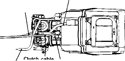 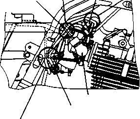
Washer
OIL PUMP (FROM X-MODEL) NOTE: Install the oil pump driven gear washer between the oil pump and its driven gear. XF650Y (2000-MODEL) This chapter describes service data, service specifications and servicing procedures which differ from those of the XF650X (’99-MODEL). NOTE: Any differences between XF650X (’99-MODEL) and XF650Y (2000-MODEL) in specifications and service data are clearly indicated with the asterisk marks (*). GROUP INDEX GENERAL INFORMATION ENGINE CHASSIS ELECTRICAL SYSTEM SERVICING INFORMATION GENERAL INFORMATION
SPECIFICATIONS 9-1-2 CONTENTS
4-stroke, Air-cooled, with SACS, OHC, Pent-roof 1 100 mm (3.937 in) 82 mm (3.228 in) 644 cm3 (39.3 cu. in) 9.5 : 1 MIKUNI BSR32SS, twin Polyurethane foam element Electric Wet sump 1 450 - 1 550 r/min....... E-18 1 400 - 1 600 r/min....... others SPECIFICATIONS DIMENSIONS AND DRY MASS Overall length.......................................... Overall width........................................... Overall height.......................................... Wheelbase.............................................. Ground clearance................................... Seat height.............................................. Dry mass................................................ ENGINE TVpe....................................................... Number of cylinders............................... Bore........................................................ Stroke..................................................... Displacement.......................................... Compression ratio................................... Carburetor............................................... Air cleaner............................................... Starter system........................................ Lubrication system.................................. Idle speed................................................ 2 190 mm (86.2 in)....... (Low seat) 865 mm (34.1 in) 1 240 mm (48.8 in) 1 210 mm (47.6 in)....... (Low seat) 1 465 mm (57.7 in) 1 455 mm (57.3 in)....... (Low seat) 200 mm (7.9 in) 170 mm (6.7 in)........ (Low seat) 830 mm (32.7 in) 800 mm (31.5 in)...... (Low seat) 168 kg (370 lbs)
TRANSMISSION Clutch.......................... Transmission............... Gearshift pattern......... Primary reduction ratio Final reduction ratio.... Gear ratios, Low......... 2nd.......... 3rd.......... 4th.......... 5th.......... Drive chain.................. Wet multi-plate type 5-speed constant mesh 1-down, 4-up 2.178 (61/28) 2.866 (43/15) 2.416 (29/12) 1.625 (26/16) 1.238 (26/21) 1.000 (21/21) 0.826 (19/23) D.I.D. 525 V8, 110 links CHASSIS Front suspension........................................................ Telescopic, coil spring, oil damped Rear suspension........................................................ Link type, coil spring, gas/oil damped, spring pre-load fully adjustable, compression damping force 16-way adjustable Front suspension stroke............................................. 170 mm (6.7 in) 140 mm (5.5 in)............ (Low seat) Rear wheel travel....................................................... 167 mm (6.6 in) 132 mm (5.2 in)............ (Low seat) Caster......................................................................... 28° Trail............................................................................ 105 mm (4.13 in) Steering angle............................................................ 43° (right & left) Turning radius............................................................ 2.4 m (7.9 ft) Front brake................................................................. Disk brake Rear brake................................................................. Disk brake Front tire..................................................................... 100/90-19 57H, tube type Rear tire..................................................................... 130/80R17 65H, tube type ELECTRICAL Ignition type................................................................ Electronic ignition (CDI) Ignition timing............................................................. 10° B.T.D.C. at 1 500 r/min Spark plug.................................................................. NGK CR10E or DENSO U31ESR-N Battery........................................................................ 12V 28.8 kC (8 Ah)/10 HR Generator................................................................... Three-phase A.C. generator Main fuse................................................................... 30 A Fuse........................................................................... Head-Hi 15/Head-Lo 15/lgnition 10/Signal 15/Tail 10 A Headlight.................................................................... * 12 V 60 + 55W/55W Position/parking light.................................................. 12V5W............................ Except E-24 Brake light/Taillight..................................................... 12V21/5W Turn signal light.......................................................... 12 V 21 W Speedometer light...................................................... 12V1.7Wx2 Turn signal indicator light........................................... 12 V 1.7 W x 2 Neutral indicator light................................................. 12 V 1.7W High beam indicator light........................................... 12 V 1.7 W CAPACITIES Fuel tank, including reserve....................................... 18.5 L (4.9/4.1 US/Imp gal) reserve..................................................... 4.5 L (1.2/1.0 US/Imp gal) Engine oil, oil change................................................. 2 300 ml (2.4/2.0 US/Imp qt) with filter change...................................... 2 400 ml (2.5/2.1 US/Imp qt) Front fork oil (each leg).............................................. 655 ml (22.1/23.1 US/Imp oz) 699 ml (23.6/24.6 US/Imp oz)....... (Low seat) ENGINE -------------------------- CONTENTS-------------------------- ENGINE REASSEMBLY................................................. 9-3-2 CLUTCH................................................................. 9-3-2 INSPECTION AND SERVICE........................................... 9-3-6 CLUTCH................................................................. 9-3-6 ENGINE REASSEMBLY CLUTCH For details other than the following, refer to the section 3.
© Clutch release arm ® Clutch release pinion ® Clutch release rack © Clutch pressure plate © Primary driven gear ass’y © Clutch sleeve hub ©Spring washer © No. 2 driven plate (1 pc, TH: 2.0 mm, 0.07 in) ® Stopper ring ® No. 1 drive plate (7 pcs) ® No. 1 driven plate (7 pcs, TH: 1.6 mm, 0.06 in) © No. 2 drive plate (1 pc) И 50 N-m (5.0 kgf-m, 36.0 Ib-ft) Install the thrust washer ©. NOTE: Check to be sure that the spring washer ® is properly installed. Щ 10 Nm (1.0 kgf-m, 7.0 Ib-ft)  
• • Install the thrust washer ©. NOTE: Apply engine oil to both the inside and outside of the spacer. • Install the clutch sleeve hub, lock washer (D, washer (D and clutch sleeve hub nut. NOTE: When installing the lock washer (D, align the slit ® of the lock washer with the rib of the clutch sleeb hub. A CAUTION _____________________________________ Pay attention to the direction of the lock washer and washer. [62] [63]
® No. 1 Drive Plate........... 7pcs (D No. 2 Drive Plate........... 1 pc DRIVEN PLATE ® No. 1 Driven Plate (Thickness): 1.6 mm (0.06 in)... 7pcs (© No. 2 Driven Plate (Thickness): 2.0 mm (0.07 in)... 1pc Install the No. 2 drive plate most outside. • Install the No. 1 drive plates and No. 1 driven plates (TH: 1.6 mm, 0.06 in) one by one. NOTE: The No. 1 and No. 2 drive plates can be distinguished by the plate surface. 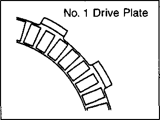  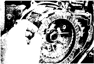 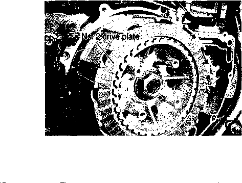
• Install the clutch springs and tighten the clutch spring bolts in a crisscross pattern, to the specified torque. И Clutch spring bolt: 10 N-m (1.0 kgf-m, 7.0 Ib-ft) • Face the rack teeth ® forward. • Install the two dowel pins and new gasket ©. • Apply engine oil to each gear, bearing and clutch plate. [64] INSPECTION AND SERVICE CLUTCH CLUTCH DRIVE PLATES Measure the thickness and claw width of the clutch drive plates using vernier calipers, if a clutch drive plate is not within the service limit, replace it with a new one. ШУ Thickness (No. 1 and No. 2) Service Limit: 2.6 mm (0.10 in) Claw width (No. 1 and No. 2) Service Limit: 14.8 mm (0.58 in) (ro^ 09900-20101: Vernier calipers CLUTCH DRIVEN PLATES Measure each clutch driven plate for distortion using the thickness gauge. If a clutch driven plate is not within the service limit, replace it with a new one. ШУ Clutch driven plate distortion Service Limit: 0.10 mm (0.004 in)
CHASSIS ------------------------- CONTENTS --------------------------- EXTERIOR PARTS..................................................... 9-5-2 CONSTRUCTION......................................................... 9-5-2 REMOVAL................................................................. 9-5-3 REMOUNTING............................................................ 9-5-5 EXTERIOR PARTS CONSTRUCTION
® Side fairing (L) ©Center fairing ® Speedometer panel ® Fairing upper bracket Ф Fairing brace ® Fuel tank cover (R) ® Fuel tank cover (L) ® Fuel tank upper cover ® Front frame cover (R) @ Front frame cover (L) ® Frame cover (R) ® Frame cover (L)
REMOVAL FAIRING • Remove the seat. • Remove the front frame covers (right and left).
• Remove the speedometer. • Disconnect the speedometer lead wire coupler. 
• Remove the screws. • Disconnect the turn signal light lead wire couplers (right and left). • Remove the fairing ass’y. • Disconnect the headlight sockets (D and remove the position light socket (D. [65]
• Remove the frame covers.  REMOUNTING Remount the frame covers and fairing in the reverse order of their removal. ELECTRICAL SYSTEM ------------------------- CONTENTS --------------------------- LAMPS....................................................................... 9-6-2 HEADLIGHT AND POSITION LIGHT................................. 9-6-2
• Remove the bulb ф by unlocking the bulb holder spring. LAMPS
BULB REPLACEMENT Headlight • Remove the speedometer. • Disconnect the speedometer lead wire coupler. • Disconnect the sockets. [66] Position light • • Pull off the socket ф. [67]
SERVICING INFORMATION ------------------------- CONTENTS ---------------------------- WIRING DIAGRAM..................................................... 9-7-2 WIRE, CABLE AND HOSE ROUTING............................... 9-7-3 WIRE ROUTING.......................................................... 9-7-3 FRONT BRAKE HOSE ROUTING..................................... 9-7-4 FAIRING SET-UP....................................................... 9-7-5
9-7 SERVICE DATA........................................................ 9-7-6 FRONT TURN SIGNAL LIGHT (R) 0r«TO=“*'
HANDLEBAR SWITCH (R} (For E24) ENGME STOP BRAKE STARTER SWITCH LIGHT SWfTCH BUTTON HANDLEBAR SWITCH (R) FRONT LIGHTING -jENGINE STOP BRAKE STARTER SWITCH HEAD UGHT(LO THROTTLE SOLENOID POSITION SENSOR -B/W- POSmON LIGHT (Except lor E24) FRONT TURN SIGNAL UGHT (L) REAR TURN SIGNAL LIGHT (R) BRAKE LJGHTrtAILUGHT REAR TURN SIGNAL LIGHT (L) ."=0К!Л§) WIRE COLORS в........ ••• Black Bl....... • • • Blue Br • • • • • • • Brown G........ • • • Green Gr • • • Gray Lbl----- • ■ • Light blue Lfl------ • ■ • Light green o.... • • • Orange P....... • • Pink R........ • • • Red w....... •White v........ • • • Yellow B®l. • • • Black with Blue tracer B/G • • • Black with Green tracer B/Lg •• • • • Black with Light green tracer B/O • • • • ■ • Black with Orange tracer B/R • • • • • ■ Black with Red tracer в/w... • • • Black with White tracer Вn... • • ■ Black with Yellow tracer вге ■ • • Blue with Black tracer G/R • • • • • • Green with Red tracer Gr® • • • • • Gray with Black tracer 0® • • • Orange with Black tracer O/BJ • • • Orange with Blue tracer ОЛЗ • • • Orange with Green tracer om • • • Orange with Red tracer от- • • • Orange with White tracer on • • • Orange with Yellow tracer R/B • • • • • • Red with Black tracer W®- • • • White with Black tracer W/BI •• ■ • ■ White with Blue tracer Y® ••• • • • Yellow with Black tracer Y/Q... • • • Yellow with Green tracer Y/W • • • • • • Yellow with White tracer
BUTTON TURN SIGNAL SWITCH HANDLEBAR SWITCH (L) GENERATOR HEAD UGHTfHI) TL TR NU HI ШИ TURN SIGNAL INDICATOR LIGHT (L) TURN SIGNAL INDICATOR LIGHT (R) NEUTRAL INDICATOR LIGHT HIGH BEAU INDICATOR LIGHT METER UUMINATON   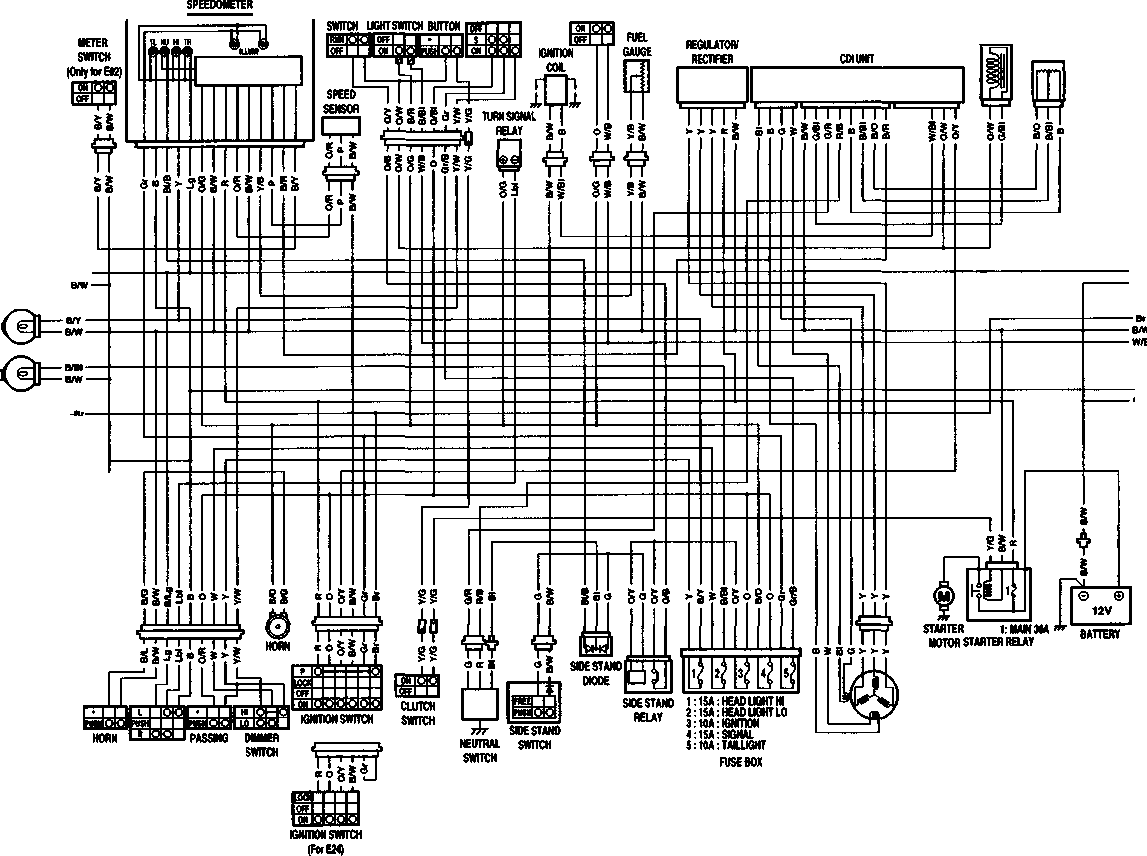
WIRE, CABLE AND HOSE ROUTING WIRE ROUTING
Clamp Wiring harness Headlight ass’y Fairing brace  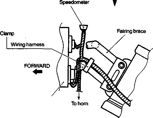
FRONT BRAKE HOSE ROUTING
^— Pass the brake hose and throttle cables through the guide. After touching the brake hose union to the stopper, tighten the union bolt to the specified torque. Brake hose union bolt Washer Throttle cables (Q 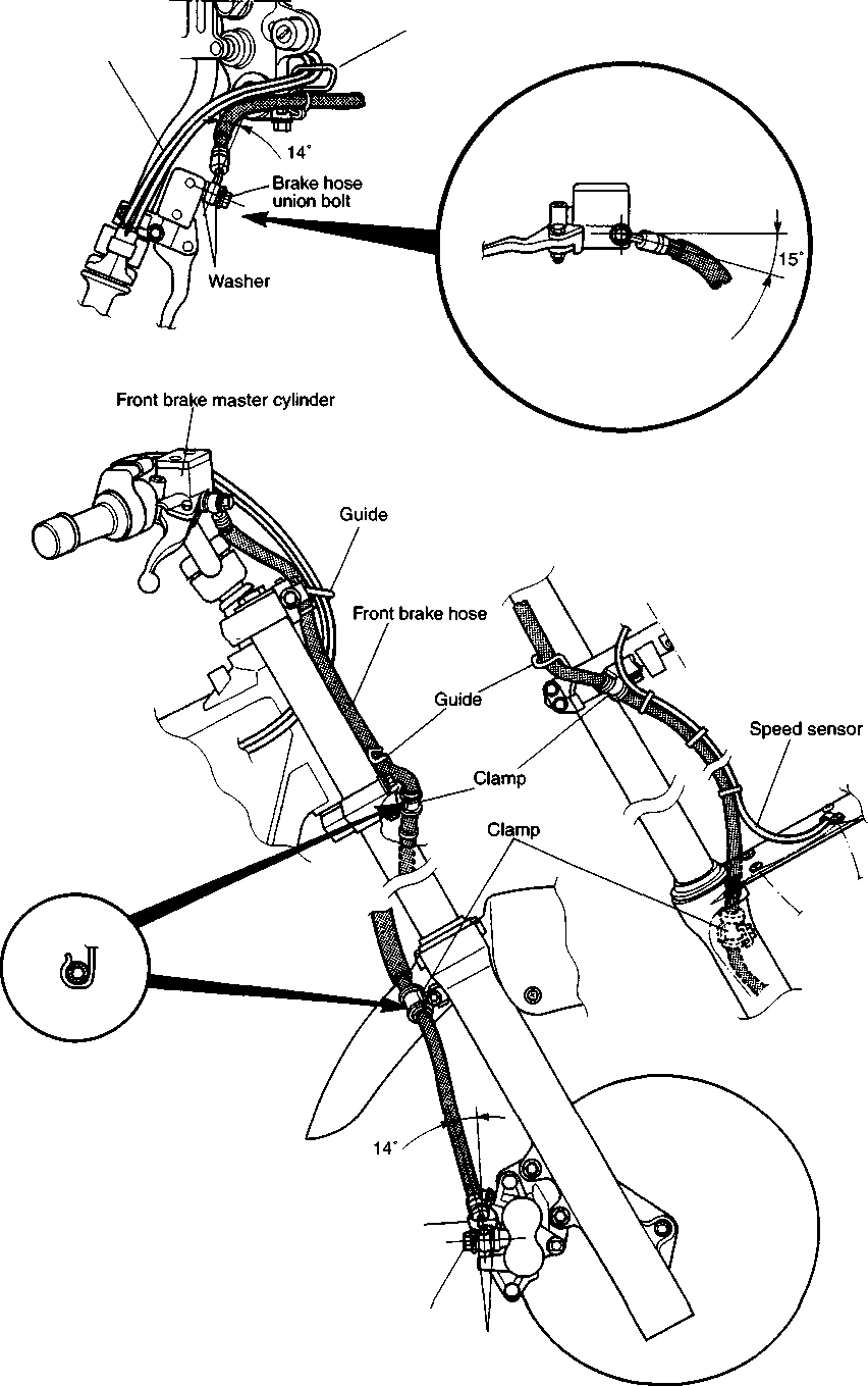
/ Protector
Fairing brace /    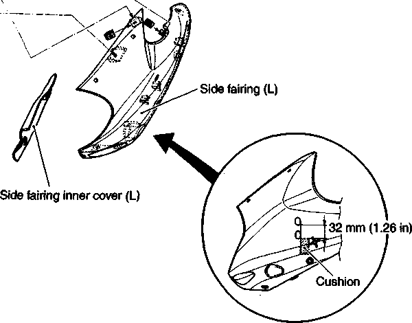  
SERVICE DATA VALVE + GUIDE ___________ ITEM Valve diam. EX. IN. Valve guide to valve stem clearance EX. Unit: mm (in) LIMIT Valve stem deflection Valve guide I.D. Valve stem O.D. EX. Valve stem runout Valve stem end length Valve head radial runout Valve spring tension (IN. & EX.) INNER INNER 0.05 (0.002) 0.5 (0.02) 2.7 (0.11) 0.03 (0.001) 34.4 (1-35) 38.1 (1.50) 5.9 - 6.7 kgf 13.8 - 15.8 kgf 0.9 - 1.1 OUTER OUTER IN. & EX. IN. & EX. IN. & EX. IN. & EX. IN. & EX. Valve spring free length (IN. & EX.)У Valve seat width Valve head thickness 5.500 - 5.512 (0.2165 - 0.2170) 5.475 - 5.490 (0.2156 - 0.2161) 5.455 - 5.470 (0.2148 - 0.2154) IN. & EX. IN. & EX. IN. 0.35 (0.014) STANDARD (1-4) (1-2) 0.08 - 0.13 0.17-0.22 0.010 - 0.037 (0.0004 - 0.0015) 0.030 - 0.057 (0.0012 - 0.0022) IN. EX. Valve clearance (when engine is cold) IN.
CAMSHAFT + CYLINDER HEAD Unit: mm (in) ITEM STANDARD LIMIT Cam height IN. 33.690 - 33.758 (1.3264 - 1.3291) 33.390 (1.3146) EX. 33.680 - 33.748 (1.3260 - 1.3287) 33.380 (1.3142) Camshaft journal oil clearance Right & Center 0.032 - 0.066 (0.0013 - 0.0026) 0.150 (0.0059) Left 0.028 - 0.059 (0.0011 - 0.0023) 0.150 (0.0059) Camshaft journal holder I.D. Right & Center 22.012 - 22.025 (0.8666 - 0.8671)
Left 17.512 - 17.525 (0.6894 - 0.6900)
Camshaft journal O.D. Right & Center 21.959 - 21.988 (0.8645 - 0.8657)
Left 17.466 - 17.492 (0.6877 - 0.6887)
Camshaft runout
0.10 (0.004) Rocker arm I.D. IN. & EX. 12.000 - 12.018 (0.4724 - 0.4731)
Rocker arm shaft O.D. IN. & EX. 11.973 - 11.984 (0.4714 - 0.4718)
Cylinder head distortion
0.05 (0.002) Cylinder head cover distortion
0.05 (0.002)
CYLINDER + PISTON + PISTON RING Unit: mm (in) ITEM STANDARD LIMIT Piston to cylinder clearance 0.020 - 0.030 (0.0008 - 0.0012) 0.120 (0.0047) Cylinder bore 100.000 - 100.015 (3.937 - 3.9376) Nicks or Scratches Piston diam. 99.975 - 99.990 (3.9360 - 3.9366) Measure at 21 mm (0.8 in) from the skirt end. 99.880 (3.9323) Cylinder distortion
0.05 (0.002) Piston ring free end gap 1st R ApProx(0353) 10.8 (0.43)
2nd R л 11.4 Approx.(o 45) 9.1 (0.36) Piston ring end gap 1st 0.30 - 0.45 (0.012 - 0.018) 0.50 (0.020)
2nd 0.45 - 0.60 (0.018 - 0.024) 1.00 (0.039) Compression pressure (Automatic decomp, actuated) 850 kPa Approx. ( 8.5 kgf/cm2 \ \ 120 psi /
ITEM STANDARD LIMIT Piston ring to groove clearance 1st
0.180 (0.0071)
2nd
0.150 (0.0059) Piston ring groove width 1st 1.230 - 1.250 (0.048 - 0.049)
2nd 1.210 - 1.230 (0.047 - 0.048)
Oil 2.810 - 2.830 (0.110 - 0.111)
Piston ring thickness 1st 1.170 - 1.190 (0.0461 - 0.0469)
2nd 1.150 - 1.170 (0.0453 - 0.0461)
Piston pin bore 23.002 - 23.008 (0.9056 - 0.9058) 23.030 (0.9067) Piston pin O.D. 22.992 - 23.000 (0.9052 - 0.9055) 22.980 (0.9047)
CONROD + CRANKSHAFT Unit: mm (in) ITEM STANDARD LIMIT Conrod small end I.D. 23.017 - 23.025 23.040
(0.9062 - 0.9065) (0.9071) Conrod deflection
3.0 (0.12) Conrod big end side clearance 0.10 - 0.65 1.00 (0.004 - 0.026) (0.039) Conrod big end width 24.95 - 25.00 (0.982 - 0.984)
Crankshaft runout
0.08 (0.003) Crank web to web width 71.0 ± 0.1 (2.795 ± 0.004)
OIL PUMP ITEM STANDARD LIMIT Oil pump reduction ratio 1.633 (61/28 x 30/20 x 15/30)
Oil pressure (at 60°C,140°F) Above 30 kPa (0.3 kgf/cm2, 4.3 psi) Below 70 kPa (0.7 kgf/cm2, 10.0 psi) at 3 000 r/min
CLUTCH Unit: mm (in) ITEM STANDARD LIMIT Clutch lever play 10 - 15 (0.4 - 0.6)
Drive plate thickness No.1 & 2.9 - 3.1 2.6 No.2 (0.11 - 0.12) (0.10) Driven plate distortion
0.10 (0.004) Clutch spring free length
33.0 (1.30) Unit: mm (in) Except ratio
TRANSMISSION + DRIVE CHAIN Drive chain slack STANDARD 2.178 (61/28) 2.866 (43/15) 2.416 (29/12) 1.625 (26/16) 1.238 (26/21) 1.000 (21/21) 0.826 (19/23) 0.10 - 0.30 LIMIT (0.004 - 0.012) (0.197 - 0.200) 0.50 (0.020) 4.8 - 4.9 Type * DAIDO:DID525V8
Links
20-pitch length
319.4 (12.57)
20 - 30 (0.8 - 1.2) ITEM Primary reduction ratio Final reduction ratio Gear ratios Low 2nd 3rd 4th ____________________ Top Shift fork to groove clearance Shift fork groove width Shift fork thickness Drive chain
CARBURETOR ITEM SPECIFICATION E-02, 04, 17, 22, 24, 25, 34, P-09 E-18 Carburetor type MIKUNI BSR32SS <r- Bore size 32 mm <r- I.D. No. 04 F0 04F1 Idle r/min. 1 500 ± 100 r/min. 1 500 ± 50 r/min. Float height 13.0 ± 1.0 mm (0.51 ± 0.04 in) <r- Main jet (M.J.) #115 <r- Jet needle (J.N.) 5DH23-53-3rd <r- Needle jet (N.J.) P-0 <r- Throttle valve (Th.V.) #90 <r- Pilot jet (P.J.) #20 <r- Pilot screw (PS.) PRE-SET (3 turns back) <r- Throttle cable play (pulling cable) 0.5 - 1.0 mm (0.02 - 0.04 in) <r- Starter cable play 0.5 - 1.0 mm (0.02 - 0.04 in) <r-
CARBURETOR ITEM SPECIFICATION U-type E-22 P-37 Carburetor type MIKUNI BSR32SS <r- Bore size 32 mm <r- I.D. No. 04F3 04F4 Idle r/min. 1 500 ± 100 r/min. <r- Float height 13.0 ± 1.0 mm (0.51 ± 0.04 in) <r- Main jet (M.J.) #115 #122.5 Jet needle (J.N.) 5DH23-53-3rd 5DH34-53-3rd Needle jet (N.J.) P-0 <r- Throttle valve(Th.V.) #90 <r- Pilot jet (P.J.) #20 #22.5 Pilot screw (P.S.) PRE-SET (3 turns back) PRE-SET (3% turns back) Throttle cable play (pulling cable) 0.5 - 1.0 mm (0.02 - 0.04 in) <r- Starter cable play 0.5 - 1.0 mm (0.02 - 0.04 in) <r-
ELECTRICAL Unit: mm (in) ITEM SPECIFICATION NOTE Ignition timing 10° B.T.D.C at 1 500 r/min.
Spark plug Type DENSO: U31ESR-N N.G.K.: CR10E
Gap 0.7 - 0.8 (0.028 - 0.031)
Spark performance Over 8 (0.3) at 1 atm.
Ignition coil resistance Primary 0.07 - 0.12 П B-B/W Secondary 23 - 25 kQ Plug cap - Plug cap Generator coil resistance Charging 0.5 - 0.9 П Y-Y Power source 0.1 - 0.2 П B-W Pick-up 170 - 256 П Bl-G Generator no-load voltage More than 75 V(AC) at 5 000 r/min.
Generator Max. output Approx. 200W at 5000 r/min.
Regulated voltage 13.0 - 16.0 V at 5 000 r/min.
Starter relay resistance 3-50
Battery Type designation YTX9-BS
Capacity 12V 28.8 kC (8Ah)/10 HR
Standard electrolyte S.G. 1.320 at 20°C (68°F)
Fuse size Main 30 A
Headlight (H) 15 A
Headlight (L) 15 A
Ignition 10 A
Signal 15 A
Tail 10 A
WATTAGE Unit:W ITEM SPECIFICATION E-24 The others Headlight HI *60 + 55 . ..'I; LO +- Parking or position light _______ ———-------- ' Brake lilght/Taillight 21/5 +- Turn signal light +- Speedometer light 1.7 x 2 +- Turn signal indicator light 1.7 x 2 +- High beam indicator light 1.7 +- Neutral indicator light 1.7 +-
BRAKE + WHEEL ___________ ITEM Rear brake pedal height Front STANDARD______ (0-2)_____________ 4.5 ± 0.2 (0.177 ± 0.008) 4.5 ± 0.2 (0.177 ± 0.008) Brake disc runout Master cylinder bore Rear Front Brake caliper cylinder bore Rear Front 12.700 - 12.743 (0.5000 - 0.5017) 14.000 - 14.043 (0.5511 - 0.5528) 12.657 - 12.684 (0.4983 - 0.4994) 13.957 - 13.984 (0.5494 - 0,5505) 30.230 - 30.306 (1.1902 - 1.1931) 38.18 - 38.23 (1.503 - 1.505) 30.15 - 30.20 (1.187 - 1.189) 38.08 - 38.13 (1.499 - 1.501) Axial Wheel axle runout Tire rim size Rear Front Rear Front Rear J19 x MT2.50 Front 3.0 3.0 Rear Tire tread depth 2.0 (0.08) 2.0 (0.08) 0.25 (0.010) 0.25 (0.010) Tire size Front Radial Wheel rim runout Rear Brake caliper piston diam. Front Rear Master cylinder piston diam. Front 4.0 4.0 0.30 LIMIT Rear Brake disc thickness Unit: mm (in)
SUSPENSION Unit: mm (in) ITEM STANDARD LIMIT NOTE Front fork stroke (6.7)
(5.5)
Low seat Front fork spring free length
(14.6)
Front fork oil level (5.6)
(3.6)
Low seat Rear shock absorber spring pre-set length 169.2 (6.7)
Rear wheel travel (6.6)
(5.2)
Low seat Swingarm pivot shaft runout
0.3 (0.01)
TIRE PRESSURE COLD INFLATION TIRE PRESSURE SOLO RIDI NG DU AL RID NG kPa kgf/cm2 psi kPa kgf/cm2 psi FRONT 1.75 1.75 REAR 2.00 2.25
FUEL + OIL ITEM SPECIFICATION NOTE Fuel type Gasoline used should be graded 85-95 octane or higher. An unleaded gasoline is recommended.
Fuel tank including 18.5 L (4.9/4.1 US/Imp gal)
reserve 4.5 L (1.2/1.0 US/Imp gal)
Engine oil type SAE 10W/40, API SF or SG
Engine oil capacity Change 2 300 ml (2.4/2.0 US/Imp qt)
Filter change 2 400 ml (2.5/2.1 US/Imp qt)
Overhaul 2 600 ml (2.7/2.3 US/Imp qt)
Front fork oil type Fork oil #15
Front fork oil capacity (each leg) 655 ml (22.1/23.1 US/Imp oz)
699 ml (23.6/24.6 US/Imp oz) Low seat Brake fluid type DOT 4
XF650K1 (’01-MODEL) --------------------------- CONTENTS---------------------------- SPECIFICATIONS.......................................................... 10- 1 SERVICE DATA............................................................ 10- 2 NOTE: The specifications and service data are the same as the Y-model. SPECIFICATIONS Overall length................................. .............................. 2 mm (86.8 in)
mm (86.2 in) .. ... (Low seat) Overall width..................................
mm (34.1 in)
Overall height................................. .............................. 1 mm (48.8 in)
mm (47.6 in) .. ... (Low seat) Wheelbase....................................... ............................... 1 mm (57.7 in)
mm (57.3 in) ... ... (Low seat) DIMENSIONS AND DRY MASS Ground clearance........................................................... 200 mm (7.9 in) 170 mm (6.7 in)..... (Low seat) Seat height...................................................................... 830 mm (32.7 in) 800 mm (31.5 in)..... (Low seat) Dry mass......................................................................... 168 kg (370 lbs)
4- ENGINE Type.............................. Number of cylinders.... Bore.............................. Stroke........................... Displacement.............. Compression ratio..... Carburetor.................... Air cleaner.................... Starter system............ Lubrication system.... Idle speed.................... TRANSMISSION Clutch........................... Transmission............... Gearshift pattern......... Primary reduction ratio Final reduction ratio .... Gear ratios, Low......... 2nd.......... 3rd........... 4th........... 5th........... Drive chain................... CHASSIS Front suspension................. Rear suspension................... Front suspension stroke..... Rear wheel travel.................. Caster..................................... Trail......................................... Steering angle....................... Turning radius...................... Front brake............................ Rear brake.............................. Front tire................................ Rear tire................................. ELECTRICAL Ignition type.......................... Ignition timing...................... Spark plug............................. Battery.................................... Generator............................... Main fuse............................... Fuse........................................ Headlight............................... Position/parking light.......... Brake light/Taillight.............. Turn signal light................... Speedometer light................ Turn signal indicator light... Neutral indicator light.......... High beam indicator light.... CAPACITIES Fuel tank, including reserve.. reserve.................. Engine oil, oil change.......... with filter change Front fork oil (each leg).......................................... stroke, Air-cooled, OHC 1100 mm (3.937 in) 82 mm (3.228 in) 644 cm3 (39.3 cu. in) 9.5:1 MIKUNI BSR32SS, twin Polyurethane foam element Electric Wet sump 1 450-1 550 r/min...... E-18 1 400 - 1 600 r/min...... others Wet multi-plate type 5- speed constant mesh 1-down, 4-up 2.178 (61/28) 2.866 (43/15) 2.416 (29/12) 1.625 (26/16) 1.238 (26/21) 1.000 (21/21) 0.826 (19/23) D.I.D. 525 V8, 110 links Telescopic, coil spring, oil damped Link type, coil spring, oil damped, spring pre-load fully adjustable, compression damping force 16-way adjustable 170 mm (6.7 in) 140 mm (5.5 in)..... (Low seat) 167 mm (6.6 in) 132 mm (5.2 in)..... (Low seat) 28° 105 mm (4.13 in) 43° (right & left) 2.4 m (7.9 ft) Disk brake Disk brake 100/90-19 57H, tube type 130/80R17 65H, tube type Electronic ignition (CDI) 10° B.T.D.C. at 1 500 r/min NGK CR10E or DENSO U31ESR-N 12V 28.8 kC (8 Ah)/10HR Three-phase A.C. generator 30A Head-Hi 15/Head-Lo 15/lgnition 10/Signal 15/Tail 10A 12V 60 + 55W/55W 12V 5W...... Except E-24 12V 21/5W 12V 21W 12V 1.7W x 2 12V 1.7W x 2 12V 1.7W 12V 1.7W 18.5 L (4.9/4.1 US/Imp gal) 4.5 L (1.2/1.0 US/Imp gal) 2 300 ml (2.4/2.0 US/Imp qt) 2 400 ml (2.5/2.1 US/Imp qt) 655 ml (22.1/23.1 US/Imp oz) 699 ml (23.6/24.6 US/Imp oz)..... (Low seat)
SERVICE DATA VALVE + GUIDE Unit: mm ___________ ITEM Valve diam. Valve clearance (When engine is cold) Valve guide to valve stem clearance Valve stem deflection Valve guide I.D. Valve stem O.D. Valve stem runout Valve head thickness Valve stem end length Valve seat width Valve head radial runout Valve spring free length (IN. & EX.) Valve spring tension (IN. & EX.) IN. EX. IN. EX. IN. EX. IN. & EX. IN. & EX. IN. & EX. IN. & EX. IN. & EX. IN. & EX. INNER OUTER INNER STANDARD ________ 30 0.08-0.13 0.17-0.22 0.010-0.037 0.030 - 0.057 5.500-5.512 5.475 - 5.490 5.455 - 5.470 0.9- 1.1 LIMIT 0.35 0.05 0.5 2.7 0.03 34.4 38.1 OUTER 5.9 - 6.7 kgf 13.8-15.8 kgf CAMSHAFT + CYLINDER HEAD Unit: mm ITEM STANDARD LIMIT Cam height IN. 33.690 - 33.758 33.390 EX. 33.680 - 33.748 33.380 Camshaft journal oil clearance Right & Center 0.032 - 0.066 0.150 Left 0.028 - 0.059 0.150 Camshaft journal holder I.D. Right & Center 22.012-22.025
Left 17.512- 17.525
Camshaft journal O.D. Right & Center 21.959 - 21.988
Left 17.466 - 17.492
Camshaft runout
0.10 Rocker arm I.D. IN. & EX. 12.000- 12.018
Rocker arm shaft O.D. IN. & EX. 11.973 - 11.984
Cylinder head distortion
0.05 Cylinder head cover distortion
0.05
CYLINDER + PISTON + PISTON RING Unit: mm ITEM STANDARD LIMIT Piston to cylinder clearance 0.020 - 0.030 0.120 Cylinder bore 100.000 - 100.015 Nicks or Scratches Piston diam. 99.975 - 99.990 Measure at 21 mm from the skirt end. 99.880 (3.9323) Cylinder distortion
0.05 Piston ring free end gap 1st R Approx. 13.5 10.8 2nd R Approx. 11.4 9.1 Piston ring end gap 1st 0.30 - 0.45 0.50 2nd 0.45 - 0.60 1.00 Compression pressure (Automatic decomp, actuated) * nrnv 850 kPa Approx. (8 5 kgf/cm2)
Piston ring to groove clearance 1st
0.180 2nd
0.150 Piston ring groove width 1st 1.230 - 1.250
2nd 1.210 - 1.230
Oil 2.810-2.830
Piston ring thickness 1st 1.170 - 1.190
2nd 1.150 - 1.170
Piston pin bore 23.002 - 23.008 23.030 Piston pin O.D. 22.992 - 23.000 22.980
CONROD + CRANKSHAFT Unit: mm ITEM STANDARD LIMIT Conrad small end I.D. 23.017-23.025 23.040 Conrad deflection
3.0 Conrad big end side clearance 0.10-0.65 1.00 Conrad big end width 24.95 - 25.00
Crankshaft runout
0.08 Crank web to web width 71.0 ± 0.1
OIL PUMP ITEM STANDARD LIMIT Oil pump reduction ratio 1.633 (61/28 x 30/20 x 15/30)
Oil pressure (at 60°C,140°F) Above 30 kPa (0.3 kgf/cm2) Below 70 kPa (0.7 kgf/cm2) at 3 000 r/min
CLUTCH Unit: mm ITEM STANDARD LIMIT Clutch lever play 10-15
Drive plate thickness No. 1 & p q q -| No.2 2.6 Driven plate distortion
0.10 Clutch spring free length
33.0 Unit: mm Except ratio
TRANSMISSION + DRIVE CHAIN ITEM STANDARD LIMIT Final reduction ratio Gear ratios 2nd 3rd Top Shift fork to groove clearance Shift fork groove width Type 2.178 (61/28) 2.416 (29/12) 0.826 (19/23) 0.10-0.30 5.0-5.1 4.8-4.9 0.50 Drive chain slack CARBURETOR ITEM SPECIFICATION E-02, 04, 17, 22, 24, 34 E-18 Carburetor type MIKUNI BSR32SS <r- Bore size 32 mm <r- I.D. No. 04F0 04F1 Idle r/min. 1 500 ±100 r/min. 1 500 ± 50 r/min. Float height 13.0 ±1.0 mm
Main jet (M.J.) #115 <r- Jet needle (J.N.) 5DH23-53-3rd <r- Needle jet (N.J.) P-0 <r- Throttle valve (Th.V.) #90 <r- Pilot jet (P.J.) #20 <r- Pilot screw (PS.) PRE-SET (3 turns back) <r- Throttle cable play 2.0 - 4.0 mm <r- Starter cable play 0.5 -1.0 mm <r-
20-30 319.4 DAIDO.DID525V8 1.625 (26/16) 1.238 (26/21) 1.000 (21/21) 2.866 (43/15) Links 20-pitch length Shift fork thickness Drive chain 4th Low Primary reduction ratio
CARBURETOR ITEM SPECIFICATION U-type E-22 Carburetor type MIKUNI BSR32SS Bore size 32 mm I.D. No. 04F3 Idle r/min. 1 500 ± 100 r/min. Float height 13.0 ±1.0 mm Main jet (M.J.) #115 Jet needle (J.N.) 5DH23-53-3rd Needle jet (N.J.) P-0 Throttle valve (Th.V.) #90 Pilot jet (P.J.) #20 Pilot screw (P.S.) PRE-SET (3 turns back) Throttle cable play 2.0-4.0 mm Starter cable play 0.5 - 1.0 mm
ELECTRICAL ITEM SPECIFICATION NOTE Spark plug Type DENSO: U31ESR-N NGK: CR10E
Gap 0.7 - 0.8 mm
Spark performance Over 8 mm at 1 atm.
Ignition coil resistance Primary 0.07-0.12 Q B-B/W Secondary 23 - 25 Ш Plug cap - Plug cap Generator coil resistance Charging 0.5 - 0.9 Q Y-Y Power source 0.1 -0.2Й B-W Pick-up 170-256 Q Bl-G Generator no-load voltage More than 75 V(AC) at 5 000 r/min.
Generator Max. output Approx. 200 W at 5 000 r/min.
Regulated voltage 13.0-16.0 Vat 5 000 r/min.
Starter relay resistance 3-5 Q
Battery Type designation YTX9-BS
Capacity 12V 28.8 kC (8Ah)/10 HR
Standard electrolyte S.G. 1.320 at 20°C (68° F)
Fuse size Main 30 A
Headlight (H) 15 A
Headlight (L) 15 A
Ignition 10 A
Signal 15 A
Tail 10 A
WATTAGE unit:W ITEM SPECIF CATION E-24 The others Headlight HI 60 + 55 <r- LO <r- Parking or position light —---------- ‘ Brake lilght/Taillight 21/5 <r- Turn signal light <r- Speedometer light 1.7x2 <r- Turn signal indicator light 1.7x2 <r- High beam indicator light 1.7 <r- Neutral indicator light 1.7 <r- Unit: mm
BRAKE + WHEEL ___________ ITEM Rear brake pedal height Brake disc thickness Front Rear STANDARD 4.5 ±02 4.5 ± 0.2 LIMIT Brake disc runout Master cylinder bore 4.0 4.0 0.30 Master cylinder piston diam. Brake caliper cylinder bore Brake caliper piston diam. Wheel rim runout Wheel axle runout Tire rim size Tire size Tire tread depth Front Rear Front Rear Front Rear Front Rear Axial Radial Front Rear Front Rear Front Rear Front Rear 12.700- 12.743 14.000 - 14.043 12.657- 12.684 13.957- 13.984 30.230 - 30.306 38.18-38.23 30.15-30.20 38.08-38.13 J19 x MT2.50 2.0 2.0 0.25 0.25 3.0 3.0
SUSPENSION Unit: mm ITEM STANDARD LIMIT NOTE Front fork stroke
Low seat Front fork spring free length
Front fork oil level
Low seat Rear shock absorber spring pre-set length 169.2
Rear wheel travel
Low seat Swingarm pivot shaft runout
0.3
TIRE PRESSURE COLD INFLATION TIRE PRESSURE SOLO RIDING DUAL RIDING kPa kgf/cm2 kPa kgf/cm2 FRONT 1.75 1.75 REAR 2.00 2.25
FUEL + OIL ITEM SPECIFICATION NOTE Fuel type Gasoline used should be graded 91 octane or higher. An unleaded gasoline is recommended.
Fuel tank including reserve 18.5 L
reserve 4.5 L
Engine oil type SAE 10W/40, API SF or SG
Engine oil capacity Change 2 300 ml
Filter change 2 400 ml
Overhaul 2 600 ml
Front fork oil type Fork oil #15
Front fork oil capacity (each leg) 655 ml
699 ml Low seat Brake fluid type DOT 4
+ LONG TERN TEST
CCMR30 Ш НЕМ it comes to suspension :set-up everyone's an expert. Except in reality almost That's why I took my CCM R30 long term test biketo a REAtf;:!; expert to extract the best from the bike's . top-grade WP mofocross suspension. ' r Wayne Lamb knows his.stuff about supermotos like the R30 - he raced in the British supermoto series in the late '80s and took the British title in 1989 on a snarling Kawasaki KX500. ' r He currently fettles the.suspension of - road racers and motocrossers throughout the UK including many of the top .supersport championship racers. . The result of a morning's work with ' Lamb is a more balanced, more fun, better • handling machine that now has the ideal settings for the road use that accounts' for most of my time on the R30, The areas I needed to improve were: о Bump absorption '.«; Front end patter and response. Ф . Fork dive under braking All three are better than before thanks to Lamb's efforts. The settings were' arrived at . Heavier riders will typically need more : preload and compression damping and -.. ; less rebound damping; lighter riders vice . • versa'. Bear in mind, though, that no two bikes are identical. So if you are in any 'doubt about making changes, get an . ■ • ■ expert to check them out ' T .’• : From my perspective the changes nave ' revolutionised the handling. It's hard to be ' super-analytic about which changes have; , • changed what, not least because the' ' settings we started with were a non-'?V-v v standard mish-mash that had been the end result of lending the bike out to . various friends and work colleagues, each ' of whom had fiddled with at least one ; adjuster at some point • But what I can say is that with the . : settings shown below, the skittish front end is now much more firmly planted and the . rear end doesn't react to bumps as viciously. You can go faster on open roads : and have more control around town. , The round trip to Lamb's place in hanby in Lincolnshire was much more than an • While the suspension tune-up has undoubtedlyimprovedthe ride,It was never going to turn the R30 into some kind of long-haul hack. . '' I left my home in Kettering at just after 8am, took as many twisty, routes as I could, spent hours working with. Lamb on .the set-up arid then rode back to the office in Peterborough and finally back to Kettering in the evening. Sore is not really a big.enough word to describe how I felt after 233 miles of the narrow seat trying its hardest to cut me in half. Clearly this is not the sort of journey .that many R30.owners will attempt - and if. you take my advice you'll NEVER try it. ' unless you enjoy self-flagellation. Apart from the silliness of the long trip, life with the R30 is still good fun.l try to use it every day for the back-road run to work, and fitting a set of super sticky Pirelli Dra^n Super Corsas in place of the i :.r- v original Dragon Evos has given me a lot more faith in the grip of the bike. .1 had to get rid of the Evos after an office full of fools kept skidding.the bike around the place and left the rear bald and scorched. The new tyres have only just become . available in the bike’s unusual 150/60 rear' .tyre size but they suit the R30 really well: They have a noticeably different profile to the old tyres. No matter how hard I try, I cannot get them over the edges - even when the pegs are.scraping on the floor. there is still a virginal l'cm strip left untouched. 'With the bike's mileage now at almost 2000 miles, I've felt the engine starting to go off tune ever so slightly; though on the . plus side, the oil consumption rate has . ■slowed. You still need to keep a close eye on the sight glass as this is a motor that has to be constantly tnrashed 'up near the rev limiter'to make any kind of progress. 1 With the summer over, my next plan is getting the CCM ready for winter. It’s a bike that should be rideable alLyear round, and; it looks like it should stand up to the salt . and grime assault - but: need to. give it ;L. every chance of surviving intact © Wayne Lamb is on 01507-327509.
FRONT SET-UP
BRINGING the forks up through the yokes improves steering response but can decrease stability. Any decrease on my R30 seems to have been more than compensated for by one of the other adjustments. With the bike on a stand, undo the bolts clamping the forks and move them a lip up so the distance H between the top of ;*^t:7thetbp yokeandthe . W • aluminium top cap : • Utt. of the forks is set CCM R3G SUPERMOTO Rider* v.>Т-. ’.".T . Andy Downes Previously owned Yamaha Fazer 600 (twice), ; Suzuki SV6505. Triumph TT600, Ducati 996, CBR600F4 race bike (stili own) Date acquired ;;: % •v- Viay 22, 2002 ■ Priceiк■:■■ x, List price new: £5250 Value now: £4375 Pirelli Dragon Evo: Very sticky, heat up quicxiy and .suit the b,-ke wet or dry Pirefli Dragon Super Corsa: . Stupidly grippy, still stable .although wet grip with tlie semi-, slick tread pattern could be iffy Fun, individuality, looks, handling and smooth Suzuki motor Fuel range, oil consumption „Best moment g Riding home after having the suspension sorted Realising I still had another 100 . miles'to go before I got home Type of riding ... ,: Hacking around country lanes, tacking town and frequent commutes AccesSpries/costs .Qiain wax • •’ £5.99 Commuter tank : £150 Total £155.99
FRONT REBOUND: Turn the knob on top of each fork fully in then bring it back four clicks instead of the standard 14. The rule of thumb is clockwise for harder, anti-clockwise softer. THE first thing we sorted out , | on the bike was the sag. This is the distance the rear of the Т.Д- шй bike sinks when you sit on it. : •! Get a tape measure and find Щт a fixed point on the rear of tire bike. Measure the 1 distance from that point to 4 § ^ « the middle of ttie rear wheel ! • spindle. Now sit with your full weight on the bike (eg no feet isfc,1 Ш down) and get someone to measure the same distance. j • The difference between the ' !1ЯННнНЯЯВВВНВШнВнНЩВЯН9ВЯвВн1 measurements should be SHOCK rebound is adjusted using collar at lower end around 50mm, for this bike | and my type of usage. If it's not then the sag can be adjusted using the doubie metal collar on the top of the shock, which alters the preload. REAR REBOUND: The rebound is adjusted using the collar at the bottom of the shock. We found position seven (the ring is numbered), which is one up on standard, was ideal for a rider of my weight. ■ REAR COMPRESSION: This adjuster is a bitch to get to as it's hidden at the top of the shock next to the engine (and it gets very hot). Wind in the Ыаск plastic adjuster all the way clockwise and then bring it back three clicks (stock is seven clicks out). at 12mm on both legs. Take care not to overtighten the pinch bolts as this can damage the forks. Standard is Omm. FORKS now protrude by 12mm THAT'S the ride and handling sorted - now the CCM has to be readied for winter FRONT COMPRESSION: Found at the bottom of each leg under a bung. Remove the bung and dial in the adjuster with a screwdriver to maximum - then come back 15 clicks (stock is 14 clicks out).
R30 Harness  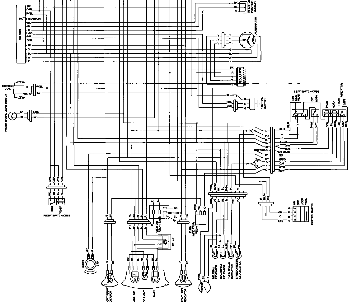
Table of contents English Dcutsch I Francis I Italy I
Shock Absorber manual •introduction 16 • set-up and adjustment 17 • periodic maintenance 20 • workshop -spring- 21 • workshop -removing the oil- 22 • workshop -spindle- 23 • workshop -refilling the oil- 26 • workshop -bleeding the air- 25 • workshop -assembly- 26 • troubleshooting 27 • importers 28 Introduction Congratulations on the purchase of one of the world's best motocross shock absorbers. World champions in almost every class of motor sport have preceded you in buying shock absorbers by WP Suspension. Just like all WP Suspension products, your shock absorber was designed in accordance with state of the art' technology in cooperation with the most demanding professional racing drivers. It was tested under the most extreme circumstances. The result? Greater comfort, greater safety and above all: the best performance. WP Suspension has more than twenty years experience in the development of suspension systems for motocross. road racing and Formula 1. Our products have been very successful and have been used by world champions in all classes. The products of WP Suspension are represented all over the world in more than twenty countries. For more information or specific questions we advise you to contact your local WP Suspension dealer or importer. This manual came with your shock absorber and is intended to provide you with information on the available options. In view of the fairly complex technical features and the numerous adjustment options, we advise you to read this manual carefully and keep it safe. Following the guidelines in this manual will allow you to get optimum performance and pleasure from your shock absorber. The high quality of the materials used, the construction in modules, the close tolerances and the extensive quality control during manufacturing guarantee a long life for your WP Suspension shock absorber. Although you are most likely to be more than satisfied with the standard adjustment of the spring and damping, the shock absorber offers extensive options for adjusting the spring and damping characteristics for different and changing circumstances. This manual will prove to be of great help in finding the ideal set-up for your personal taste. Good luck and good driving. WP Suspension © copyright WP Suspension. 1995 Ail information in this manual is up to date at the time of publication. WP Suspension retains the right to improve and modify the specifications without prior notice or further obligation at any time. The adjustment of your shock absorber is dependent on a number of variable settings: the strength of the spring, the spring preload and the inward and rebound damping. The combined working of these settings will determine the behaviour of your shock absorber and thus the operation of your engine. The standard settings have been determined on the basis of years of experience and are the optimum settings in most circumstances. spring preload The type of spring and the adjustable preload of the spring in your shock absorber are determinative for locating the correct starting point for optimum spring behaviour. In order to enable the shock absorber to function properly, the spring must first be properly set. To do this, determine the rear ride height sag and the total sag as follows (the shock absorber has to be cold): • put the motorcycle on a stand or a crate so that the rear wheel is off the ground • measure the distance from the rear axle to a fixed reference point on
• then take the motorcycle off the stand and move the rear suspension up and down a few times • ask someone else to hold the motorcycle upright for you and measure the distance between the rear axle and the reference point again English
1 7 Deutschcranca>s Italy
• a second person measures the distance between axle and reference point again The difference between this measurement and the first is the total sag. The value of the total sag must lie between 90 and 100 mm. If the total sag is 80 mm or less with a rear ride height sag of ± 15 mm. then the main spring is too hard. If the total sag is 110 mm or more with a rear ride height sag of ± 15 mm, then the main spring is too soft. preload
The spring retaining plate is unscrewed with a hook spanner, after which the spiral spring plate which holds back the main spring can be adjusted with the same tool. Each revolution of the spiral spring plate increases or decreases the spring preload by precisely 1.75 mm. It is important that the preload only be adjusted within specific limits. It is recommended that deviations from the standard preload should be no more than a few millimetres. Once the desired preload has been set do not forget to screw the spring retaining plate tight again. Do not work with inappropriate tools (hammer and screwdriver). People often use these tools because the shock absorber is rather difficult to get to. However, using these tools will damage the shock absorber and will not allow you to fasten the spring plate tightly enough. adjusting the damping The inward or compression damping refers to the hydraulic damping during the compression of the shock absorber. The inward damping can be adjusted with the adjustment switch on the nitrogen reservoir. The inward damping determines the speed with which the shock absorber compresses and the degree to which the spring responds. The compression damping also ensures that the suspension does not bottom out in the event of heavy impact. The adjustment range covers 7 positions: the current position can be noted by the marking on the shock absorber. The rebound damping can be adjusted with the help of the ring-shaped adjustment switch on the underside of the shock absorber. Before you decide to adjust the damping, it is essential that you are familiar with the standard setting. Also note that a new shock absorber must have been in operation for at least one hour's riding time before you adjust anything. As both the inward and the rebound damping can be adjusted, the ideal damping for any given road surface or track can be adjusted to your personal preference.
• The rebound damping is adjusted with the adjustment switch at the bottom of the shock absorber. The adjustment range has 11 settings. Turning the switch clockwise will increase damping, turning it counterclockwise will decrease damping. Setting 7 is the standard setting  The inward or compression damping has 7 settings. The softest setting (and minimum compression damping) is Setting 1. Setting 7 (hard) is set by turning the adjustment switch counterclockwise, whereby it will make clicking noises. The standard setting is Setting 3. The inward or compression damping has 7 settings. The softest setting (and minimum compression damping) is Setting 1. Setting 7 (hard) is set by turning the adjustment switch counterclockwise, whereby it will make clicking noises. The standard setting is Setting 3.
the ideal setting How do you determine the optimum set-up? The standard set-up of the shock absorber will in most cases be the right setting. However, if you wish to experiment, follow the steps set out below. First ride over a track for about 15 minutes with the standard set-up, then start experimenting with the inward compression damping. Set the compression softer (e.g. Setting 1) and then 3 to 4 clicks harder to emphasise the variations. Then, starting from the standard setting, change the setting by one click per test ride to find the ideal set-up. Follow the same procedure for the rebound damping.
track condition compressie rebound soft & bumpy + ++ soft & flat + + hard & bumpy - hard & flat + - The inward damping is regulated with the adjustment switch on the nitrogen reservoir. The adjustment switch for the rebound damping is located on the lowest fastening point on the shock absorber. [68] 1 9 Deutsch
English Francais tings and the effects of variations on these settings (see also the table under 'Troubleshooting'). spring • basic spring has been fitted as standard • a spring which is too hard: a total sag of less than 80 mm; with a total sag of ±85 mm there will be improved cornering in tight bends, less stability on straight stretches • a spring which is too soft: a total sag of more than 110 mm: with a total sag of ±105 mm there will be greater stability on a fast track, less capacity for cornering on tight bends spring preload • adjust the preload, depending on the weight of the rider and fora larger or smaller rear ride height sag and total sag compression damping • standard setting: Setting 3 (on a scale of 1 to 7) • too little: skids, sits lower on the suspension, difficult to corner, feels soft • too much: feels solid, feels stiff and hard, does not use the whole travel, sits higher on the suspension, easy cornering, jerky rebound damping • standard setting: 5 - 6 (on a scale of 1 to 11) • too little: bouncy, rears up on surface irregularities, high on the suspension • too much: feeling of solidity when driving over a series of close bumps, low on the suspension, poor traction, contraction Maintenance after each race After each race, maintenance will involve checking the shock absorber for damage and checking the seals for leakage. Also check whether the spring plates have been damaged and whether the spring plates are properly fastened. Also regularly check the movement of the rear axle and the linkage system. All bearings must be flexible and there should be no play. You might want to grease them with lithium grease. Even if the linkage system moves smoothly without a shock absorber there can be a worn bearing in it. which will cause friction when loaded. after a longer period of time After about 20 to 25 racing hours, the shock absorber should be overhauled. The oil. the sealing ring, the piston ring and the 'O' ring must be replaced. This should be done by a suspension specialist, preferably a WP Suspension dealer. These people have been specially trained for this and have the right tools. The WP specialist will also be aware of the most recent adjustments and possible modifications. ИШ1Ч.и.и1.Ш.1.ММДМ workshop In the following part of this manual the maintenance, inspection and overhaul of the internal mechanism of your WP Suspension shock absorber will be explained with the help of a number of examples. You will find the assembly and dismantling steps for: [69]
dismantling the spring
2 1 P'.'.'sC*!
English Frangais Italy
Using appropriate tools (hook spanner) you can loosen the spring retaining plate, after which the spring plate can be set to the desired preload. After adjusting do not forget to firmly tighten both rings by means of turning the spring retaining plate. The main spring can then be put back in place with the help of the spring pliers.
Removing nitrogen pressure
If oil seeps out of the filler hole when the pressure is escaping, the separator piston in the reservoir must be fitted with a new 0' ring and piston ring.
When the pressure has been let out of the reservoir, the oil can be drained. First, unscrew the screw cap with the help of a special tool, which will open the tube. Hold the cap up with one hand and with a small screwdriver flip the rubber 'O' ring off the inner wall of the tube. Now pull the spindle - consisting of the piston and the internal mechanism - up out of the tube. Do this slowly and carefully in order to prevent damage to the piston ring. Let the oil leak out of the tube over a bucket. When the oil has drained, using the depth stop (special WP tool), press the separator piston which is in the pressure reservoir
dismantling the spindle
Then remove the spacers and the DU bearing holder. Using pliers, remove the rebound rubber from the holder. The holder also contains a steel ring, the quad ring (seal), a back-up ring and finally the red plastic scraper ring. Thoroughly clean all components and check them for wear. If irregularities are visible on the slide bearing, the bearing will have to be replaced. The quad, back-up and scraper ring will have to be replaced in any event.
23 D Frangais Italy
If the slide bearing has to be replaced, you will need an accessory (special WP tool) which will enable you to press the old bearing out of the holder. With the same accessory a new slide bearing (DU bush) can be pushed back into the holder. Fit all ring-shaped (new) components in the spindle holder by reversing the above sequence. Check whether the rebound rubber is free and can be turned. A calibration/fitting mandrel (special WP tool) which
refilling the oil
airtight and prevent the separator piston from sliding back down. Now fill the tube with oil up to ± 45 mm from the top rim.
If the spindle is ready for fitting, it can now be put back in the tube in its entirety. When doing this, hold the spacer and the holder up and slide the damping piston past the screw thread using the fitting mandrel until the piston disappears under the oil. Take care that the separator piston in the pressure reservoir is not pushed upward. Press the retaining ring in the groove in the tube and press the holder downward against the retaining ring. Put the 'O' ring in its place and syphon off any surplus oil off with a pipette. Press the dirt scraper down and close it by turning the screw cap in the tube. Tighten the screw cap with the special tool. The shock absorber must be thoroughly bled before the nitrogen pressure can be reapplied.
Vi bleeding dismantling the CC mechanism Bleeding the shock absorber is a delicate task but it is necessary to prevent air bubbles from remaining in the oil reservoir which will negatively influence the working of the shock absorber. To start with, clamp the shock absorber in the bench vice in such a way that the compression control mechanism (CC mechanism) is pointing upward. Using a socket head wrench remove the bolt in the switch, remove the switch and flip the ring-shaped retaining spring out. Using pliers you can now remove the compression control mechanism from the shock absorber. bleeding Fit the bleeding kit. which consists of a syphon bottle with a tube, onto the hole in the CC mechanism. Make sure that there is sufficient oil in the bottle. Hold the bottle up so that all the air goes up and a column of oil appears on the CC mechanism. Then you can hang the bottle up high or position it in such a way that a good bit of the tube, filled with oil, is pointing upward. Start bleeding by moving the spindle slowly in and then out more quickly a few times over a distance of about 3 cm. Then remove the shock absorber and the bottle from the bench vice and swing the shock absorber back and forth a few times (at an angle no greater than 45°) to let the air bubbles escape. Then place the shock absorber back in the bench vice and let the oil settle for about 3 minutes. Then start moving the spindle back and forth again and then swing the shock absorber again. When you have repeated this step two or three times and no more air bubbles escape out of the CC hole while you are swinging the shock absorber. the shock absorber has been fully bled.
fitting the CC mechanism
refilling the nitrogen
checking the shock absorber After applying pressure, first check the working of the shock absorber before the main spring is fitted. First check whether the compression damping adjustment switch clicks clearly. If this is not the case, the CC mechanism has not been fitted properly. Then press the spindle all the way in. This should occur with even resistance throughout, without any jolts. The rebound stroke must operate evenly throughout the entire stroke. If there is a variation in the evenness, then the shock absorber has not been properly bled and this will have to be done again. T roubleshooting Before making any adjustments to the setting of your shock absorber in accordance with the overview below, make sure that the settings are on the standard settings as indicated under Set-up' on page 17. • If.- the rear suspension does not use the full travel, then: decrease the spring preload or. it a softer spring or, decrease the compression damping. • If the rear suspension bottoms out and feels soft. then: increase the compression damping or. fit a heavier spring or. increase the spring preload or. decrease the rebound damping. • If: the rear suspension bottoms out, feels stiff and sits low on the suspension with the rider in the saddle then: check the total sag (ride height) or, increase the spring preload or. fit a heavier spring or. increase the compression damping or. decrease the rebound damping. • If: traction is insufficient during acceleration after a bend. then: decrease the spring preload or. decrease the compression damping or. increase the rebound damping. • but functions well on regular bumps, then: decrease the compression damping. • If: the rear suspension of the motorcycle sags on a series of bumps. then: decrease the rebound damping. This manual accompanies the purchase of a WP Suspension front fork or the purchase of an ex-factory motorbike on which such a fork has already been fitted. This manual is designed to familiarise you with the many adjustments you can make to your MXMA multi-adjuster froot fork. You are advised to read this manual carefully so that you can make the most of the flexibility offered by your front fork. Happy motoring! WP Suspension B.V. Copyright WP Suspension B.V., Malden, the Netherlands, 7 999. WP Suspension cannot be held in any way liable for any damage caused by assemb/y or adjustments not carried out by us. All the information in this manual is correct at the time of going to press. WP Suspension reserves the right to make improvements or modifications to the specifications without giving prior notice or being subject to other obligations. The WP Suspension assembly plant has given your MXMA fork a general basic configuration tailored to your motorbike. You are advised to make a note of the basic configurations of the rebound damping and the compression damping at the back of this manual. Rebound damping - The rebound damping is adjusted using the rotary knob on the upper side of both fork uprights. There are approximately 28 positions. If you turn the rotary adjustment knob clockwise to the furthest point, the damping will be at its maximum (hard). Make sure that the settings are the same on both fork uprights. From the maximum position, turn the rotary knob: • 10 clicks back for a hard setting • 14 clicks back for the standard setting • 20 clicks back for a soft setting Compression damping - Compression damping is obtained by adjusting the underside of both fork uprights using a screwdriver. There are approximately 30 positions in all. If you turn the rotary knob clockwise to the furthest point the damping will be at its maximum (hard). Make sure that the settings on both fork uprights are the same. From the maximum position, turn the rotary knob: • 10 clicks back for a hard setting • 14 clicks back for the standard setting • 20 clicks back for a soft setting Spring pre-load setting - The spring pre-load setting on your front fork is determined by the length of the spring and the pre-loaded bushing(s). The pre-load in the spring on your front fork will depend on the weight of your motorbike. You should check the spring pre-load as follows: • place the machine on its stand so that the front wheel is suspended • measure the distance between the top of the axle clamp and the bottom of the outer tube • place the machine back on the ground and compress and uncompress the spring several times • re-measure the distance between the top of the axle clamp and the bottom of the outer tube (without rider) The difference between the two represents the static 'drop'. The value of the static drop must lie between 25 and 40 millimetres. If there is a static drop of more than 40 mm, the spring pre-load must be increased. If it is 25 mm or less, the spring preload must be reduced (see § 3. Spring and spring pre-load). Air chamber • At the top of each fork upright is an air chamber which is completely airtight. When the fork presses down, the air in this chamber is compressed to create a cushioning effect. This air chamber ensures that the compressing motion is halted at the end of the downward movement. The oil level determines the size of the air chamber and thus to some extent the cushioning effects of your fork. The standard measurement of the air chamber depends on the type of motorbike. Please consult your dealer about the correct size of air chamber for your motorbike. Without preload-adjuster - If you want to adjust the spring pre-load on your motorbike or fit a new spring, you will first need to remove both fork uprights. Once yau have fitted the new fork in place, turn the cover of the fork upright. Then pull the spring down and remove the 20 mm spanner from the hydraulic buffer. Use a 24 mm spanner to unscrew the cover. Remove the cover. The pre-loaded spring bushings are now exposed and can be replaced.
With preload-adjuster - If your front fork is fitted with a pre-load adjuster - which can be recognised by the small holes in the cover into which a pin spanner will fit - you can quite easily dismantle the fork to adjust the spring pre-load at any time. You should use a 24 mm open-ended spanner to increase the pre-load by turning clockwise and reduce it by turning anti-clockwise. A turn corresponds with an adjustment of 1 mm in the tension. The total span of the adjustment is 9 mm.
Once you have removed the cover, you should pour the oil into a collecting pan. Then dismantle the compression mechanism from the axle clamp (socket spanner no. 19) and remove the complete cartridge. Place the fork upright upside down over a collecting pan for some time. Pump the cartridge empty and allow this to drain for some time as well. A special oil has been developed for your front fork. It provides both a lubricant for the moving parts and regulates your damping and pressure build-up. To ensure maximum performance from your fork, always use this special oil developed by WP Suspension. To reinstall the cartridge and to fill the fork upright with oil, clamp the fork upright at a 45 degree angle in the bench vice. Install the cartridge and screw the compression mechanism tight (25Nm). Place the fork upright on the ground. Fill the outer tube with oil and move the cartridge gently up and down a few times until the damping feels even. Press the cartridge down until the top is in line with the top of the outer tube. Now adjust the oil level more precisely using a squeezer bottle (120 mm minimum and 150 mm maximum). See also § 2. Air chamber. Regular maintenance Removing air - After each race you should remove the air from both fork uprights. For this, the front wheel must be suspended. At the top of both uprights is a small screw. Unscrew this until you hear air escaping. Then tighten the screw once more (so that it can be undone by hand). If there is a lot of air escaping the fork will need to be fitted with new gaskets.
Always check (and note down) the basic configurations and the spring pre-load before making any adjustments. If the front is over-steering and is turning into corners (cutting corners) you should: • lower the fork uprights in the triple clamp (5 mm) or • increase the spring pre-load or • reduce the air chamber or • fit a heavier spring If the front is under-steering and is not turning corners sharply enough, you should: • raise the fork uprights in the triple clamp (5 mm) or • reduce the spring pre-load or • increase the air chamber or fit a lighter spring If you are not using the full impact of the fork, you should: • reduce the compression damping or • reduce the spring pre-load or • increase the air chamber or • fit a softer spring If the front fork impacts down or feels too soft, you should: • increase the compression damping or • reduce the air chamber or • increase the spring pre-load If the fork absorbs small impacts well but feels hard towards the end of the impact, you should: • reduce the oil level in the fork uprights If the front wheel has insufficient hold on corners with many pot-holes, you should: • increase the rebound damping If the cushioning absorbs an initial series of impacts adequately but becomes harder after riding over more pot-holes, you should: • reduce the rebound compression If the front is unstable at high speeds or during acceleration, you should: • lower the front uprights in the triple clamp or • increase the spring pre-load of the fork or • fit a heavier spring If the front is unstable during broking, you should: • reduce the spring pre-load of the rear shock absorber ■ increase the spring pre-load of the fork or • reduce the air chamber in the fork uprights If the front vibrates during heavy braking, you should: • reduce the spring pre-load of the rear shock absorber or • increase the rebound damping of the shock absorber CCM Motorcycles CCM Official Homepage httD://www.ccm-moto rcvcles.com/ Jack Lilley Racing New venture in Supermoto racing http://www.iacklillevracing.com
Motorcycle News (news about motorbikes!) http://www.motorcvclenews.com National Hill Climb Asociation (UK) Race your 'tard up Lord Fah Fahs front drive http://www.nhca.co.uk/
Supermotech Veggie Dave's Extreme Racing Top motard site Another good supermoto resource... http://www.supermotech.co.uk/index.htm http://www.veggie-dave.co.uk/
Bike Torque Racing UK, Supply Excel rims in all colours and sizes, plus AFAM hubs, sprockets, bars etc... http://www.biketoraueracing.co.uk/ Central Wheel Company UK suppliers / wheelbuilders http://www.central-wheel.co.uk/
Maxxis http://www.maxxis.com/motorcvcle/main.asp Talon engineering Talon hubs and UK importer for Excel rims http://www.talon-eng.co.uk/html/rims.html
WP Suspension Homepage for WP... http://www.wpsuspension.com/ Oxford Products Ltd. Sold secure and thatcham approved security http://www.oxprod.com/
Dirt Bike Depot Some nice stuff here, check out billet gas cap for CCM and new barkbuster guards http://www.dirtbikedepot.com/front.htm Performance Motorcycle Parts Various size and shape crash bobbins http://www.performancemotorcvcleparts.co.uk
Touratech http://www.touratech.de/english/products/enter.html Trailtech Manufacture the Panoram computer (available from Dirt Bike Depot) http://www.trailtech.net/
McGrp.Ru
Сайт техники и электроники Наш сайт McGrp.Ru при этом не является просто хранилищем инструкций по эксплуатации, это живое сообщество людей. Они общаются на форуме, задают вопросы о способах и особенностях использования техники. На все вопросы очень быстро находятся ответы от таких же посетителей сайта, экспертов или администраторов. Вопрос можно задать как на форуме, так и в специальной форме на странице, где описывается интересующая вас техника. • Install the starter torque limiter and starter idle gear. • .Install the starter motor and clutch cable holder. • Install the camshaft sprocket lock washer so that it covers the camshaft sprocket locating pin. • Apply THREAD LOCK SUPER "1303" to the camshaft sprocket bolts and tighten them to the specified torque. PH Camshaft sprocket bolt: 15 N*m (1.5 kg-m, 11.0 Ib-ft) «^99000-32030: THREAD LOCK SUPER "1303" • Bend the camshaft sprocket lock washer tabs to lock the bolts. • Remove the intake manifolds (3) and O-rings. • Install the oil pipes. A CAUTION Replace the О-ring ф with a new one to prevent oil leakage. • Tighten the oil pipes securing bolts and union bolt to the specified torque. И Oil pipe bolt (2): 10 N*m (1.0 kg-m, 7.0 Ib-ft) Oil pipe union bolt (3): 20 N*m (2.0 kg-m, 14.5 Ib-ft) • Install the oil lock piece. A CAUTION____________________________________ Make sure that the oil seal stopper ring fitted securely- • Invert the front fork and stroke it several times to drain fork oil. Use a new gasket @ to prevent oil leakage. • Under above condition, by rotating the drive lugs of speed sensor slowly, the tester reading voltage relatively changes (0V-*12V or 12V-*0V). If the tester reading voltage does not change, replace the speed sensor with a new one. NOTE: The highest tester reading voltage (12V) while testing is same as battery voltage. Replace the gasket with a new one. [1] The standard drive chain is D.I.D. 525 V9,110 links. SUZUKI recommends that this standard drive chain should be used for the replacement. * Do not use any oil sold commercially as "drive chain oil". Such oil can damage the "0"-rings (or seals). [3] The only difference between bleeding the front and rear brakes is that the rear master cylinder is actuated by a pedal. [4] Remove the right frame cover. • Tighten the exhaust pipe bolts (D, muffler connection bolt d) and muffler bolts (D to the specified torque. Ш Exhaust pipe bolt/Muffler connection bolt/Muffler bolt: 26 N m (2.6 kg-m, 19.0 Ib-ft) [5] Remove the right rear footrest 0. [6] Remove the clamp 0. • Remove the engine mounting nuts, bolts, spacers and brackets. • Remove the engine from the right side of the frame. [7] Remove the valve inspection caps. [8] Remove the clutch drive and driven plates. [9] Remove the oil pump idle gear by removing the circlip. 09900-06107: Snap ring pliers • Remove the oil pump by removing the mounting screws. • Remove the dowel pins. [10] Remove the gearshift cam stopper. [11] Install the neutral position indicator switch. • Install the breather cover. [12] To hold the crankshaft, temporarily install the ring nut, starter gear, key, generator rotor and generator rotor bolt. [13] After tightening the clutch sleeve hub nut, be sure to lock the nut by firmly bending the tongue of the lock washer. • Install the clutch drive plates and driven plates one by one. • Install the clutch pressure plate with clutch release rack. • Install the dowel pins 0 and a new gasket. A CAUTION Use a new gasket to prevent oil leakage. [15] Make sure that the piston rings are properly positioned, and insert the piston into the cylinder. NOTE: When mounting the cylinder, keep the cam chain © taut. The cam chain must not be caught between the cam chain drive sprocket and crankcase when the crankshaft is rotated. • Remove the cylinder head cover. (Refer to page 3A-1.) • Remove each rocker arm shaft set bolt. [17] Remove the intake and exhaust rocker arm shafts with a 6 mm bolt. [18] Install the valve spring retainer and, using the valve lifter, press down the springs, fit the cotter halves to the stem end and release the lifter to allow the cotter ® to wedge between the retainer and the valve stem. Be sure that the rounded lip ® of the cotter fits snugly into the groove @ in the stem end. 09916-14510: Valve spring compressor 09916-14910: Valve spring compressor attachment 09916-84511: Tweezers [19] Remove the three bolts with a 6 mm hexagon wrench and a 36 mm offset wrench. 2ND DRIVE GEAR • Press-fit the 2nd drive gear ф onto the countershaft. NOTE: Coat the internal face of the 2nd drive gear with THREAD LOCK SUPER "1303" before fitting. +& 99000-32030: THREAD LOCK SUPER "1303' NOTE: * Take care not to smear the 4th drive gear with THREAD LOCK SUPER "1303". * Inspect the 4th drive gear for smooth movement after fitting the 2nd drive gear. [21] This procedure may be performed only twice before shaft replacement is required. 3RD DRIVEN GEAR BUSHING • When installing the gear bushing onto the driveshaft, align the oil hole @ of the shaft with the bushing oil hole [22] Install the four springs 0. [23] Remove the oil pump screw. • Remove the oil pump outside case. [24] Remove the fuel tank covers (right and left). [25] Remove the throttle position sensor lead wire coupler. • Remove the carburetor by loosening the mounting clamp screws. [26] Remove the lift control valve by removing the screws, ф Screw (D Lift control valve body © Spring © Spring retainer d) Spacer © Diaphragm • Remove the piston valve return spring © and piston valve with diaphragm ©. [27] Remove the jet needle from the piston valve. @ Piston valve © Jet needle © Spacer @ E-ring © Washer © Spring (0) O-ring © Jet needle stopper • Remove the float chamber body ©. • After cleaning, reassemble the carburetor with new seals and gaskets. Reinstall the pilot screw to the original factory setting with a new О-ring seal. [29] Install a new cap over the pilot screw opening, (for E-18 model) [30] Position the throttle valve control lever ® correctly. [31] When reading the above-mentioned resistance as @>, tighten the throttle position sensor mounting screws to the specified torque. И Throttle position sensor mounting screw: 3.5 N-m (0.35 kg-m, 2.5 Ib-ft) [32] Start up the engine and keep it running at 1 750 r/min by turning throttle stop screw. [33] After completing the carburetor synchronization, remove the balancer gauge hoses from carburetor nipples and install nipple cap and vacuum hose respectively. • Adjust the engine idle speed by turning the throttle stop screw. Engine idle speed 1 500 ± 50 r/min ....... for E-18 model 1 500 ±100 r/min....... for the other models FRONT AXLE [35] Check the front axle runout with a dial gauge and replace it if the runout exceeds the limit. 09900-20606: Dial gauge (1/100 mm) 09900-20701: Magnetic stand 09900-21304: "V" block set Service Limit: 0.25 mm (0.010 in) WHEEL RIM Make sure that the wheel rim runout does not exceed the service limit when checked as shown. An excessive runout is usually due to worn or loose wheel bearings and can be reduced by replacing the bearings. If bearing replacement fails to reduce the runout, replace the wheel. Service Limit : 2.0 mm (0.08 in) (Axial and Radial) SPOKE NIPPLE Check to be sure that ail nipples are tight, and retighten them as necessary. QQ Spoke nipple: 4.5 N-m (0.45 kg-m, 3.0 Ib-ft) TIRE (Refer to page 2-14.) BRAKE DISC • Make sure that the brake disc is clean and free of any greasy matter. Apply THREAD LOCK SUPER "1360" to the disc mounting bolts and tighten them to the specified torque. ^£3 99000-32130: THREAD LOCK SUPER "1360" И Disc bolt: 23 N-m (2.3 kg-m, 16.5 Ib-ft) [36] Align the drive lugs ф to the recesses @ of the wheel hub. • Before tightening the front axle, position the stopper of speed sensor against stopper @. [37] Remove the front fork cap bolt ф, spacers washer @ and spring ©. [38] Remove the oil lock piece from the outer tube. [39] Install the dust seal ©. [40] Remove the brake hose clamp bolt. [41] Turn the steering stem bracket about five or six times to the left and right until it locks in position so that the taper roller bearing will be seated properly. • Turn back the stem nut by 1/4-1/2 turn. NOTE: This adjustment will vary from motorcycle to motorcycle. [42] Remove the brake disc by removing the mounting bolts. The removed bearing should be replaced with a new one. [43] Remove the rear swingarm pivot nut after removing the caps. • Remove the rear swingarm by removing the pivot shaft. [44] Remove the dust boot. • Remove the circlip with the special tool. 09900-06108: Snap ring pliers • Remove the piston/secondary cup, primary cup spring. • Remove the dust boot. • Remove the circlip with the special tool. 09900-06108: Snap ring pliers [46] Remove the rod, piston, primary cup and spring. * Bleed air from the system after reassembling master cylinder. (Refer to page 2-12.) [47] Adjust the brake pedal height. (Refer to page 2-12.) [48] Remove the front fender. [49] Tighten the front fork lower clamp bolts and fork cap bolt to the specified torque. • Tighten the front fork upper clamp bolt to the specified torque. £5 Front fork cap bolt: 23 N-m (2.3 kg-m, 16.5 Ib-ft) Upper clamp bolt: 29 N - m (2.9 kg-m, 21.0 Ib-ft) Lower clamp bolt: 23 N-m (2.3 kg-m, 16.5 Ib-ft) [50] Before tightening the front axle, position the stopper of the speed sensor against stopper @. [51] Tighten the front brake caliper mounting bolts to the specified torque. И Brake caliper mounting bolt: 39 N-m (3.9 kg-m, 28.0 Ib-ft) When leakage is found, look for the part where the tester read under 1mA through the couplers and connectors are removed one by one. CHARGING OUTPUT INSPECTION • Remove the seat and battery holder plate. [53] Start the engine and keep it running at 5 000 r/min. with lighting switch turned ON and dimmer switch turned HI position. Measure the DC voltage between the battery terminals © and © with a pocket tester. If the tester reads under 13.5V or over 15.0V, inspect the generator coil and regulator/recti- fier. NOTE: When making this test, be sure that the battery is fully- charged condition. 09900-25008: Multi circuit tester set Charging output Standard: 13.5-15.0 at 5 000 r/min. Tester knob indication: Voltage ( ~ ) [54] Apply SUZUKI SUPER GREASE "A" to the lip of the oil seal. 99000-25010: SUZUKI SUPER GREASE "A" Check the coil for "open", "ground" and ohmic resistance. The coil is in good condition if the resistance is as follows. 09900-25008: Multi circuit tester set Tester knob indication: Resistance (Q) Starter relay resistance Standard: 3-5Q • Shift the transmission into the neutral and turn ignition switch "ON". • Crank the engine a few seconds with starter motor by depressing starter button and then check the ignition coil primary peak voltage. [56] Repeat the above inspection a few times and measure the highest ignition coil primary peak voltage. tBJ Tester knob indication: Voltage ( ~ ) Ignition coil primary peak voltage: More than 200V AWARNING If they are lower than the specified values, inspect the ignition coil, power source coil and pick-up coil. (Refer to page 6-22.) Position light (Except E-24) • Pull off the socket ф. [58] Pull off the bulb from the socket. [59] Make sure air bubbles are coming up each electrolyte container, and leave in this position for about more than 20 minutes. * Never use anything except the specified battery. [60] Once install the caps to the battery; do not remove the caps. • After recharging, wait for more than 30 minutes and check the battery voltage with a pocket tester. • If the battery voltage is less than the 12.5V, recharge the battery again. • If battery voltage is still less than 12.5V, after recharging, replace the battery with a new one. [61] When the motorcycle is not used for a long period, check the battery every 1 month to prevent the battery discharge. • Tighten the clutch sleeve hub nut to the specified torque. И Clutch sleeve hub nut: 50 N-m (5.0 kgf-m, 36.0 Ib-ft) (Q) 09920-53740: Clutch sleeve hub holder • After tightening the clutch sleeve hub nut, bend the lock washer securely. • Install the spring washer (D. [63] Install the No. 2 driven plate (D. (TH: 2.0 mm, 0.07 in) • Install the stopper ring ®. [64] Install the clutch cover and tighten the clutch cover bolts securely. NOTE: * When installing the clutch cover, align the clutch release rack with the pinion gear. * Install the new gasket washer to the bolt ®. [65] Remove the headlight ass’y- [66] Remove the bulb (2) by turning it counterclockwise. • Reassemble the bulb in the reverse order of removal. [67] Pull off the bulb from the socket. [68] an indication of settings based on road surfaces are set out in the table (+ = more damping, - = less damping. 0 = no change) adjustment guidelines The set-up of the shock absorber is dependent on the type of spring that has been fitted, the pressure in the nitrogen chamber, the oil viscosity, the spring preload and, last but not least, the compression and rebound damping. It is sometimes difficult to attribute a particular effect of the features of the shock absorber to one specific setting option. The list set out below gives an indication of the standard set- [69] adjusting the main spring • replacing the main spring • changing the oil • inspecting and replacing bearings and sealing ring • bleeding the air • fitting the compression mechanism
|
||||
|
|
Последнее изменение этой страницы: 2024-06-27; просмотров: 4; Нарушение авторского права страницы; Мы поможем в написании вашей работы! infopedia.su Все материалы представленные на сайте исключительно с целью ознакомления читателями и не преследуют коммерческих целей или нарушение авторских прав. Обратная связь - 18.226.28.192 (0.075 с.) |

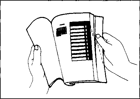 TO LOCATE WHAT YOU ARE LOOKING FOR:

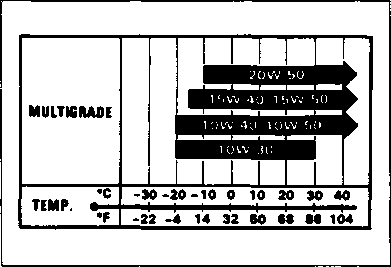 ENGINE OIL

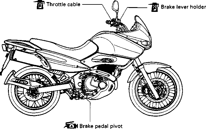

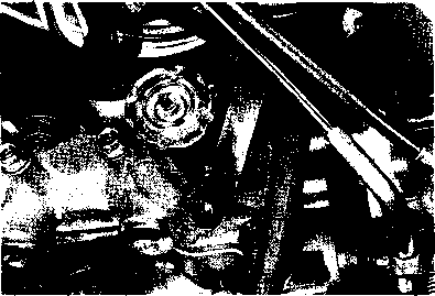 Both intake and exhaust valves must be checked and adjusted when the piston is at Top-Dead-Center (TDC) on
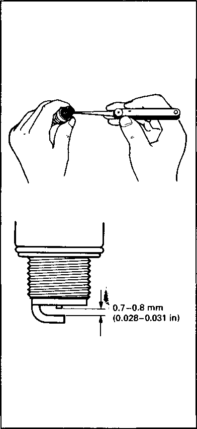 Confirm the thread size and reach when replacing the plug. If the reach is too short, carbon will be deposited on the screw portion of the plug hole and engine damage may result.
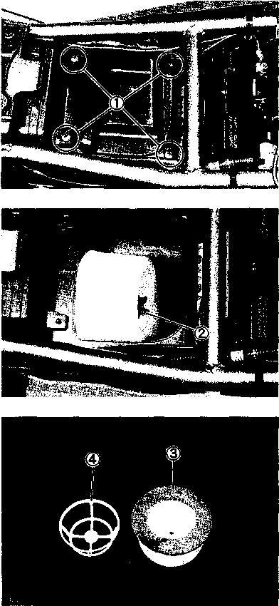

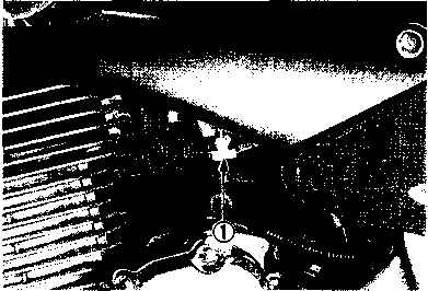 1 500 ± 50 r/min ... for Switzerland and Austria
 A WARNING
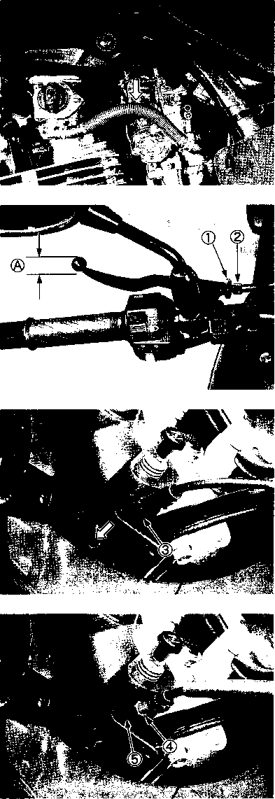 the clutch cable with motor oil
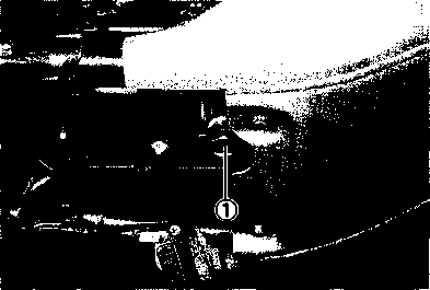
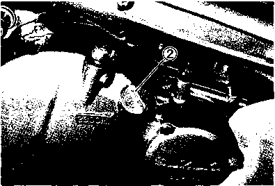

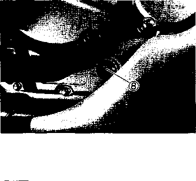 Overhaul engine: 2 600 ml (2.7/2.3 US/Imp qt)
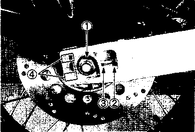
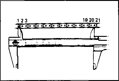
 [5 Rear axle nut: 110 N-m (11.0 kg-m, 79.5 Ib-ft)
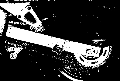 A CAUTION [2] *
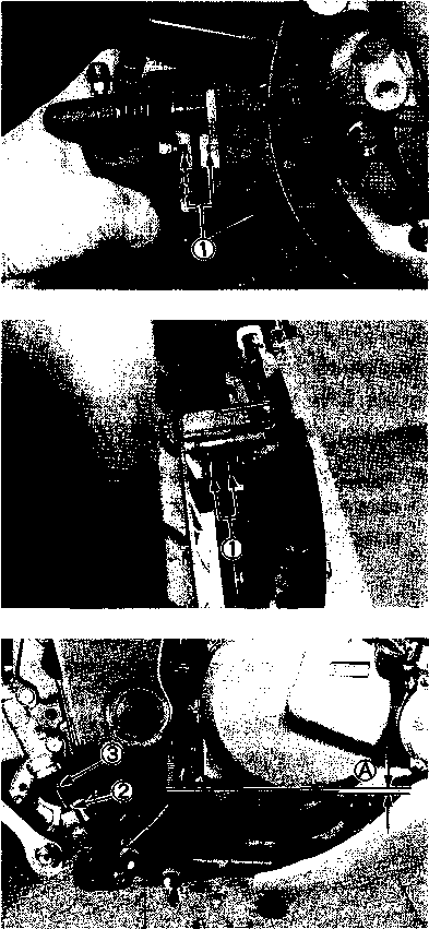 Brake pedal height ®: 5 mm (0.2 in)
 AIR BLEEDING THE BRAKE FLUID CIRCUIT

 Taper roller type bearings are used on the steering system for better handling. Steering should be adjusted properly for smooth turning of handlebars and safe running. Over- tight steering prevents smooth turning of the handlebars and too loose steering will cause poor stability. Check that there is no play in the front fork assembly by supporting the machine so that the front wheel is off the ground, with the wheel straight ahead, grasp the lower fork tubes near the axle and pull forward. If play is found, perform steering bearing adjustment as described in page 5-23 of this manual.
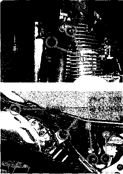 Tighten Initially at 1 000 km (600 miles, 2 months) and Every 12 000 km (7 500 miles, 24 months) thereafter. [4]
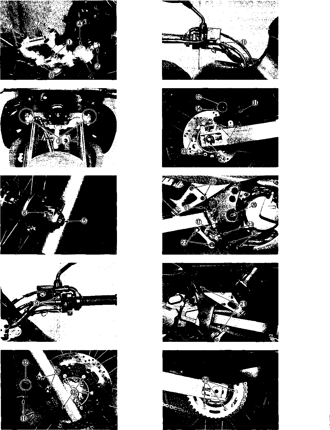
 Remove the parts concerned and test the compression
 Remove the oil pressure inspection plug.
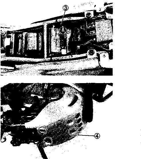
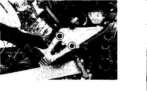 ENGINE REMOVAL AND REINSTALLATION
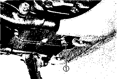

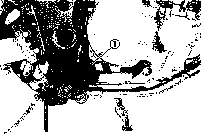


 Disconnect the starter motor lead wire (3) and crankcase breather hose 0.
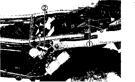


 • Remove the engine ground wire and lead wire clamp. [6]
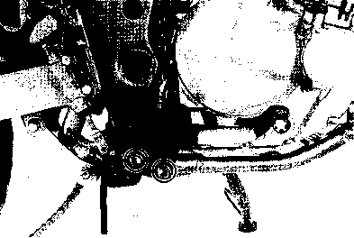
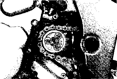

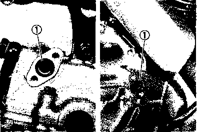
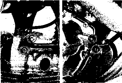
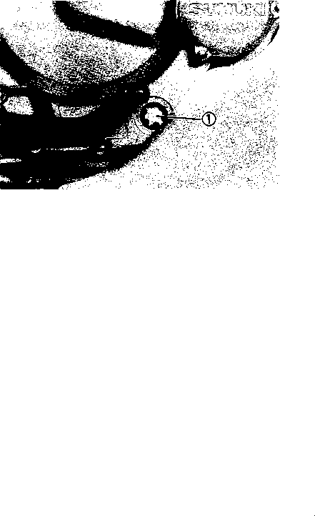 Start up the engine and allow it run for several minutes at idle speed and then stop it. Wait a few minutes and then check that the oil level remains between the marks on the oil level inspection window®.
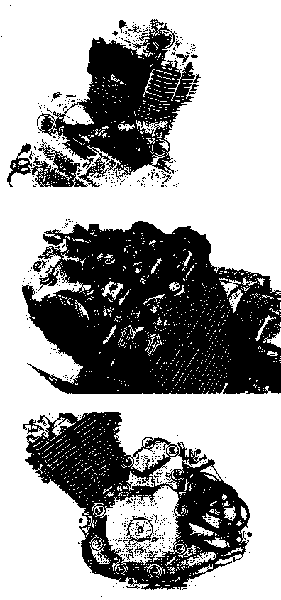


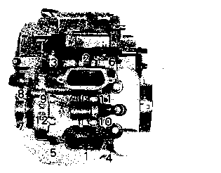
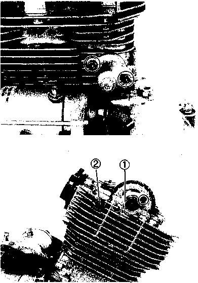
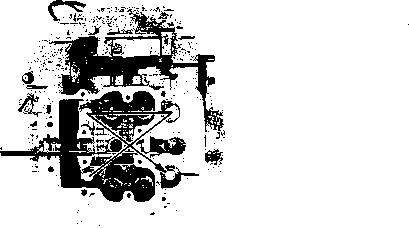


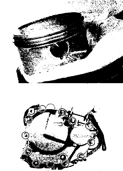
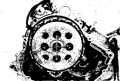
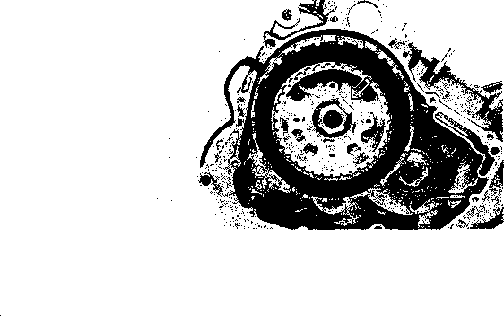 Remove the cam chain guide.
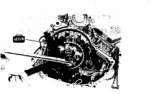


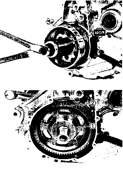


 Remove the cam chain.
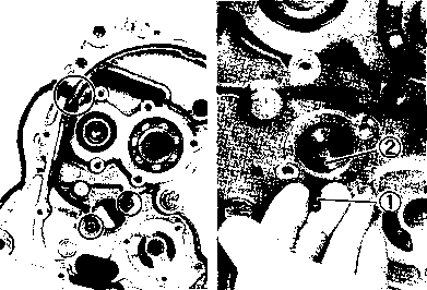
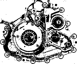
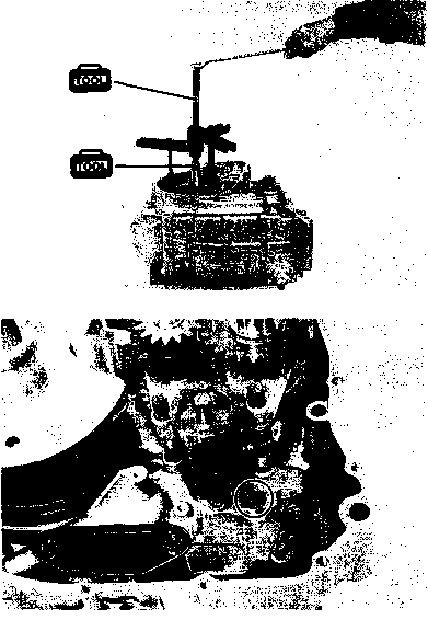 • Remove the breather cover.
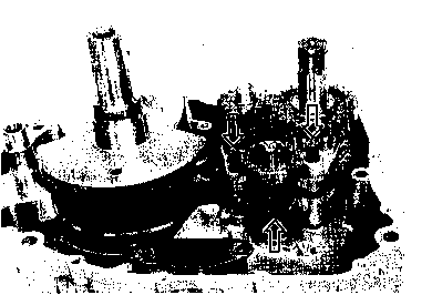


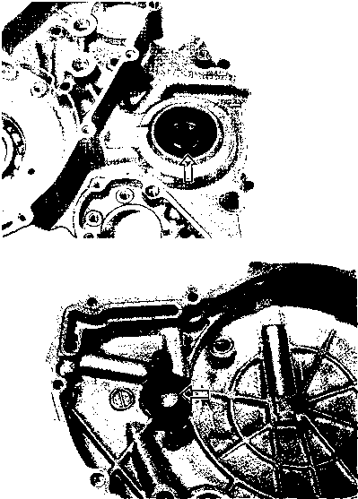
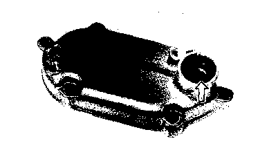
 Always use the special tool, otherwise the crankshaft may be misaligned.
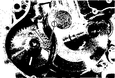

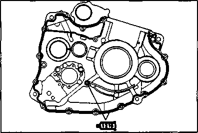
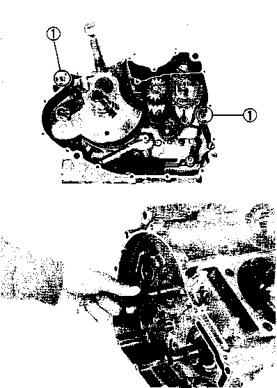

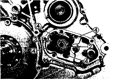
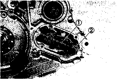

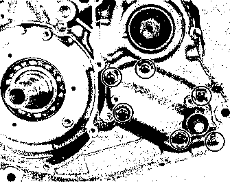

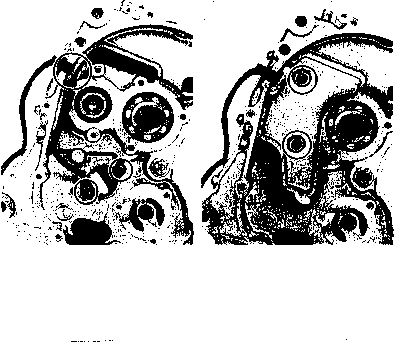 GEARSHIFT SHAFT
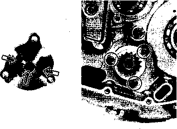


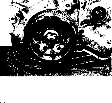 OIL PUMP

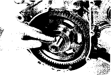

 99000-32030: THREAD LOCK SUPER "1303"
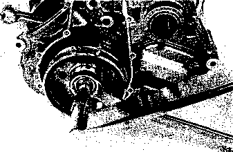
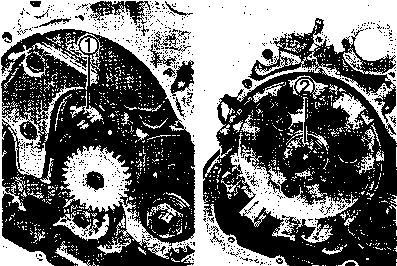
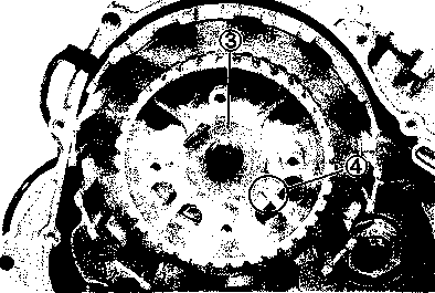

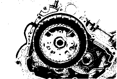 • Tighten the generator rotor bolt to the specified torque with the 36 mm offset wrench.

 • Tighten the clutch spring bolts in a crisscross pattern, to the specified torque.
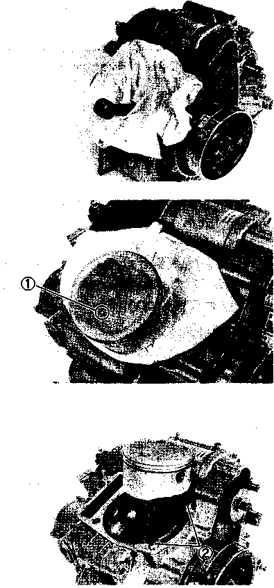

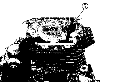
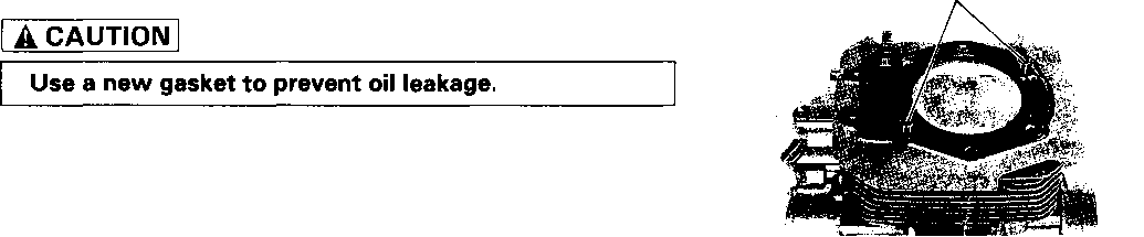
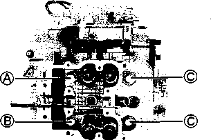

 И Cylinder base nut: 10 N*m (1.0 kg-m, 7.0 lb-ft)
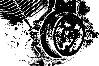
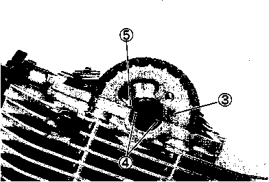
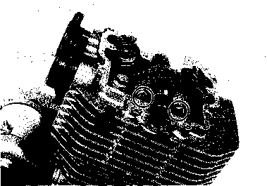 • Install the C-ring © into the ring groove in the cylinder head.
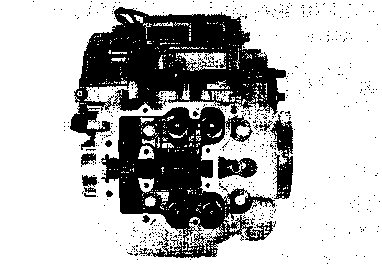

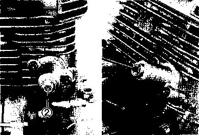
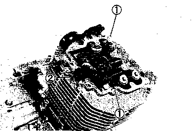
 Ч2Щ 99000-31110: SUZUKI BOND N0.1215
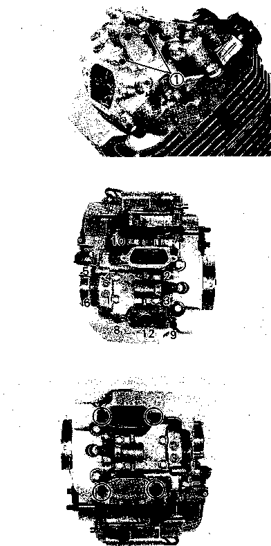
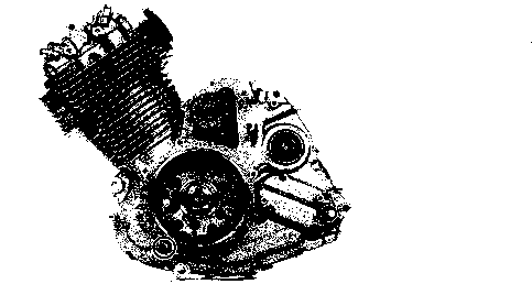
 (3): 20 N*m (2.0 kg-m, 14.5 Ib-ft)
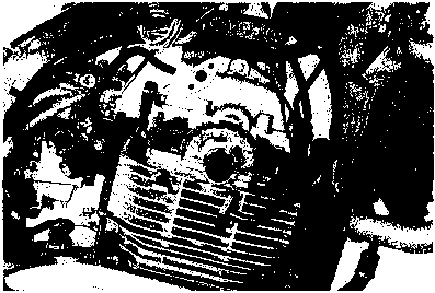
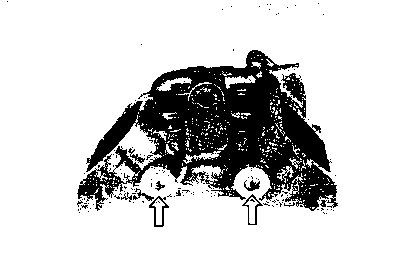
 ROCKER ARM REMOVAL
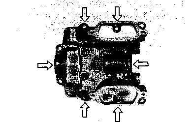
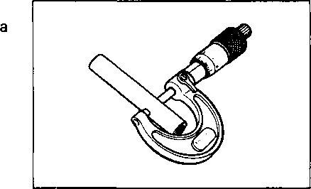
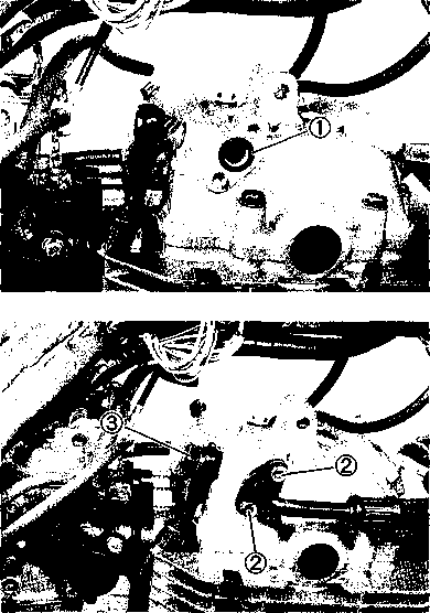
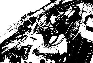
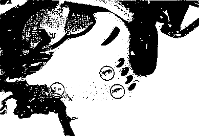 Tighten the engine protector bolts.
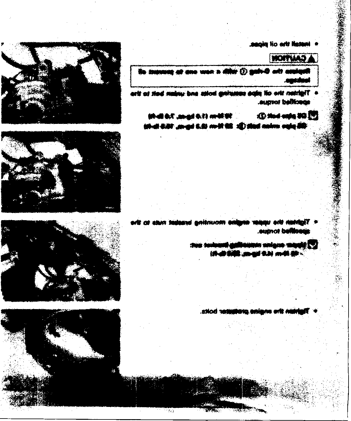

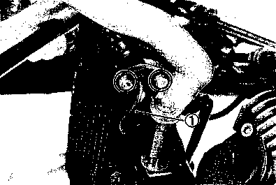
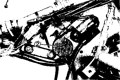


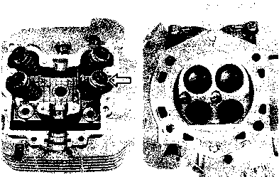


 If it does not operate smoothly, replace it.
 Camshaft journal oil clearance Service Limit: 0.150 mm (0.0059 in)
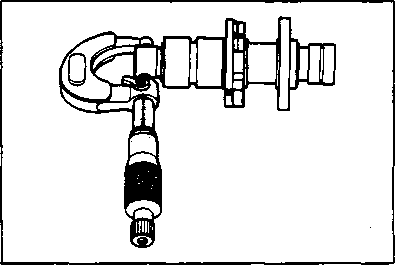
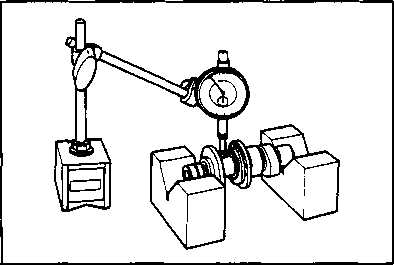

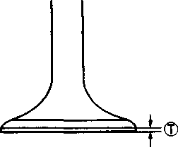
 Service Limit: 0.05 mm (0.002 in)


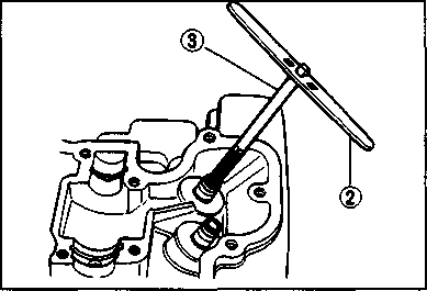
 The ring-like dye impression left on the valve face must be continuous without any breaks. In addition, the width of the dye ring, which is the valve seat width, must be within the following specification:
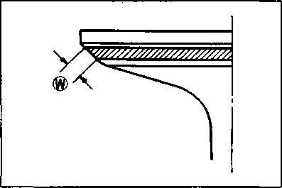

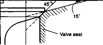
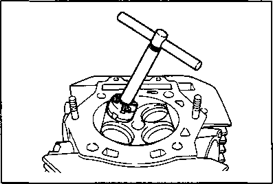 Cut only the minimum amount necessary from the seat.
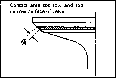 After servicing the valve seats, be sure to check the valve clearance after the cylinder head has been reinstalled. (Refer to page 2-3.)

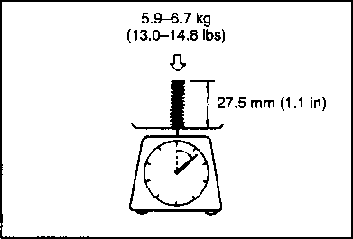 INNER: 5.Э-6.7 kg/27.5 mm (13.0-14.8 lbs/1.1 in) OUTER: 13.8-15.8 kg/31.0 mm (30.4-34.8 lbs/1.2 in)
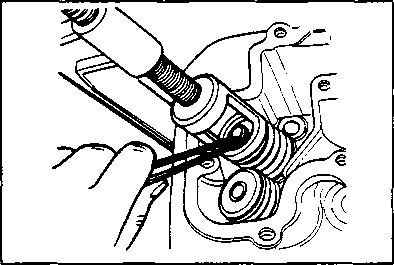
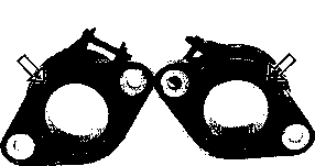
 РЧ Oil pipe bolt: 10 N*m (1.0 kg-m, 7.0 Ib-ft)

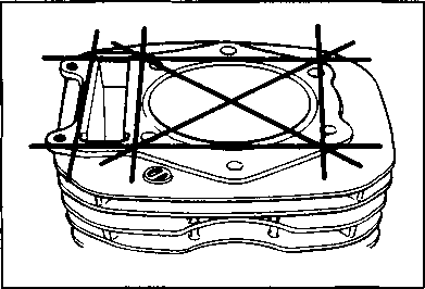

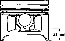 Remove the cylinder head cover.
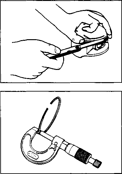
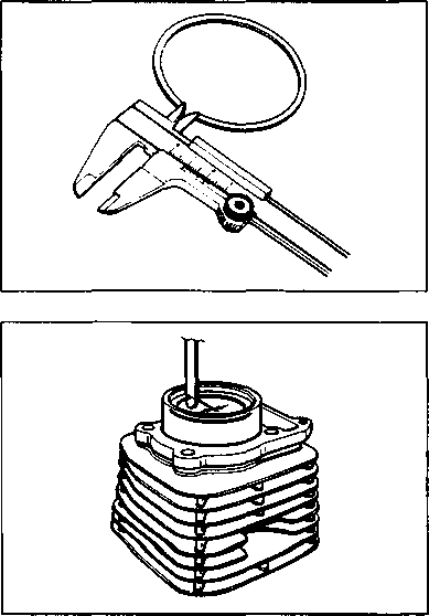 Install the piston ring into the piston ring groove. Insert the thickness gauge under the piston ring and measure the piston ring side clearance.
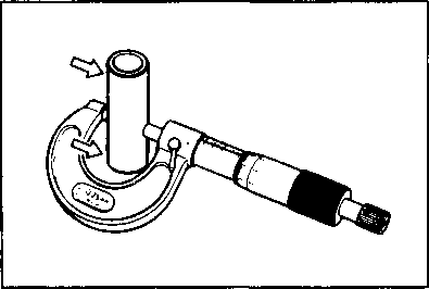
 Measure the piston pin bore inside diameter and use a micrometer to measure the piston pin outside diameter. If either is out of specification or the difference between these two measurements is more than the service limits, replace both the piston and piston pin.
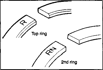


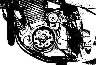
 Remove the right frame covers.
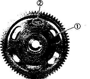
 Install the generator rotor in the reverse order of removal. Pay attention to the following points:
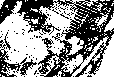
 Remove the oil pipe mounting bolts.
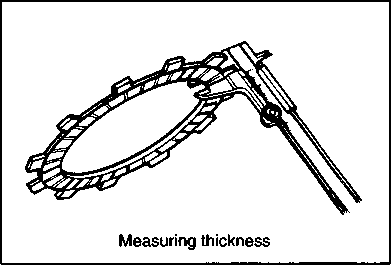
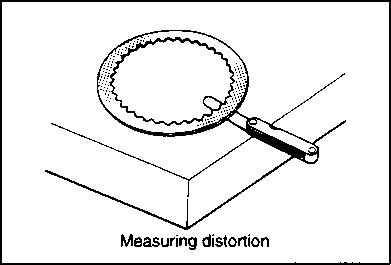
 Service Limit: 33.0 mm (1.30 in)
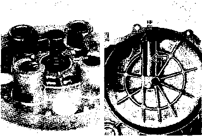
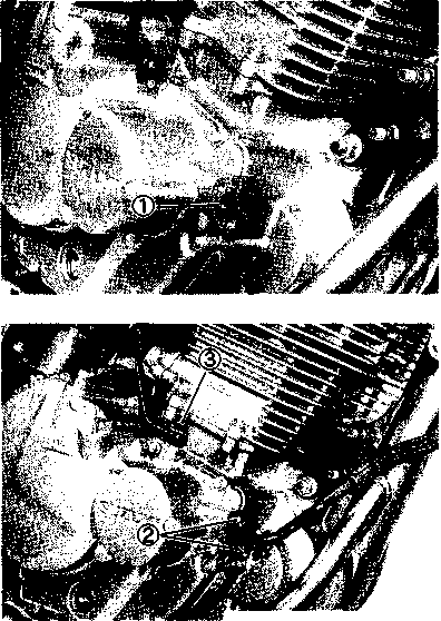 CLUTCH RELEASE BEARING
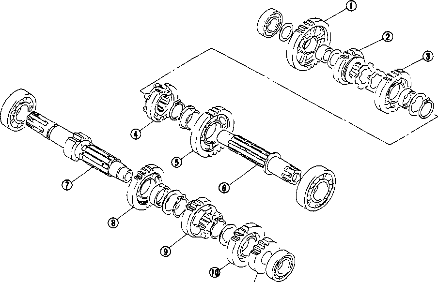

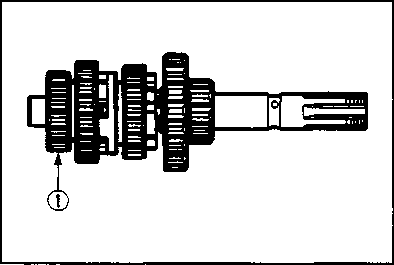
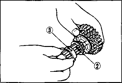 When installing a new circlip, pay attention to its direction. Fit the circlip to the side where the thrust is, as shown in the illustration. The rounded side should be against the gear surface.


 If the conrod small end inside diameter exceeds the service limit, replace the conrod.
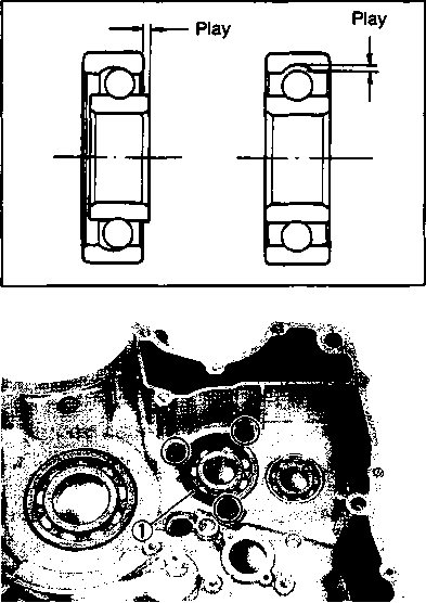
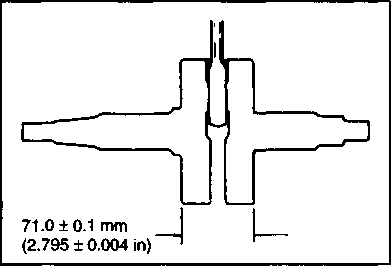

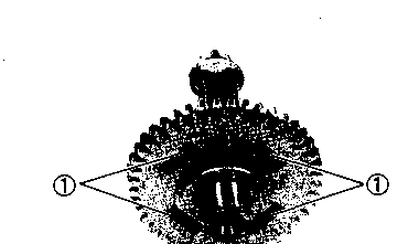 CRANKCASE BEARINGS
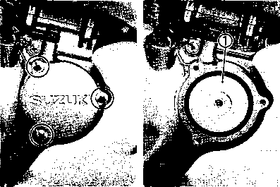 Remove the oil filter cap.
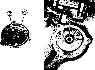
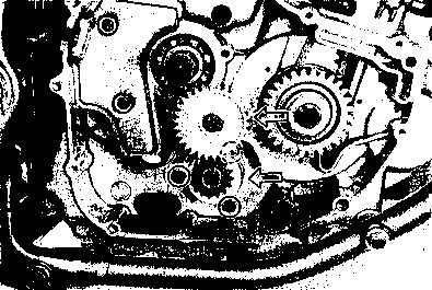
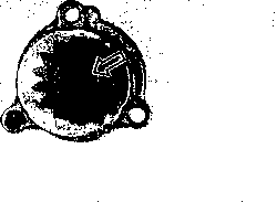 OIL PUMP
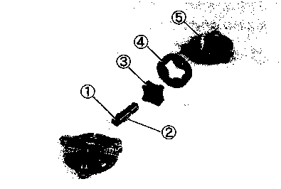
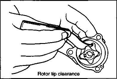
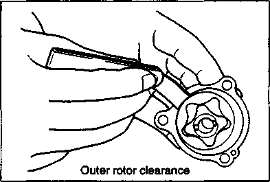
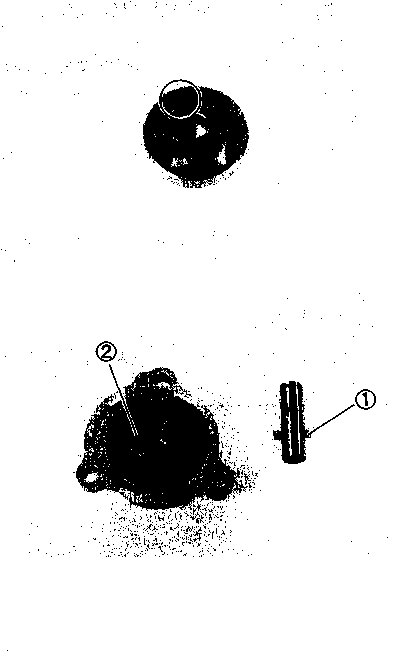 Insert the rotor shaft into the inner rotor by aligning the drive pin 0 with the slot 0 in the inner rotor.

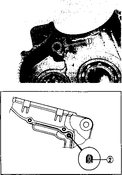 The removed oil jet (2) should be replaced with a new one.
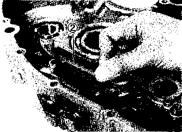
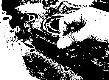 • When installing the oil sump filter into the right crankcase, align points 0, as shown.
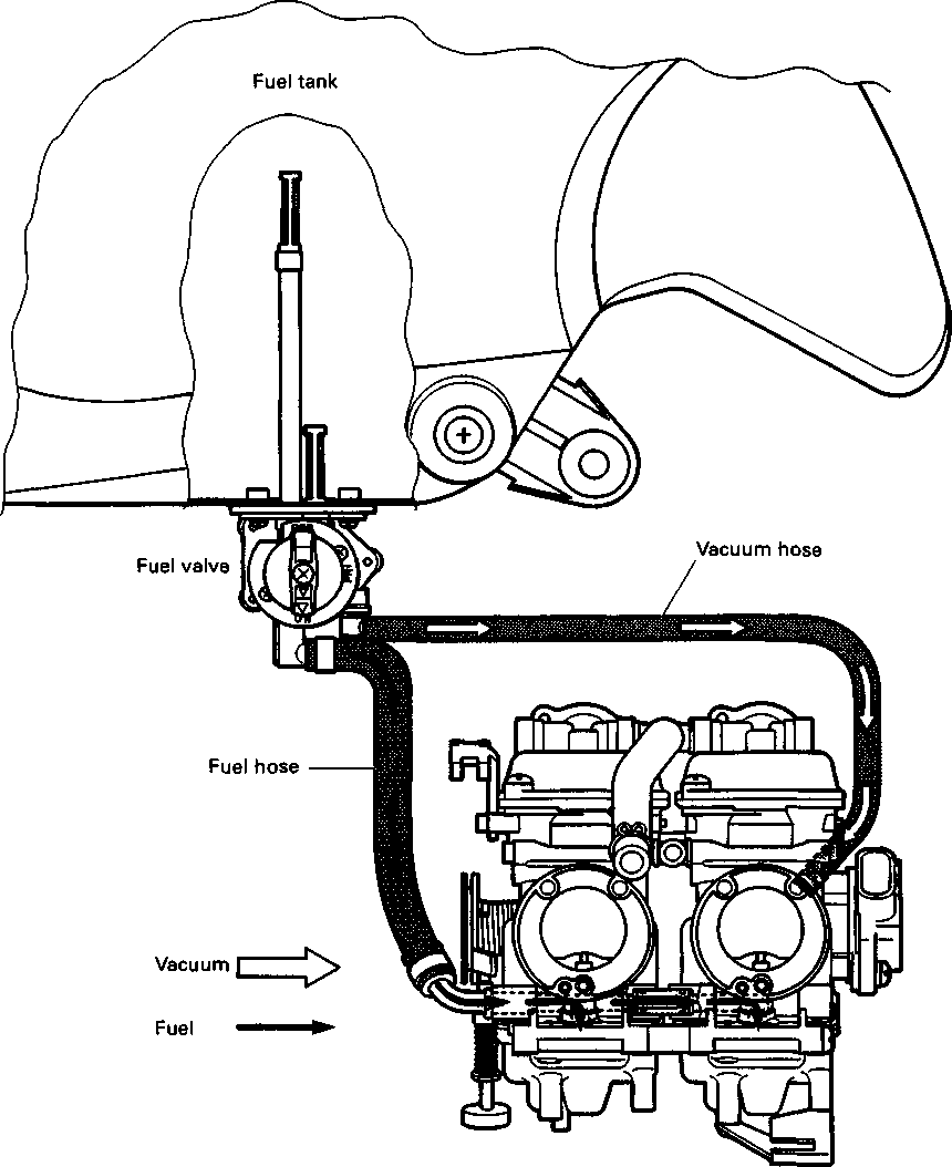


 If the fuel filter is dirty with sediment or rust, fuel will not flow smoothly and loss in engine power may result. Clean the fuel filter with compressed air. осмотр и чистка Если топливный фильтр загрязнен осадком или ржавчиной, топливо не будет течь гладко и может привести к потере мощности двигателя. Очистить топливный фильтр сжатым воздухом.
  I.D. NO. LOCATION
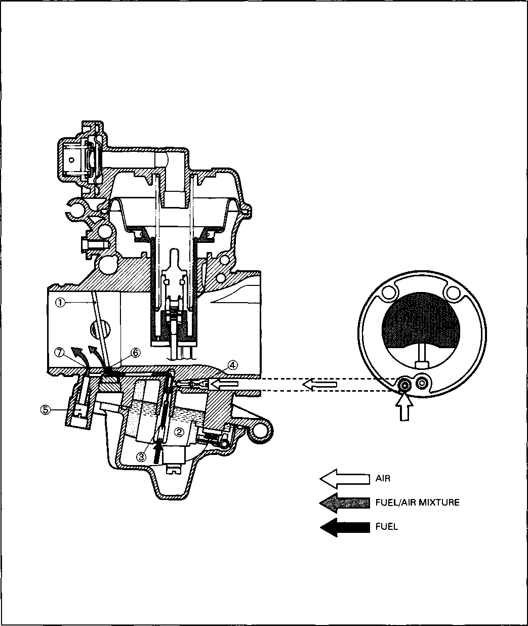


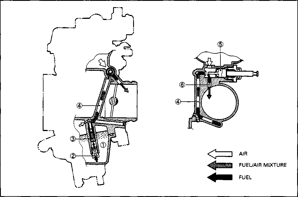
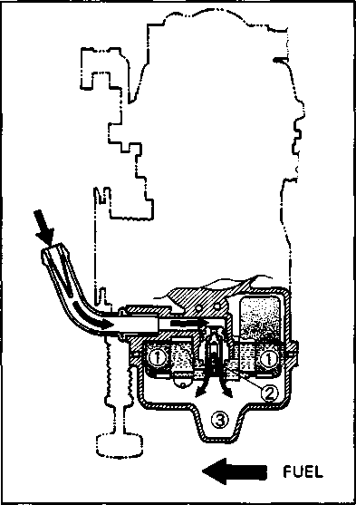 FLOAT SYSTEM
 Remove the seat and frame covers. (Refer to page 5-2.)

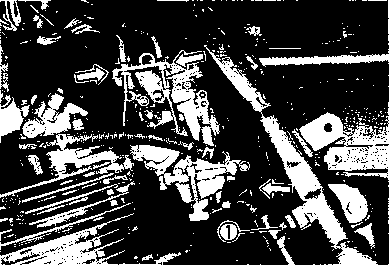
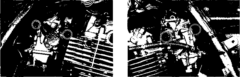


 Avoid removing the throttle position sensor from the carburetor body unless you really need to do so.
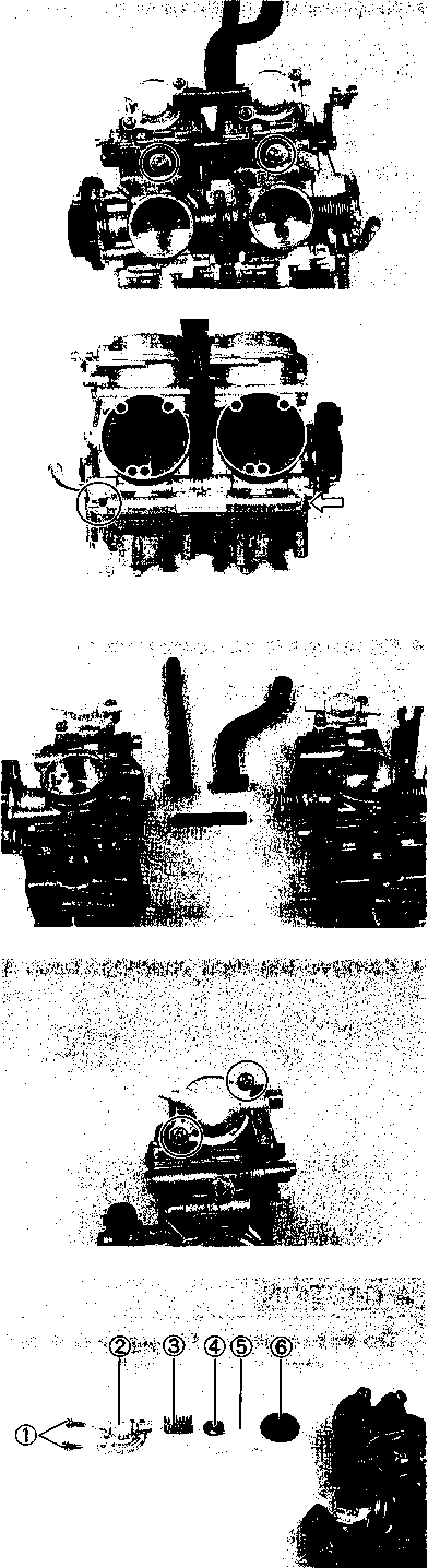 • Remove the starter shaft lever.
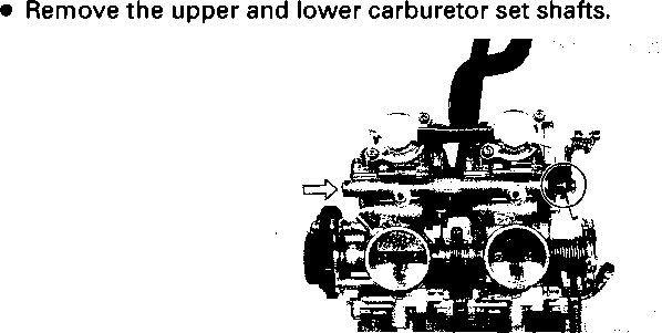

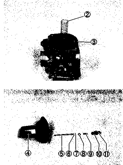

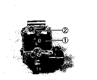
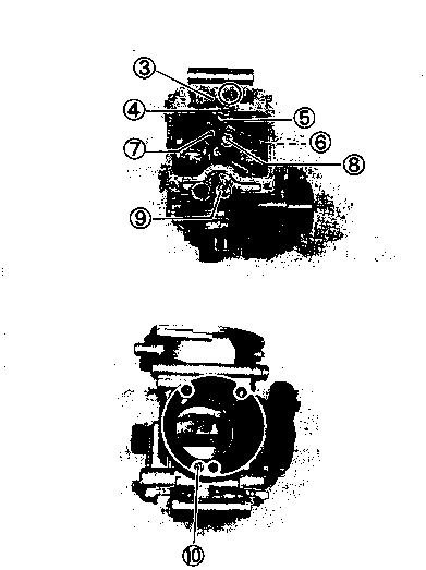
 Install new plug by tapping it into place with a punch.
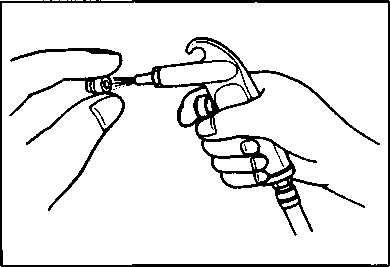 Do not use wire to clean jets or passageways. Wire can damage jets and passageways. If the components cannot be cleaned with a spray cleaner it may be necessary to use a dip-type cleaning solution and allow them to soak. Always follow the chemical manufacturer's instructions for proper use and cleaning of the carburetor components. [28] [29]
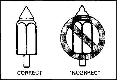

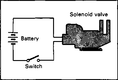 NEEDLE VALVE INSPECTION


 Check the V.T.V. in the following tests.
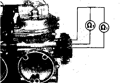

 THROTTLE POSITION SENSOR POSITIONING
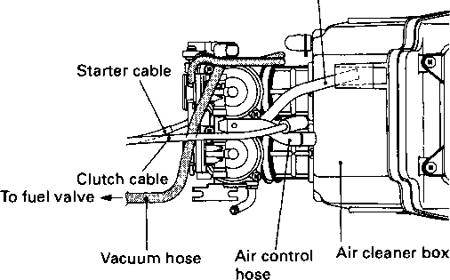

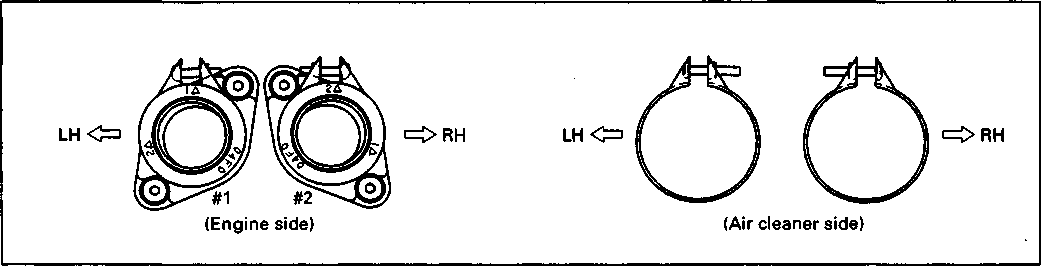


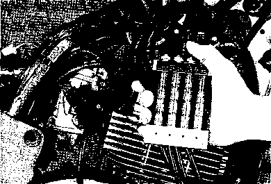
 Check and adjust the carburetor synchronization among four carburetors following the procedures below.
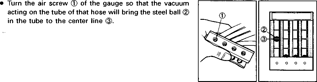

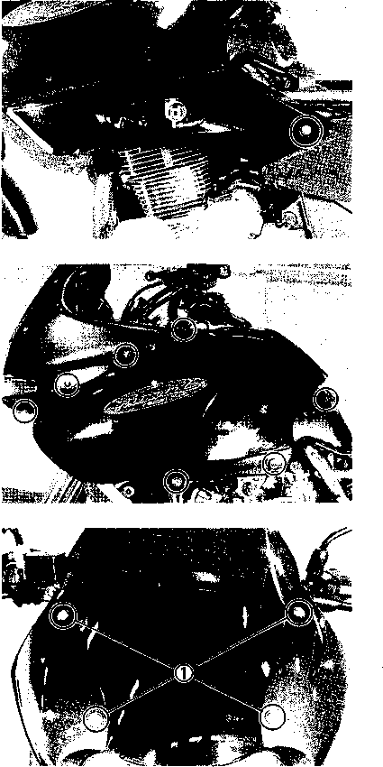
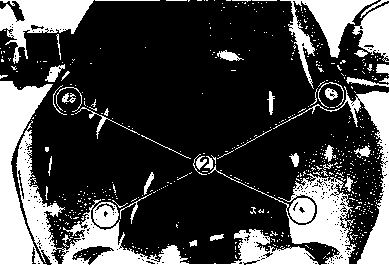
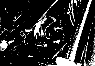 • Disconnect the turn signals, speed sensor and headlight lead wire couplers.
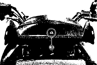 Disconnect the speedometer coupler.
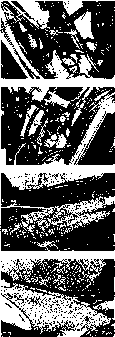 Remount the frame covers and fairing in the reverse order of their removal.
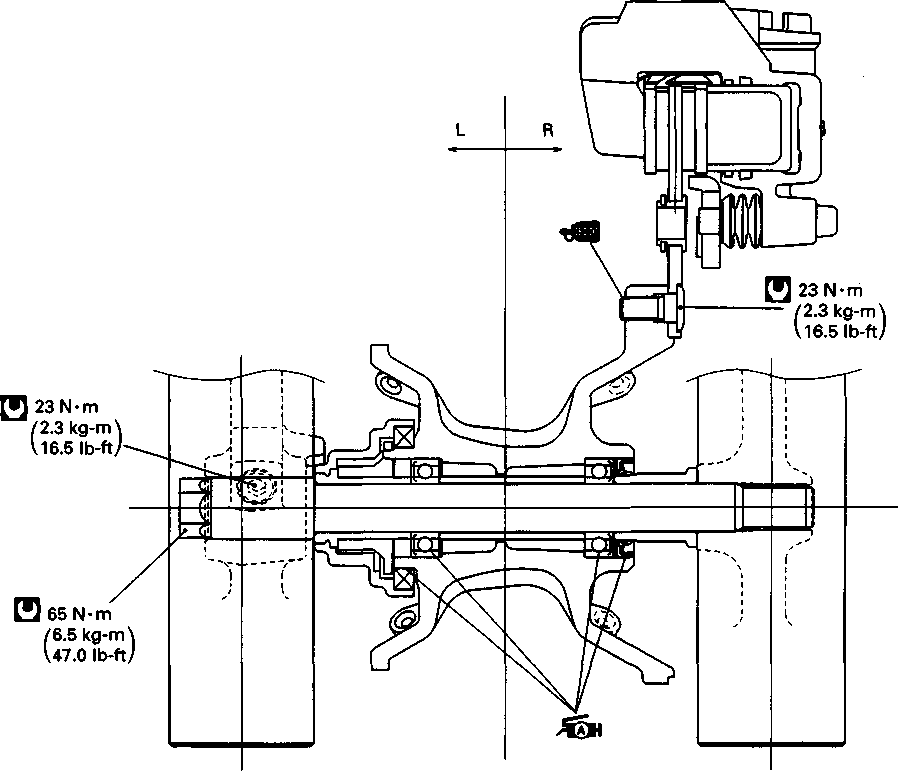
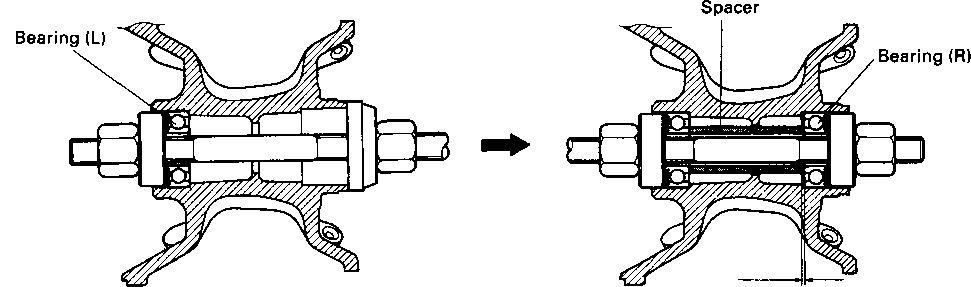


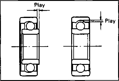 • Remove the speed sensor guides ф.
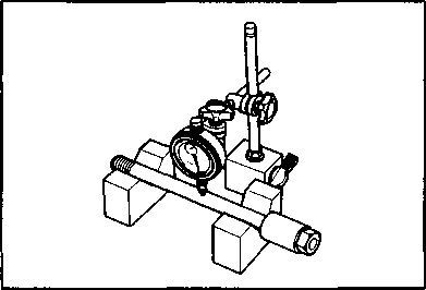

 Drive out the both bearing with the special tool in the following procedures.
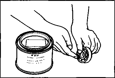
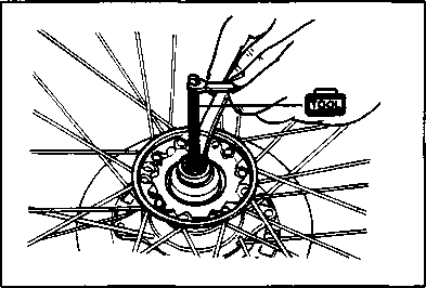


 Reassemble and remount the front wheel in the reverse order of removal and disassembly, and also carry out the following steps:
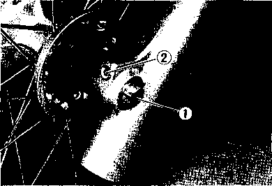
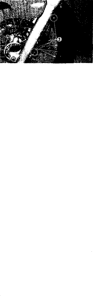 Tighten the axle holder bolt (D to the specified torque.
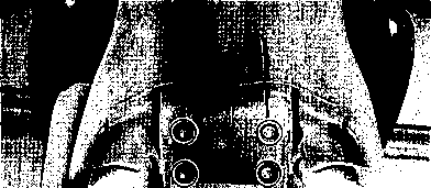
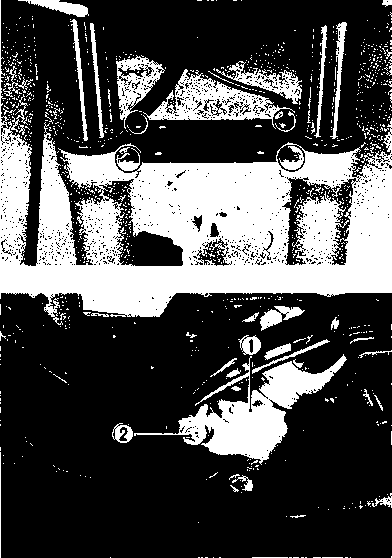
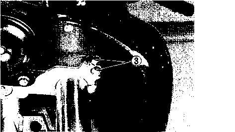

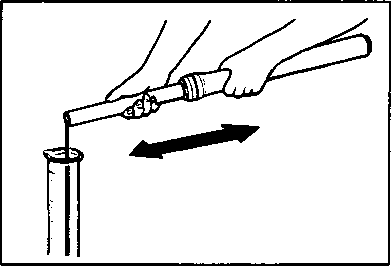
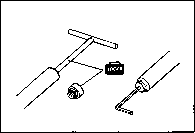


 DAMPER ROD RING

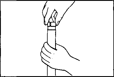


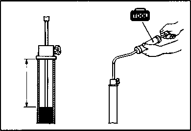 • For the fork oil, be sure to use a front fork oil whose viscosity rating meets specifications below.
 FRONT FORK REMOUNTING
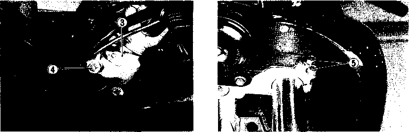
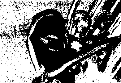 Remove the horn lead wire coupler.


 • Remove the horn.
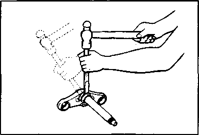

 Inspect the play of dampers by hands while fixing it in the steering stem upper bracket. If the play can be found, replace the dampers.
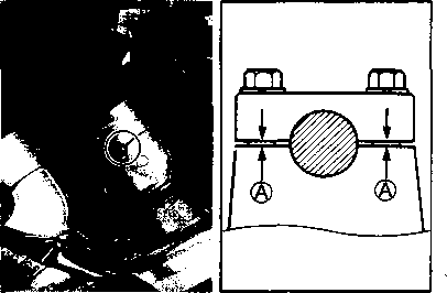
 After performing the adjustment and installing the steering stem upper bracket, "rock" the front wheel assembly forward and back to ensure that there is no play and that the procedure was accomplished correctly. Finally check to be sure that the steering stem moves freely from left to right with own weight. If play or stiffness is noticeable, re-adjust the steering stem nut.
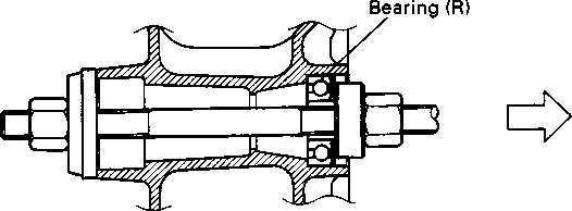


 Do not operate the brake pedal while dismounting the rear wheel.
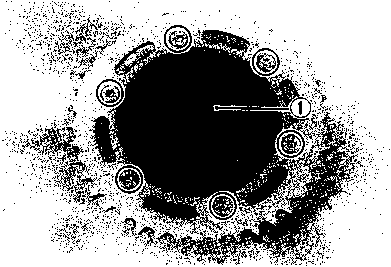

 • Remove the rear sprocket mounting drum from the wheel.


 The sealed cover of the bearing must face outside.

 £5 Axle nut: 110 N-m (11.0 kg-m, 79.5 Ib-ft)
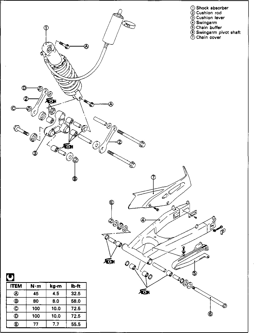
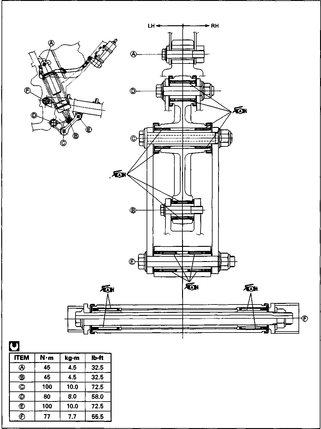

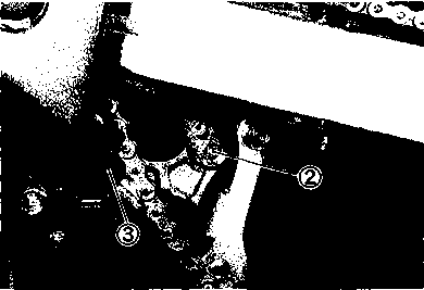

 Remove the seat and left frame cover. (Refer to page 5-4.)
 Take off the hose from the clamps
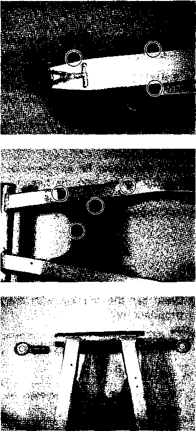 • Remove the swingarm dust seals and spacers.
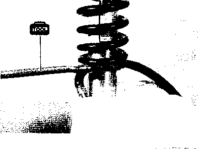
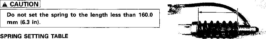
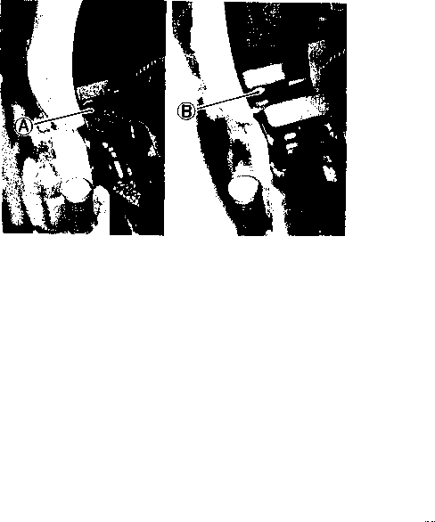 A: Rubber cap B: Adjuster
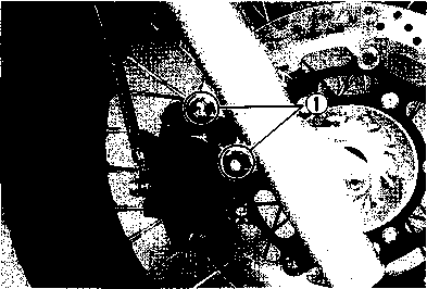
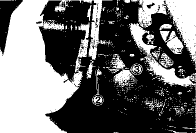

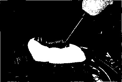
 Bleed air in the brake fluid circuit. (Refer to page 2-12.)
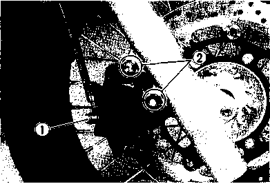 Remove the brake hose from the caliper by removing the union bolt ф and catch the brake fluid in a suitable receptacle.
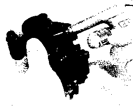 A CAUTION____________________________________________
 • Remove the dust seals and piston seals.
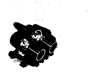
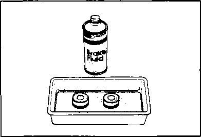
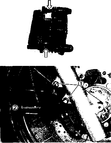 CALIPER
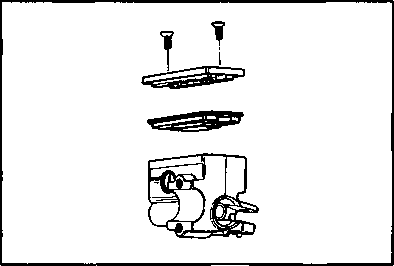
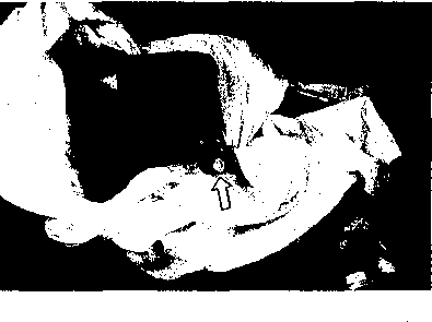

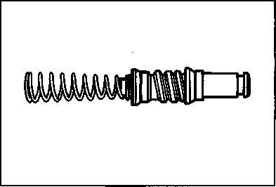
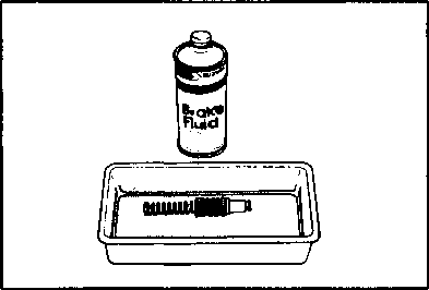
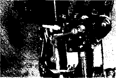

 BRAKE PAD REPLACEMENT
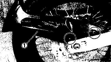

 Bleed air in the brake fluid circuit. (Refer to page 2-12.)
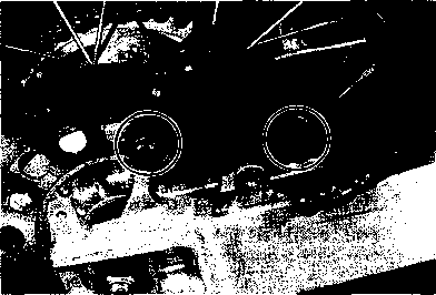
 Do not reuse the removed seals to prevent fluid leakage.
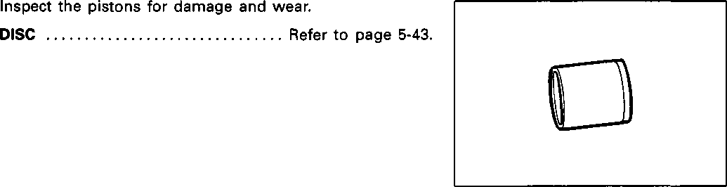
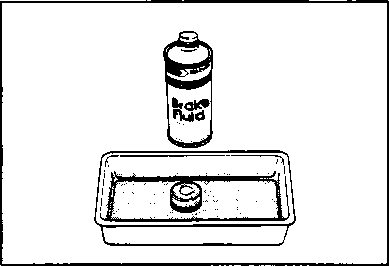 Bleed air from the system after reassembling the caliper. (Refer to page 2-12.)
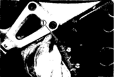


 MASTER CYLINDER REMOVAL AND DISASSEMBLY
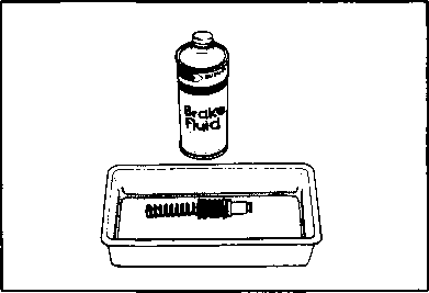
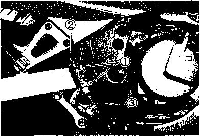

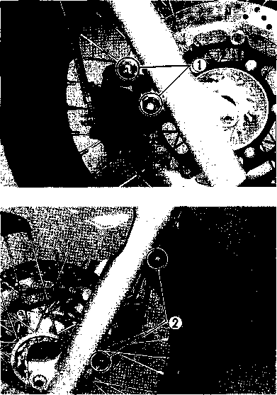
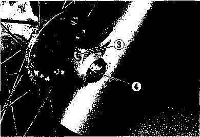
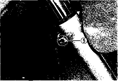 REMOVAL AND DISASSEMBLY
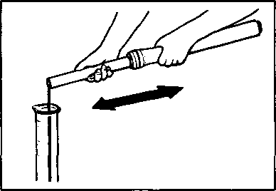 • Remove the front fender brace.
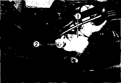


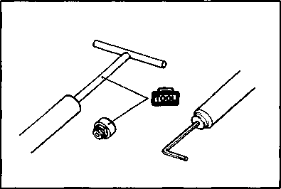

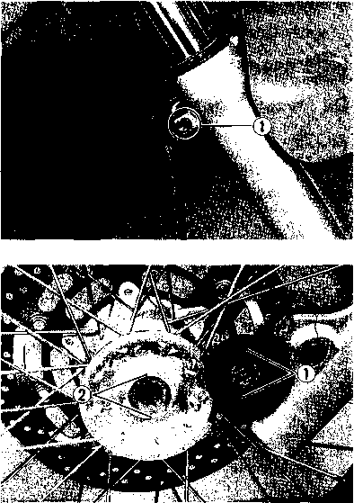
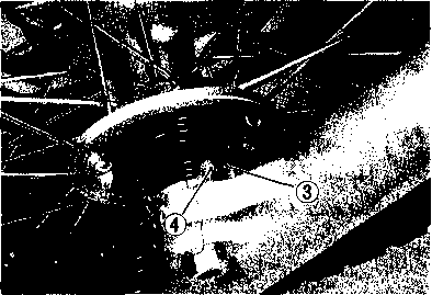


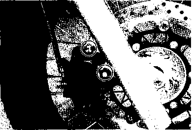 Clamp the speed sensor wire harness to the white marked part. [51]
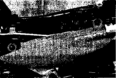
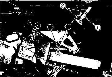
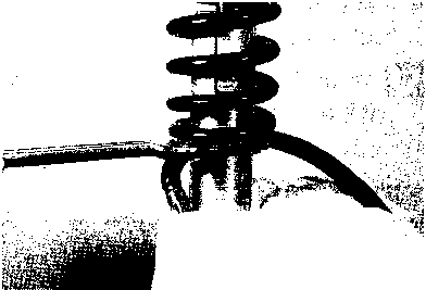
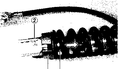
 • Remove the seat and left frame cover.
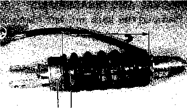
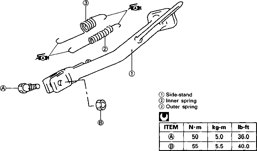
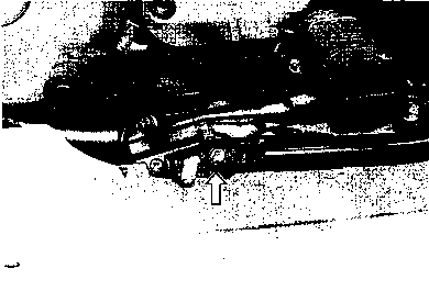

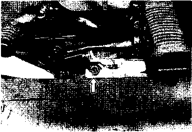
 STARTER MOTOR INSPECTION .......................... 6-13
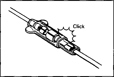
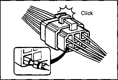

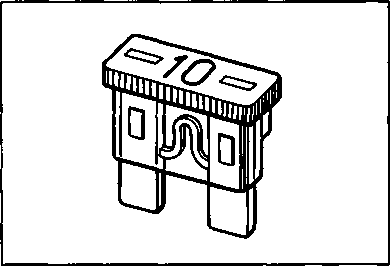
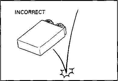 When inspecting these parts, follow inspection instruction strictly. Neglecting proper procedure may cause damage to these parts.

 Before using the multi circuit tester, read the instruction manual.
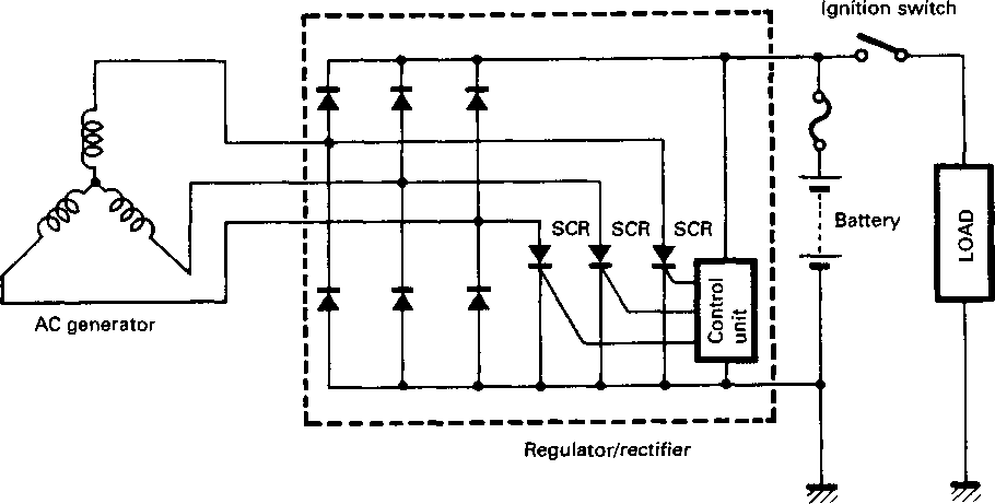

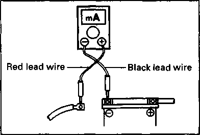

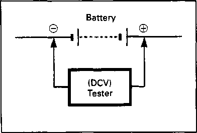 BATTERY LEAK CURRENT INSPECTION
 Remove the seat and right frame cover.
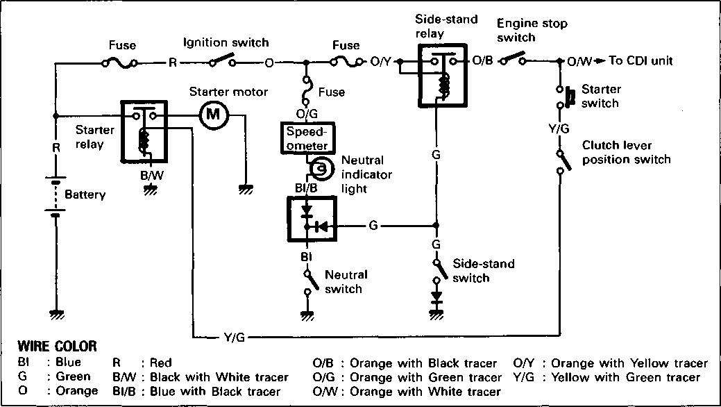
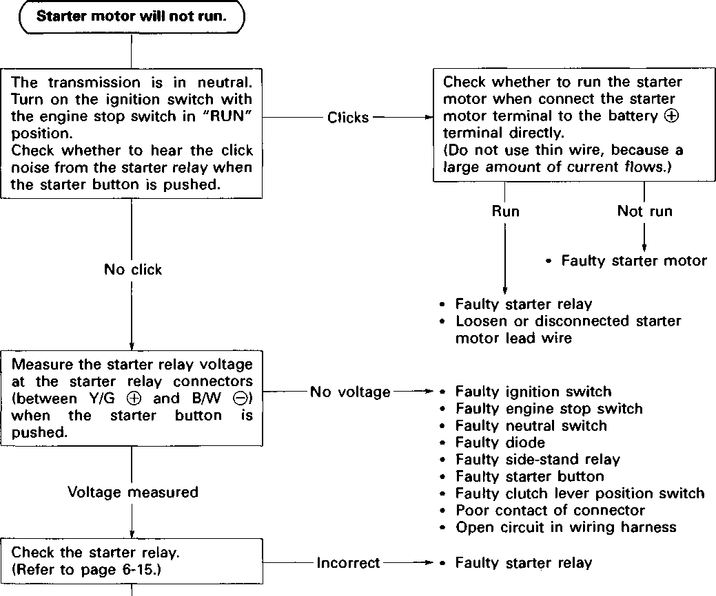
 STARTER MOTOR REMOVAL AND DISASSEMBLY
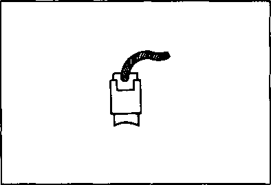 If the brush has failed, replace the brush sub ass'y-
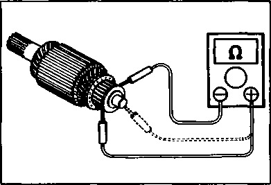
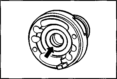
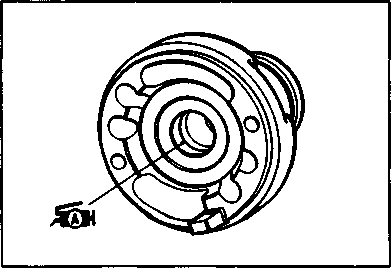 COMMUTATOR
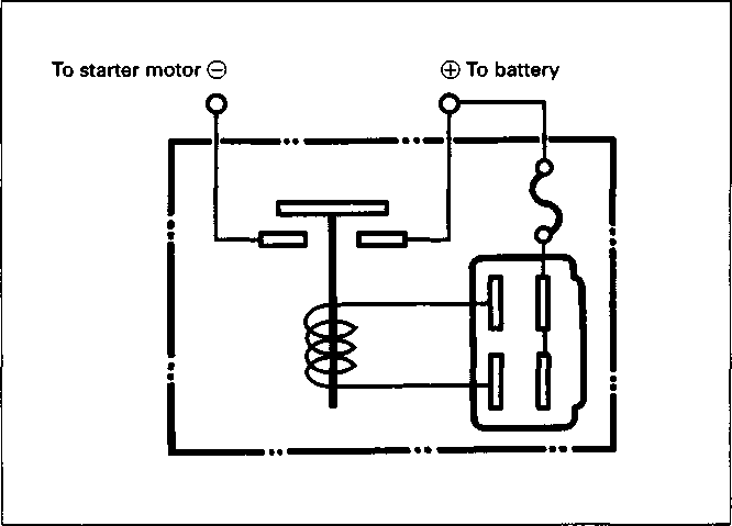 STARTER RELAY CIRCUIT DIAGRAM


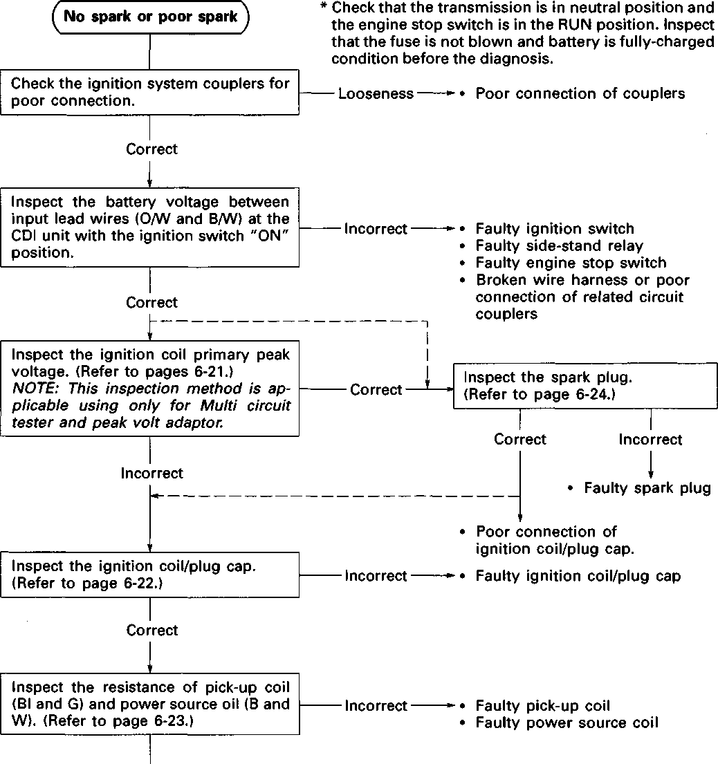

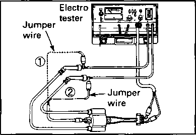
 Tester knob indication: Resistance (£2)
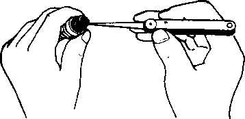
 • Disassemble the combination meter as follows.
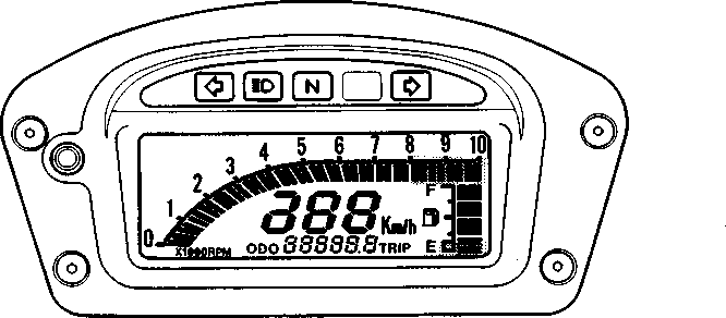


 SPEEDOMETER INSPECTION
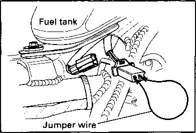
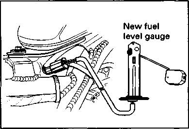
 FUEL METER
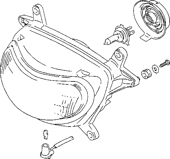
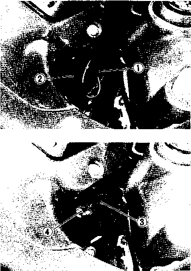
 When replacing the headlight bulb, do not touch the glass. Grasp the new bulb with a clean cloth. If you touch the bulb with your bare hands, clean it with a cloth moistened with alcohol or soapy water to prevent early failure. [57] [58]
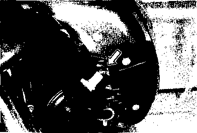
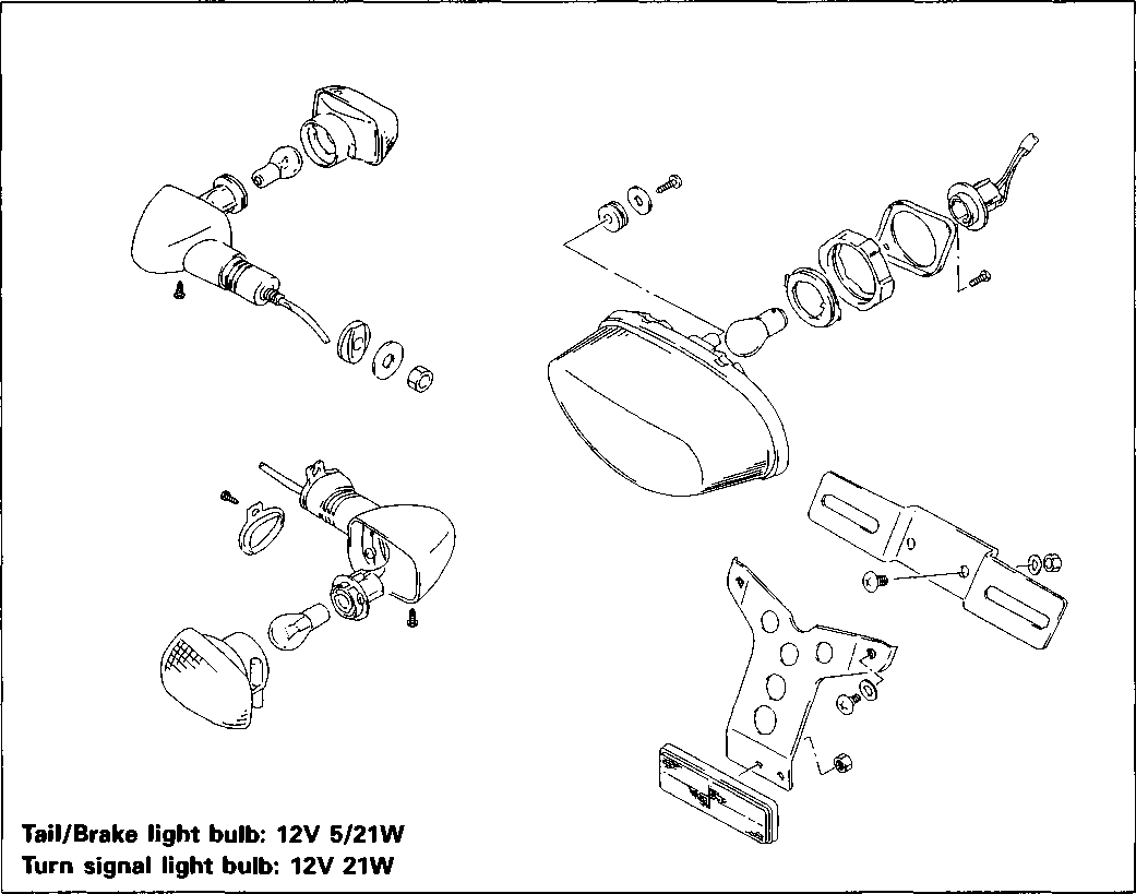
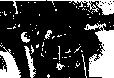 BULB REPLACEMENT Tail/Brake light


 Be sure that the battery used is in full-charged condition.
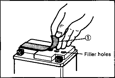
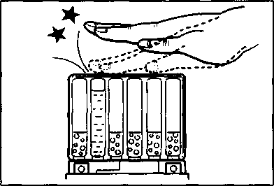
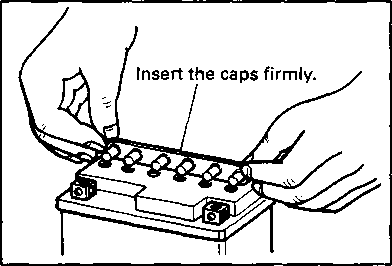


 Visually inspect the surface of the battery container. If any signs of cracking or electrolyte leakage from the sides of the battery have occurred, replace the battery with a new one. If the battery terminals are found to be coated with rust or an acidic white powdery substance, then this can be cleaned away with sandpaper.
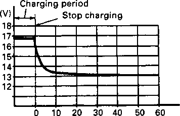


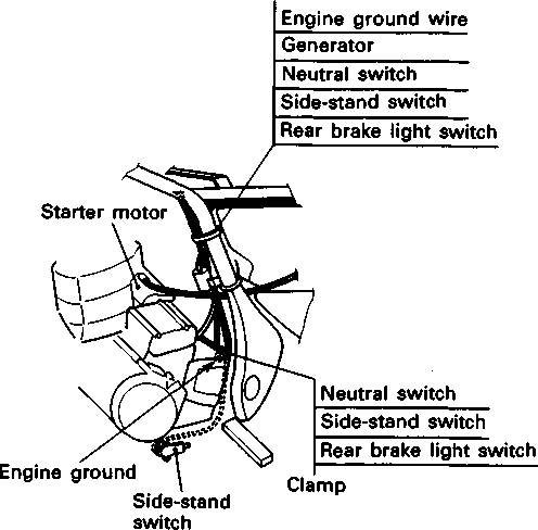
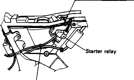
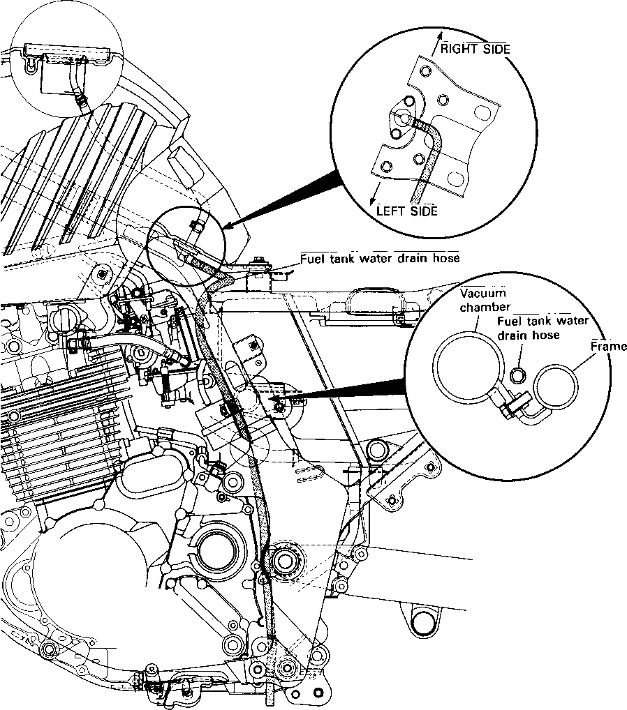

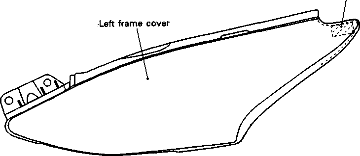


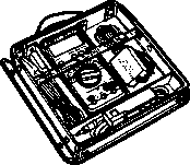


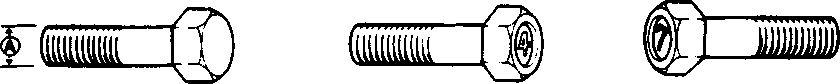
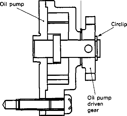


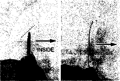
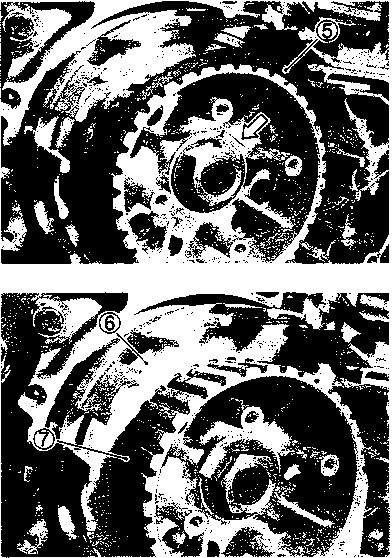 Install the spacer with the primary driven gear assembly.
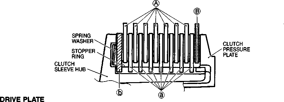


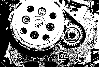
 • Install the clutch pressure plate with clutch release rack.
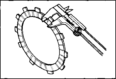
 09900-20803: Thickness gauge
 ©Windscreen ® Side fairing (R)
 • Remove the fuel tank covers (right and left).
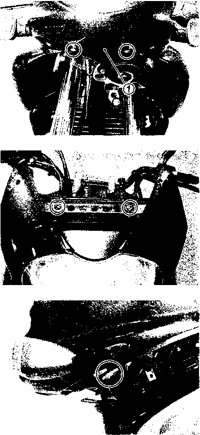

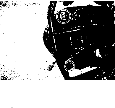 • Remove the center fairing ©.
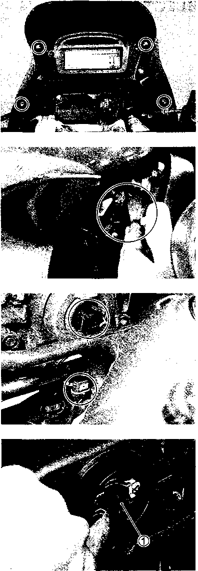
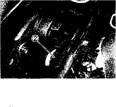 HEADLIGHT AND POSITION LIGHT
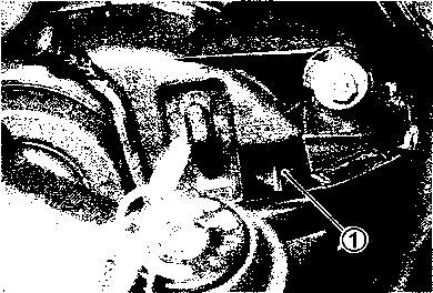
 Remove the speedometer.
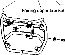
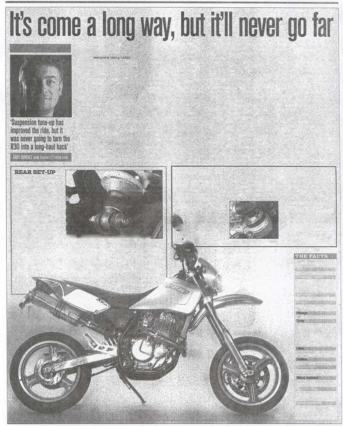 28 ВШОЙ СУШ: EE3S?S OCTOBER 16,2002
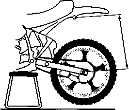 the rear frame, e.g. one of the fastening bolts on the mudguard
 The difference between both values is the rear ride height sag. The rear ride height sag of the cold shock absorber must be between 15 and 20 millimetres. Between these two extremes - and no further - you can vary the spring preload. When the shock absorber gets hot, the rear ride height sag will decrease. However, it should never occur that the shock absorber goes all the way up and does not sag again (rear ride height sag 0 mm). In order to determine whether the main spring is too hard or too soft, the total sag must be determined:
 • the rider gets on the motorcycle (wearing normal riding gear) and puts one foot on the footrest, using the other foot on the ground to steady the motorcycle.
 It is best to change the spring preload of the shock absorber when the shock absorber is dismantled.
 You will need special spring pliers in order to dismantle the white steel main spring of the shock absorber. Obviously the shock absorber will have to be completely removed from the motorcycle in order to replace the spring.
 • Take a steel ruler or a folding ruler and measure the length of the unloaded main spring from the bottom to the top side. In a similar manner measure the distance between the spring plates on the shock absorber. The difference between these two will determine the preload.
 Before any work can be carried out on the shock absorber, you will first have to remove the nitrogen pressure. To do this, first set the rebound damping to Setting 1. Then, using a screwdriver, remove the rubber cap from the reservoir and. by unscrewing the filler hole on the reservoir with the appropriate tool, let the pressure escape. Always do this before you dismantle the shock absorber and be sure to direct the shock absorber away from you when letting the nitrogen escape.
 draining the oil

 Clamp the spindle in the bench vice by the head and unscrew the spindle nut with a No. 22 ring spanner. Use a small screwdriver on the spindle in order to remove the piston and both shim assemblies from the spindle in one movement and in the right sequence and place them aside.
 О
О fitting the spindle
 is slid onto the spindle will be needed to fit the components on the spindle. One by one the large 'O' ring, the scraper, the spindle holder, the spacer and the shim assemblies and the piston are carefully slid over the spindle axle. Then remove the fitting mandrel and tighten the spindle nut with a torque of AO Nm. Set the damping to Setting 1: the spindle is ready to be fitted in the shock absorber.

 fitting the spindle
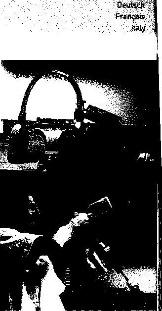

 When the bleed tube has been removed, the compression control mechanism can be re-assembled. Turn the mechanism anti-clockwise until the disks are clamped against one another. Replace the 'O' rings with new ones. Carefully push the mechanism to the bottom and take care that the clamping pin lies across from the brand symbol at the bottom. Press the mechanism tightly and fit the round retaining spring sharp side up. Check whether the retaining spring fits fully into the groove by trying to pull the mechanism upward with a pair of pliers.
 Syphon off the surplus oil and. using a little grease, place the adjustable ball-bearing in the position that is closest to the pressure reservoir. Then set the adjustment switch to Setting 1. The shock absorber can now be pressurised with nitrogen.
 At the top of the pressure reservoir. turn the nitrogen filler bolt, fitted with a new 'O' ring, a few turns into the reservoir. Place the shock absorber under the filler apparatus with nitrogen and set the pressure to 10 bar. Firmly tighten the filler bolt and check whether the bolt is leaking. Then press the rubber cap with the message 'Do not open' into the reservoir.
 You can now also replace the spring very easily. Remove the open-ended spanner from the hydraulic buffer and remove the spring from the fork upright. You can now install a heavier or lighter spring. You should tighten the hydraulic buffer using a 20Nm turning moment.
 Б
Б Regularly - e.g. after each race • remove the dust hood from the outer tube and clean both the inner tube and the outer tube and the gasket. Spray the dust hood and the gasket with silicon spray after cleaning.