Заглавная страница Избранные статьи Случайная статья Познавательные статьи Новые добавления Обратная связь FAQ Написать работу КАТЕГОРИИ: ТОП 10 на сайте Приготовление дезинфицирующих растворов различной концентрацииТехника нижней прямой подачи мяча. Франко-прусская война (причины и последствия) Организация работы процедурного кабинета Смысловое и механическое запоминание, их место и роль в усвоении знаний Коммуникативные барьеры и пути их преодоления Обработка изделий медицинского назначения многократного применения Образцы текста публицистического стиля Четыре типа изменения баланса Задачи с ответами для Всероссийской олимпиады по праву 
Мы поможем в написании ваших работ! ЗНАЕТЕ ЛИ ВЫ?
Влияние общества на человека
Приготовление дезинфицирующих растворов различной концентрации Практические работы по географии для 6 класса Организация работы процедурного кабинета Изменения в неживой природе осенью Уборка процедурного кабинета Сольфеджио. Все правила по сольфеджио Балочные системы. Определение реакций опор и моментов защемления |
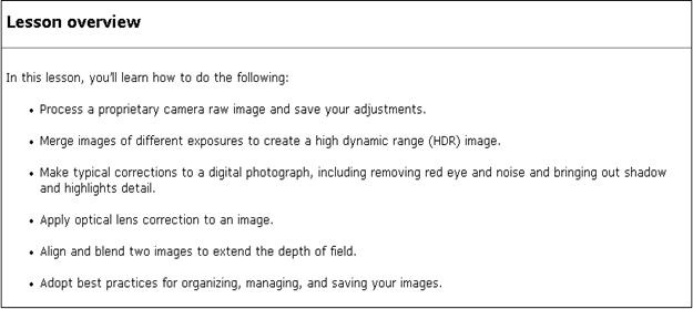
What do you know about Vector Images?Содержание книги
Поиск на нашем сайте
2. What do you know about RasterVector Images? 3. How scaling is done in vector images: 4. Where vector images can be used
Lecture №17-18. Drawing 1 Raster vs. Vector 2 Shape Layers and Shape Options 3 Using the Shape, Pen, Anchor Point Tools 4 Using the Paths Palette 5 Working the Paths
Understanding the differences between Illustrator and Photoshop can range from confusing to downright frustrating for those who are new to graphics and image editing. Which application should you use for your project? It really boils down to having an understanding not only of what you wish to achieve, but also having a firm grasp on the key differences between Photoshop and Illustrator; what are their strengths? Their weaknesses? Before we can compare Photoshop vs Illustrator, we must understand the difference between raster and vector graphics.
Raster and Photoshop First off, a raster graphic (also sometimes called a bitmap graphic, but not to be confused with the.bmp file format) is an image that's comprised of tiny blocks of colour called pixels. Zoom in close enough on a raster image, and it begins to pixelate, like a mosaic. Raster graphics are what we call "resolution dependent" images. Essentially what that means is that quality is always a concern. Without getting into a lengthy conversation about resolution and re-sampling, let's just keep it simple for now and say that resizing your raster graphics is where problems, sometimes major problems, arise.
Examples of raster-based images include photographs, scans, digital paintings, website components like buttons and header graphics, and any other image that's made up of a lot (like, millions) of coours. Raster-based file formats include JPEG, GIF, PSD, PNG, and a few others. Conceptual artists, digital painters, and comic book artists also turn to Photoshop for a lot of their work, too. web designer use Photoshop to help mock up layouts, create web interfaces, and develop a lot of graphical components for sites. So Photoshop is very flexible.
Vector and Illustrator Unlike raster graphics, vector images are "resolution independent," here problems solved about quality, pixels, resolution, or re-sampling. Rather than being based on pixels, vector graphics are based on mathematical lines and curves. Of course, this is where Illustrator comes into play. in Illustrator we can scale it larger or smaller, and not give a second thought to quality. A vector graphic is always top quality. Usually, but not always, vector graphics are images that are comprised of solid blocks of colour, like a cartoon, a company logo, or a block of text. So who's making use of Illustrator? Graphic designers, visual artists, apparel companies, and even technical illustrators. Vector-based file formats include AI, SVG, and Flash's FLA and SWF.
Ұсынылатын әдебиеттер тізімі: 1. Digital Darkroom Procedures Using Photoshop CS 2002-638 с. 2. Дэн Маргулис.PHOTOSHOP для профессионалов. Пер. с англ. - М.: 000 "РТВ-Медиа", 2001. - 400 с. 3. Microsoft office 2000 Complete, BPB Publications 4. Adobe Photoshop CS4 book for Digital Photographer by Scott Kelby 5. http://www.photoshop-master.ru/lessons.php?rub=32&id=1666 6. http://www.photoshop-master.ru/lessons.php?rub=28&id=1371 7. http:// http://www.adobeps.ru/photoshop-lessons/44-model-lab.html 8. http://www.photoshop-master.ru/lessons.php?rub=3&id=768 9. http://www.adobeps.ru/download/photoshop-lessons/45-model-hsb-cvetovojj-krug.html
Бақылау сұрақтары
Lecture 19-20. Basic Photo Corrections
1 Strategy of retouching 2 Resolution and Image Size
Purpose: to own skills to work with basic photo corrections and know resolution and image size Keywords: retouch photographic images, color casts, resolution, image size
Слайдтар: Basic Photo Corrections Ұсынылатын әдебиеттер тізімі: http://www.adobepress.com/articles/article.asp?p=472326&seqNum=7 Бақылау сұрақтары 1. Digital Darkroom Procedures Using Photoshop CS 2002-638 с. 2. Дэн Маргулис.PHOTOSHOP для профессионалов. Пер. с англ. - М.: 000 "РТВ-Медиа", 2001. - 400 с. 3. Microsoft office 2000 Complete, BPB Publications 4. Adobe Photoshop CS4 book for Digital Photographer by Scott Kelby 5. http://www.photoshop-master.ru/lessons.php?rub=28&id=1371 6. http://www.photoshop-master.ru/lessons.php?rub=32&id=1666 7. http://www.photoshop-master.ru/lessons.php?rub=8&id=2104 8. http:// http://www.adobeps.ru/photoshop-lessons/44-model-lab.html 9. http://www.adobeps.ru/download/photoshop-lessons/45-model-hsb-cvetovojj-krug.html 10. http://www.photoshop-master.ru/lessons.php?rub=3&id=768
Lecture №21-22. Correcting and Enhancing Digital Photographs’ 1 About Camera raw 2 Processing camera raw and Processing camera files 3 Correcting digital Photographs 4 Editing images with a vanishing-point perspective
Keywords: Camera raw, Processing camera files, Correcting digital Photographs
Слайдтар: Correcting and Enhancing Digital Photograps Ұсынылатын әдебиеттер тізімі: 1.Digital Darkroom Procedures Using Photoshop CS 2002-638 с. 2. Дэн Маргулис.PHOTOSHOP для профессионалов. Пер. с англ. - М.: 000 "РТВ-Медиа", 2001. - 400 с. 3. http://coloroncloth.com/2011/02/09/echinacea-fabric-comparing-designs-to-fabric/ 4. http://www.photoshop-master.ru/lessons.php?rub=8&id=2104 5. http://www.adobeps.ru/download/photoshop-lessons/45-model-hsb-cvetovojj-krug.html 6. http://www.photoshop-master.ru/lessons.php?rub=3&id=768
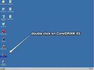
Lecture №23-24. CorelDRAW Basics and Interface 1 Exploring the CorelDraw Screen 2 Moving Around and Viewing Drawings 3 Customizing Options Графика GDI+
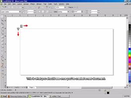
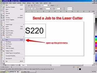
Purpose: Exploring the CorelDraw Screen and working with menu Keywords: useful file name, document size, color mode, Stroke Color, Stroke Width, Laser Cutter
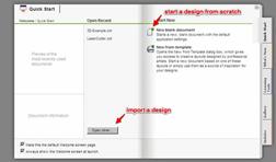
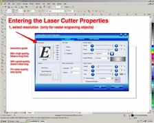
2. New Document Properties Menu
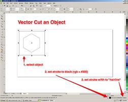
will etch the deepest - обцарапает глубоких will not etch at all - травления не будет вообще
Слайдтар: CorelDRAW Basics And Interface
Ұсынылатын әдебиеттер тізімі: 1. Bryant, Michele Wesen, Fashion Drawing: Illustration Techniques for Fashion Designers, Pearson, Prentice Hall, 2011. 2. Peter A. Koenig, Design Graphics, Drawing Techniques for Design Professionals, Third Edition, Doorling Kindersley, India Pvt. Lt., 2012. 3. templates/ 4. http://www.designersnexus.com/design/free-fashion-croquis-templates/female-fashioncroquis- 5. http://www.corel.com/corel/pages/index.jsp?pgid=800382&item=resource&listid=13600110 Бақылау сұрақтары: 1.How do you Using the Epilog Print Driver 2.How do you Setting up an Object to Raster Engrave 3.discuss Setting up an Object to Vector Cut 4.What do you should have for laser cutter documents:
Lecture №25-26 Objects - Creation And Manipulation 1 Outlining & Filling Objects 2 Arranging Objects 3 Using Layers
Purpose: Изучить основные методы работы с папками и файлами в языке C# Keywords: Interactive Blend Tool,, файлы, файловая система, перечисления
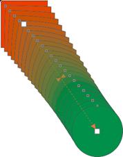
Interactive Blend Tool
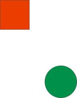
Let us start with the first effect in Corel draw. Interactive Blend Tool blends two objects. We are learning just the basics about blend effect in this lesson. There are lots of details which will be covered in the advanced level. 1. Open Corel DRAW. Select Rectangle Tool and draw rectangle at the top left 2. Select Ellipse Tool and draw circle at the bottom right corner of the window. Fill it with green color.
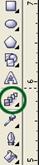
3. Select Interactive Blend Tool (marked with green circle).
4. Now please observe the changes in the cursor carefully. 5. Move the cursor inside the red rectangle. There is a difference between the cursor outside and inside the rectangle. 6. Once the cursor is changed when it is inside the red rectangle, press and drags it. Take it to the inside area of the green circle. 7. A dotted line will form while you drag the cursor and once you release the mouse button, the blend will form between the rectangle and circle.
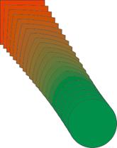
8. Observe carefully that the rectangular shape is smoothly converted into the circle with the gradual steps. 9. At the same time, the red color is also transformed into green using the same steps.
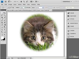
Making A Layer Mask
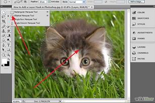
1.Select a layer. Highlight the layer you wish to mask. Make sure the layer is visible, or you will not be able to perform this function.
2. Select an area. Using the the Marquee tool (press M to select it), select the area you wish to reveal. Note that if you want a soft edge, set the Feather radius as desired, before drawing the selection.
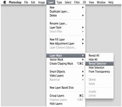
3. Create the mask. Click the Add Layer Mask button at the bottom of the Layers palette. Alternatively, from the Layer menu, choose Layer Mask, then Reveal Selection.
4. After adding the layer mask, the image will look like the one given right. Notice that the kitten's face remains revealed in the top layer, while the rest of the image is transparent, allowing the background layer to show through.
Слайдтар: Objects - Creation And Manipulation Ұсынылатын әдебиеттер тізімі: 1. Digital Darkroom Procedures Using Photoshop CS 2002-638 с. 2. Дэн Маргулис.PHOTOSHOP для профессионалов. Пер. с англ. - М.: 000 "РТВ-Медиа", 2001. - 400 с. 3. http://www.photoshop-master.ru/lessons.php?rub=28&id=1371 4. http://www.photoshop-master.ru/lessons.php?rub=3&id=768 Бақылау сұрақтары 1. How do you using Interactive Blend Tool? 2. How do you using A Layer? 3. How do you Making A Layer Mask?
Lecture №27-28. Working With Special Effects And Texts 1 Special Text Effects. 2.Using Symbols and Clipart 3. Working With Bitmaps Bézier drawing tools 4. Anatomy of a Bézier Path
Purpose: Getting to know the engineering of bézier drawing tools Keywords: compound path, corner points, smooth points, bézier path
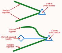
The engineering of bézier drawing tools into graphic and layout programs certainly opens a world of opportunity and creativity for many designers. But, if you’re unfamiliar with the use of these far-from-simple tools, they do you little good. In this tutorial, I’ll showcase the bézier tools included in QuarkXPress to demonstrate to you the power of the bézier drawing tools, and how to control and manipulate the paths they enable you to create with a high degree of flexibility. What Exactly is a Bézier? Anatomy of a Bézier Path As mentioned earlier, path segments can be either straight or curved. Straight segments are simply joined end to end, while curved segments are more involved. The path followed by a curved segment is controlled by the properties of its adjoining points, which can be set to either smooth or symmetrical.
Corner points These are points that enable the shape of segments on either side to be unaffected by each other. In other words, the straight or curved segments can be shaped to allow the path to abruptly change direction where the point joins them, as shown below. For this reason, the corner point is perhaps the easiest to work with.
Smooth points As the name suggests, smooth points force the direction or angle of curved segments on either side to align, creating a smooth transition between the two endpoints, as shown below. Smooth point handles can be set to unequal distances from the point they control. This will apply only where a smooth point joins two curved segments. While a smooth point is in use, the point and both handles will be in alignment.
Symmetrical points These types of points force the curved segments on either side to be equal in slope or angle, as shown below. Unlike smooth points, symmetrical point handles can only be positioned equal distances from the points they control.
Each smooth and symmetrical point features two curve handles. One handle controls the shape of the preceding segment, while the other controls the shape of the segment to follow. Curved segment endpoints-the points at the beginning and ends of each path-contain only one curve handle each to control the respective segment. In an effort to enable you to distinguish which point is which, QuarkXPress displays each of the points and their associated handles in different ways. A corner point takes the shape of a triangle, a symmetrical point is square-shaped, and a smooth point takes the shape of a rotated square, or diamond. Defining Points and Segments While Drawing
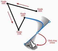
As you click-drag to create a new point, several things occur in the background. First, the point at which you first clicked with the mouse defines the new point’s position, and now as you continue to drag, you’re no longer holding the actual point. Instead, you’re now dragging a curve segment handle that can be rotated 360 degrees around the new point position. By releasing the mouse button, you define the curve handle’s position, in turn affecting the shape of the curve segment you just created -and the next one you’re about to create. The process is ongoing until you’ve completed drawing your path. Choosing a different tool from the main Toolbox, such as the Item tool, ends bézier drawing sessions. Practice makes perfect and bézier tools are no exception to this rule. While drawing using bézier tools, you can also specify a specific point type (other than the default) by holding down the modifier keys that are listed below, while defining each point’s position.
Tip : Holding Shift as a modifier key, while defining a new point, will constrain the preceding segment angle to 90-degree increments. Holding Shift, while click-dragging to define a new curve segment’s point, will constrain rotation of its curve handles to 45-degree increments. Selecting and Editing Paths Whether you’ve created your path from scratch using bézier drawing tools or you’ve converted a box, shape, or text to a path, knowing how the points and line shapes can be changed or transformed is another critical area. Once you’ve created your path, editing the existing points or segments can be a complex process if you’re unfamiliar (or even if you are familiar) with commands for manipulation of the various components. To edit a path, you must use either the Item tool or the Content tool while an open or closed path is selected. Tip : To reposition the entire path while it’s being created, hold down the Ctrl/Cmd key and drag the path. Both points and segments can be repositioned to any point on or off your layout page simply by dragging (or using the nudge keys), while the shape of curve segments can be altered by dragging their curve handles. To make the editing process even more important, straight segments can quickly be converted to curves or vice versa. Plus, the conditions of points can be interchanged between corner, smooth, and symmetrical states. Common commands for this type of editing can be found in a number of places. To find them, select Point/Segment Type from the Item menu, which only becomes available while a point or segment is selected. But perhaps the most crucial companion to have around when editing points is the Measurements palette (press F9). The Measurements palette, as shown below, provides quick access to nearly all properties associated with points and segments, including fields for entering exact point or handle page positions, and buttons to set the condition of points and/or segments. The palette itself has been organized into two distinct areas.
The left side of the palette includes the following controls: § X and Y: These two fields display the current vertical and horizontal upper-left page position (relative to your ruler origin) of an invisible bounding box surrounding your selected path. To move the path, simply type in a new value followed by the Enter key. § W and H: These two options set the overall width and height dimensions of your selected path. To change the scale of your path, type in a new value followed by the Enter key. § Angle: This option enables you to perform a rotation of your selected path by entering a degree value followed by the Enter key. Positive values rotate the path counterclockwise, while negative values rotate the path clockwise. The right half of the palette is dedicated to points. The controls are as follows: § XP and YP: These abbreviations represent the vertical and horizontal page position of the selected point (relative to your ruler origin). For precision positioning, type in a new value followed by the [enter] key. § Curve Handle Angle: The boxes labeled with angle symbols represent the angle of the curve handles. The left angle box controls the curve handle affecting the preceding segment, while the right angle box controls the curve handle for the segment to follow. § Curve Handle Position: The two boxes below the point angle boxes enable you to specify the curve handle distance from the point they protrude from. Changing the curve handle positions changes the shape of curve segments. Between these path and point options are five buttons that enable you to change the condition of points or segments. On the top row, three buttons enable you to change the selected point(s) to symmetrical, smooth, and corner points, respectively. Below these, two buttons enable you to change a selected segment from (or to) a curved or straight segment. When you draw a path using any of the bézier drawing tools, the result is always an open path, meaning the first and last points remain unjoined. To join these points and close the path so that it can be filled with an image, text, or color, use the Item tool to select the path, hold down the Alt/Option key, and choose Item > Shape > Bézier Box (fourth symbol from the bottom). If the points are on top of each other (or at least close together), the endpoints will become joined automatically. Point and Segment Shortcuts
Bézier paths give you exacting measures and a high degree of control and flexibility unafforded to you by other drawing tools. And combining the background information here with a little practical experience on your part should get you started on the road to creativity and control.
Слайдтар: What Exactly is a Bézier? Ұсынылатын әдебиеттер тізімі: 1. Peter A. Koenig, Design Graphics, Drawing Techniques for Design Professionals, Third Edition, Doorling Kindersley, India Pvt. Lt., 2012. 2. http://coreldesigner.wordpress.com/2009/06/01/get-snapping-with-coreldraws-object-snapping-features/#more-597 Бақылау сұрақтары 1. What Exactly is a Bézier?
|
|||||||||||||||||||||||
|
|
Последнее изменение этой страницы: 2016-12-11; просмотров: 256; Нарушение авторского права страницы; Мы поможем в написании вашей работы! infopedia.su Все материалы представленные на сайте исключительно с целью ознакомления читателями и не преследуют коммерческих целей или нарушение авторских прав. Обратная связь - 18.224.66.85 (0.014 с.) |


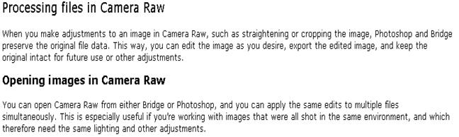
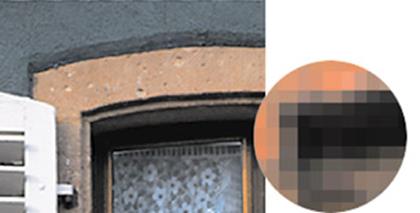 Pixels in a photographic image / Пикселов в фотографическом изображении
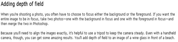
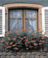
 4 in. x 6 in. at 72 ppi; file size 342K/ 100% on-screen view

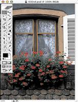
 4 in. x 6 in. at 200 ppi; file size 2.48 MB 100% on-screen view