Заглавная страница Избранные статьи Случайная статья Познавательные статьи Новые добавления Обратная связь FAQ Написать работу КАТЕГОРИИ: ТОП 10 на сайте Приготовление дезинфицирующих растворов различной концентрацииТехника нижней прямой подачи мяча. Франко-прусская война (причины и последствия) Организация работы процедурного кабинета Смысловое и механическое запоминание, их место и роль в усвоении знаний Коммуникативные барьеры и пути их преодоления Обработка изделий медицинского назначения многократного применения Образцы текста публицистического стиля Четыре типа изменения баланса Задачи с ответами для Всероссийской олимпиады по праву 
Мы поможем в написании ваших работ! ЗНАЕТЕ ЛИ ВЫ?
Влияние общества на человека
Приготовление дезинфицирующих растворов различной концентрации Практические работы по географии для 6 класса Организация работы процедурного кабинета Изменения в неживой природе осенью Уборка процедурного кабинета Сольфеджио. Все правила по сольфеджио Балочные системы. Определение реакций опор и моментов защемления |
Induction brazing and solderingСодержание книги Поиск на нашем сайте Brazing and soldering is a method of joining metals by applying a filler metal of low melting temperature between the metals to be joined. When the filler metal melts it slightly diffuses into the base metals thus holding the parts together. Soldering is divided into two classifications: soft and hard. In soft soldering filler metals with low melting temperature are used, while in hard soldering the melting temperature of filler metals is comparatively high. In recent years, many complex forgings and stampings have been re-designed to allow fabrication by brazing or soldering of parts produced by mass-production techniques1. Such new designs have often resulted in striking reductions in cost2. In other instances, brazing and soldering have permitted the construction of assemblies too costly or complex to be produced by other techniques. Induction heating has proved to have been a valuable aid in these joining processes for many reasons. Among these are rapid heating and precise heat control. The former offers the possibility of localized heating for joining high-strength components with minimum loss of strength. The latter permits sequential brazing or soldering operations to have been performed effectively. Rapid heating also minimizes discolouration and thus facilitates cleaning. Uniform joints with smooth fillets, obtained by induction soldering and brazing, decrease alloy consumption and produce parts which are identical in appearance3. Frequently, induction brazing and soldering permit a reduction in the required number of holding fixtures. At the same time, the resultant minimum of the fixtures increases their life and maintains their accuracy in alignment of the components to be joined. Basically, brazing and soldering involve fusion of a joining alloy between the surfaces of metal parts to be joined. If the metal surfaces are clean, intimate contact4 is established and the joining material alloys with each surface, forming a joint upon solidification during cooling. The two methods of joining differ primarily in the type and melting temperature of the alloy used to form the joint. In soldering, low-melting-temperature alloys, generally containing lead and tin, permit joints of limited strength to be made at temperatures below 800°F. Soldering with these alloys is often termed "soft soldering" and is used in fabricating radio condenser cans5, radiators, terminal strips, instrument cases, etc., and with the metals to be joined consisting of copper and copper alloys such as brass and bronze, carbon and alloy steels, nickel alloys and clad or plated aluminium. Thorough cleaning prior to and during heating is basic for successful soldered joints. Many joint failures may have been traced directly to poor cleaning and inadequate fluxing. Surfaces to be joined should have been chemically cleaned (freed of heat treatment scale, corrosion products, grease, embedded graphite, etc.) prior to heating, and the joint areas fluxed as soon as possible to avoid contamination from handling or exposure. Suitable fluxes prevent oxidation of the joining alloy and metal surfaces to be joined and also dissolve any residual oxides during heating. They improve the wetting characteristics6 of the joining alloy, thus promoting its free flow upon melting. Zinc chloride and ammonium chloride fluxes in paste form are most frequently used in induction soldering, since they are the most active. Unfortunately, these fluxes leave residues which are corrosive, electrically conductive and hygroscopic. Such flux residues must be thoroughly removed. When this is impossible, as in soldering fine electrical assembly units, rosin or activated rosin-type fluxes which leave non-corrosive and electrically non-conductive residues are used. Fluxes for induction soldering are usually used in paste or liquid form.
1. mass-production techniques - технические методы серийного производства 2. to result in striking reductions in cost - вызывать резкое снижение стоимости 3. identical in appearance - одинаковые по внешнему виду 4. intimate contact — прочный контакт 5. radio condenser can - корпус радиоконденсатора 6. wetting characteristics - характеристики смачивания Exercises I. Use the following words and phrases in sentences of your own:
brazing, soldering, filler metal, to diffuse, soft soldering, hard soldering, to result in, induction brazing, induction heating, cleaning, smooth fillet, flux, paste, liquid, joint, sequential brazing II. Answer the following questions:
1. What is soldering? 2. How does the filler metal hold the parts together? 3. How may soldering be classified? 4. What kinds of filler metals are used in soft soldering? 5. What kinds of filler metals are used in hard soldering? 6. Why has soldering reduced the cost of production of many assemblies? 7. What type of heating is used in soldering or brazing? 8. What are the advantages of induction brazing or soldering? III. Supply synonyms for the following words:
to join, aid, rapid, precise, to decrease, to produce, to improve, clean, melting, clad, promoting IV. Supply antonyms for the following words and translate them into Russian:
adequate, cooling, dirty, to decrease, to destroy, low-temperature, conductive, heating, to assemble, fortunately V. Underline the suffixes and prefixes and translate into Russian the following words:
redesign, fabrication, induction, non-corrosive, effectively, facilitate, non-conductive, costly, frequently, reduction, basically, discolouration, primarily, successful, failures, hygroscopic, thoroughly, impossible, electrically, conductive VI. Find the predicates in the following sentences, then analyze and translate the sentences into Russian: 1. Recently, techniques have been developed for induction brazing in a reducing atmosphere1 to avoid the use of flux and thus the problems of thorough removal of flux residues. 2. There is a special unit for controlled-atmosphere brazing2. 3. In this unit, a purified dry reducing gas, such as hydrogen, enters the unit at the top, displaces the air and surrounds the part to be heated. 4. Upon heating to elevated temperature, oxide films on the metal surfaces to be joined and on the joining alloy are reduced, permitting satisfactory flow of the alloy into the joint by capillary action, thus producing a good bond.
1. reducing atmosphere - восстановительная газовая среда 2. for controlled-atmosphere brazing - для пайки регулируемой газовой средой VII. Make up questions to which the italicized words are the answers:
1. Soft soldering is used in fabricating radio condenser cans and radiators. 2. Brazing and soldering involve fusion of joining alloy between the surface of metal parts to be joined. 3. In soldering, low-melting-temperature alloys permit joints of limited strength to be made at temperatures below 800°F. 4. Ultrasonic energy is used in fluxless soldering. 5. Suitable fluxes prevent oxidation of the joining alloy and metal surfaces to be joined. 6. Precise heat control is used to permit effective performance of sequential brazing or soldering operations. VIII. State the forms and functions of infinitives and translate the following sentences:
l. The metals to have been joined included carbon and alloy steels, stainless steel, cast iron, copper and copper alloys, nickel and nickel alloys and, to a limited extent1, aluminium alloys. 2. The properties of solder may have been changed by addition of some elements such as zinc, aluminium, and phosphorus. 3. A torch should have been used to heat the hard solder and object to be brazed. 4. In order to solder aluminium, flux should be mixed with a special solder used for aluminium. 5. The ternary alloy of silver, copper and phosphorus was largely self-fluxing when used with copper but should have not been used on ferrous metals since it formed a brittle iron phosphide.
1. to a limited extent - в ограниченной мере X. Translate the following text in written form without using a dictionary:
It is interesting to note that brazed joints involving cast-iron parts are more dependably gas-tight and liquid-tight and have strength if the parts are electrolytically treated to remove graphitic carbon from the joining surfaces before fluxing and induction heating. Fluxes containing fluorides and alkali salts, preferably potassium, are generally used for induction brazing, particularly with the silver-brazing alloys. These fluxes, normally used in paste form, become fluid and active below 1100°F, protecting the metal surfaces to be joined, dissolving residual oxides and promoting better flow of me alloy upon melting.
THREADS
Threads are applied for interconnection of machine parts and for transmitting motion from one part to another. When a thread is cut on the outside of a part it is known as an "external" or "male thread". A thread is called an "internal "or "female thread" when cut inside a part. Depending on the shape of the threading tool different profiles of thread are obtained, such as triangular, square or trapezoidal, shown in Fig. 33.
Fig. 33. Profiles of Threads
In practice triangular threads are most widely used. The main elements of a thread are: the angle of the thread, the major, minor and pitch diameters, the depth and the pitch. These elements are shown in Fig. 34.
Fig. 34. Main Elements of a Thread: d1 - minor diameter; d0 - major diameter; d2 - pitch diameter; S - pitch; t2 - depth
The angle of a thread is the angle included between the sides of the thread and measured in an axial plane. The major, or outside, diameter of a thread d0, (sometimes referred to as "full diameter") is the distance between the two extreme outside points of the thread in the direction square to the axis1. The major diameter is the largest diameter of the thread of a screw or a nut.
The minor diameter db being the smallest diameter of the thread, is the distance between the two extreme inside points of the thread measured at the right angle to the axis. The minor diameter is also called the "core diameter" or "root diameter". The pitch diameter d2 is the distance between the two opposite parallel sides of the thread profile perpendicular to the thread axis. The depth t2 of the thread is the distance between the crest and the base of the thread measured normal to the axis, or
t2=(d0-d1)/2.
A crest is the top surface joining the two sides of a thread, while a base of a thread is the bottom surface joining the two adjacent threads. The pitch of a thread is the distance from a point of thread to the corresponding point of the next thread measured parallel to the axis. Screw threads are of both right-hand and left-hand types. In right-hand threads the direction of the thread is from the right to the left. Right-hand threaded screws are turned clockwise to be screwed into a nut, while left-handed screws should be turned counterclockwise to do that.
Fig. 35. Screw Thread: I - single thread screw; II - double thread screw; III - triple thread screw; a, b, с – pitch
In screw fastenings threads are made of various shapes, but always of the triangular type, such as: single thread, double thread and triple thread (Fig. 35). On the type of the latter depends the lead of the thread which is the distance a screw thread advances axially in one turn. On a single thread screw the lead and the pitch are the same; on the double thread screw the lead is twice the pitch, while on a triple thread screw the lead is three times the pitch. The most widely used systems of triangular threads in machine-building are: metric, inch and pipe threads. Each thread has its own angle and application. A metric thread profile resembles a triangle with an angle of 60° at its apex. Such a thread is widely used for bolts and nuts. An inch tread profile has an angle of 55°. This type of thread may be used when making spare parts for foreign-made machines. An angle of 55° is also used with pipe threads. Pipe threads are applied for gas and water pipes, as well as for clutches connecting such pipes. 1. in the direction square to the axis - в направлении, перпендикулярном к оси
Exercises I. Use the following wards and phrases in sentences of your own:
round thread, internal thread, triple thread, profiles of thread, triangular thread, square thread, buttress thread, pitch of thread, right-hand thread, screw thread, single thread, left-hand thread
1. What are threads used for? 2. What types of threads do you know? 3.What are the main elements of a thread? 4. What types of screw threads do you know? 5. What are the most widely used systems of triangular threads in machine-building?
III. Find in the text synonyms of the following words and word combinations:
square thread, trapezoidal thread, major diameter, minor diameter, root diameter IV. Analyse and translate the following sentences:
1. The metal cannot be compressed, but is cold forged into a different form, and what takes place when the thread shaped dies are forced into the metal to form a thread is displacement of the surface which is forced into grooves, that is, the material from the depressions forms the elevations on either side. 2. The V-shaped thread must not be made sharp because the sharp crest of the V-thread is very easily broken, and the taps and dies will not stand long due to the sharp thread. 3. The finished thread is of greater diameter than the original diameter of the wire, which in turn is larger than the diameter of the finished thread at the root. 4. A screw or bolt of a given size has a greater minor diameter and a greater strength if the pitch is fine rather than coarse. 5. The finished product is therefore larger in diameter than the blank by an amount approximately equal to the depth of the thread. 6. This process of rolling threads, grooves and screw blanks is used in the manufacture of many articles in preference to cutting the threads or grooves with ordinary slow-cutting tools or threading dies. V. Make up as many questions as possible concerning the following sentences:
1. During the operation the metal is cold forged into a different form. 2. The finished thread is of greater diameter than the original diameter of the wire. 3. A crest of a thread is the top surface joining the two sides of the thread. 4. A base of a thread is the bottom surface joining the two adjacent threads. 5. In screw fastenings threads are made of triangular type. VI. (a) Read and translate the following text using a dictionary:
The process of rolling screw threads has been greatly developed and its usefulness extended by the rather recent introduction into common use of a material suitable for roll threading. Iron of ordinary quality does not lend itself well to this process on account of its fibrous structure, which makes this material liable to split or fracture under pressure, but in the modern low-carbon steel we find a material in
every way suited to the rapid and economical forming of screw threads. By this process the blank is rolled between two flat dies with their working surfaces grooved to the shape of the thread required, these grooves being cut across the face of the dies at the proper angle to suit the pitch and diameter of the screw.
(b) Retell the text. VII. On the basis of Fig. 38 describe what profiles of thread are obtained depending on the shape of the threading tool. VIII. Giving answers to the following questions describe the main elements of a thread as shown in Fig. 34:
l. What are the main elements of a thread? 2. What is the angle included between the sides of the thread called? 3. What is the distance between the two extreme outside points of the thread in the direction square to the axis called? 4. What is the largest diameter of a thread called? 5. What is the minor diameter of a thread? 6. What is called the "pitch diameter" of a thread? 7. What is the distance from a point of thread to the corresponding point on the next thread measured to, the axis called? 8. What is the depth of a thread? IX. Describe the shapes of threads in screw fastenings on the basis of Fig, 35. GEARS
A gear is a toothed wheel used to transmit rotary motion from one shaft to another. If power is transmitted between the two shafts, the angular velocity ratio of these two shafts is constant and the driving shaft and the driven shaft rotate at a uniform rate. Shafts may be parallel, intersecting, and non-coplanar. Types of gears may be diverse depending upon the above positions of the shafts. Gears may be classified according to their shape and according to the position which the teeth occupy respectively to the axis of rotation. The teeth cut on the face of л gear may be curved, straight or helical. The main types of gears are: bevel gears, eccentric gears, helical or spiral gears, herringbone gears, screw gears, spur gears and worm gears.
Fig. 36. Bevel Gearing
Bevel gearing (Fig. 36) is used to transmit power between two shafts, which liein a common plane and whose axes intersect each other. The axes may be inclined
to each other at any angle, although 90' is the most common one. The teeth of bevel gears may be either straight or spiral. In the straight bevel gears the elements of teeth converge to a common point called the "apex". Eccentric gears operating on parallel shafts are used to transmit a varying angular velocity either continuously or for a portion of revolution.
Fig. 37. Gearing: a - spiral bevel gear, b - hypoid gear
Helical or spiral gears (Fig.37) operate on parallel shafts at high speeds, providing maximum strength of gear teeth for a given width of face. Such gears are heat-treated and then ground to accurate shape and size, necessary for smooth and quiet running at high speeds. The teeth of helical gears, having been cut on a conical surface, curve continually toward or away from the apex of the cone upon which they are cut. These gears closely resemble • bevel gears and are frequently called spiral bevel gears. Similarly to helical gears, herringbone gears also operate on parallel shafts. Herringbone gears have helical teeth radiating from the center of the face towards the sides of the gear body. They are used where high speeds and high gear ratios are necessary. Screw gearing is used for converting some rotary motion into a forward motion, and for connecting shafts which are not intersecting. Spur gears are gears having straight or helical teeth cut on a cylindrical surface at an angle to the shaft axis.
Fig. 40. Spur Gearing: a - parallel shafts
Fig. 39. Spur Gear Wheels with External Gearing
Spur gearing (Fig. 38) is used to transmit power between two shafts, the axes of which are parallel. Spur gearing may be divided into three types such as: external gearing (Fig. 39), internal gearing (Fig. 40) and rack-and-pinion gearing (Fig. 41). Rack-and-pinion gearing serves for converting rotary motion into forward motion and is widely used in lathes. It consists of a rack-and-pinion.
Fig. 40. Spur Gear Wheels with Internal Gearing
Fig. 41. Rack-and-Pinion Gearing
Fig. 42. Worm Gearing
A worm gear (Fig. 42) is a gear having the teeth cut at an angle to the axis of rotation of the gear body and radially in the gear face. A worm gear is driven by a worm which resembles a large screw. Worm gearing is applied for transmitting power between non-intersecting shafts which are at right angles to each other. In practice friction gearing and toothed gearing are most widely used for transmitting power from one shaft to another and for connecting the shafts. Friction gears are used for light and medium powers in machinery which is frequently started and stopped. Their advantages are flexibility and noiselessness. The disadvantages of friction gears are the thrust on the bearings and slippage. Toothed gears are used when a constant speed is desirable and the distance between the shafts is rather small. Transmission of rotary motion is performed by means of shafts and gears or gear trains mounted on them with the help of inserted keys. Shafts may be of different length and diameters. When rotating, the shafts transmit both the rotation and the torque. Gears replace belt-and-pulley drives where positive motion is required. Gear teeth for all types mentioned above are made in mass production by the generating process on specially designed machines. In this process, the cutter used for cutting teeth has the form of a tooth of the mating gear. One of the most important gear-cutting processes is that of hobbing. In this process, the cutter used for hobbing gear teeth is made like a worm with gashes parallel to the axis to provide cutting edges on the worm. Such a cutter is called the "hob".
Exercises I. Use the following words and word combinations in sentences of your own:
a toothed gear, gearing, to hob, to run, to generate, rotary motion, intersecting shafts, spur gearing, bevel gearing, worm gearing, driven shaft, angular velocity, positive motion, inserted key II. Answer the following questions:
1. What is a gear and what is it used for? 2. Where do gears replace belt-and-pulley drives? 3. What types of shafts do you know? 4. V/hat do types of gears depend on? 5. According to what features may gears be classified? 6. What kinds of teeth cut on the gear face do you know? 7. What main types of gears can you enumerate? 8. By what processes are gear teeth produced? III. Choose synonymical groups out of the following list:
velocity, to transmit, to intersect, smooth, to converge, to transfer, speed, to cross, quiet, to approach IV. Underline the suffixes and prefixes and translate into Russian the following groups of words:
controllable, controller, incontrollable; caller, calling, recall; section, sectional; intersect, intersection, non-intersecting V. Translate the following sentences observing different meanings of the words in italics:
1. When the rain has stopped I noticed a worm on the lawn of our garden. 2. Worm gearing is applied to transmit power between shafts placed at right angles to each other. 3. The Great October Revolution broke out in 1917 and liberated the working class in our country from the yoke of capitalism. 4.Eccentric gears are applied for transmitting a varying angular velocity for a portion of revolution. 5. I locked the door of my flat and left the key on the shelf. 6. Gears are mounted on shafts by means of keys. VI. Find in the text English equivalents of:
Передача с внешним зацеплением; передача с внутренним зацеплением; винтовая передача; закладная шпонка; прямой зуб; кривой зуб, винтовой зуб, косой зуб, реечная передача, фрикционная передача, цилиндрическое зубчатое колесо, коническое зубчатое колесо, шестерня с косыми или спиральными зубьями, шестерня с шевронными зубьями, вращательное движение, давление, зубчатая передача, червячная передача VII. Make up questions to which the italicized words are the answers:
I. Modem requirements for gears demand that they run quietly at high speeds. 2. Gear-cutting machines have been developed for the rapid mass production of similar parts. 3. The gear blank is pressed on an arbor and held between centers of the dividing head and the index tailstock. 4. Bevel gearing is used to transmit power between two shafts whose axes intersect each other. 5. Spur gearing is used to transmit power between parallel shafts. VIII. Using the following words and word combinations describe the bevel gears shown in Figs 36 and 37 and explain the difference between their teeth:
bevel gears, to be used, to transmit power, two shafts, axes, to intersect each other, the teeth, to be straight or spiral, Fig. 36, one can see, the straight bevel gears, to converge, a common point, to be called the apex, Fig. 37, a spiral bevel gear, to have helical or spiral teeth, to have been cut, a conical surface, to curve toward or away, the apex, helical or spiral gears, to be applied, operation, parallel shafts, high speeds IX. Giving answers to the following questions describe the difference between gearings shown in Figs 39 and 40:
1. What types of gearings do you see in Figs 39 and 40? 2. What type of gearing do external and internal gearings belong to? 3. Are the teeth in Figs 39 and 40 straight or helical? 4. How must two shafts be placed when external and internal gearings are used for transmitting power between them? 5. What engagement of two gears does an external gearing provide? 6. What engagement of two gears does an internal gearing provide? X. Look at Figs 38, 41 and 42 and describe in detail the difference between the given gearings.
BELT AND CHAIN DRIVES
The belt drive is the most widely used kind of driving on metal-cutting lathes. The belt drive in lathes is used mainly for transmitting rotation of an electromotor from one pulley to another owing to the tension of the belt. For instance, in some lathes drive to the headstock is provided by belts from a motor, the mounting plate of which is allowed to pivot freely so that the belts are tensioned by the weight of the motor.
Fig. 43. Belt Drive Pi, P3 - belt tension
The belt-and-pulley system of transmitting rotary motion is subject to belt slippage and is therefore not positive. Belts are still incorporated in the drive, because of the safety factor inherent in a friction drive and because of the silence, as compared with gearing run at high speeds. Fig. 43 shows a belt drive consisting of two | pulleys A and B, mounted on two parallel shafts which are connected by an endless belt. The pulley A which transmits rotation is called the "driving pulley"* while the pulley В receiving rotation from the pulley A and transmitting it to its shaft is known as "driven pulley."** The friction surface of a driving pulley should be of a comparatively soft material, while that of the driven pulley is usually made of hard material. Such an arrangement ensures the maintenance of the friction surfaces. Otherwise, if the driven pulley were made of the softer material, its surface would be injured and ruined. There are two main kinds of belts such as flat belts and V-belts. Flat belts are made of leather, cotton yarn or rubberized cloth. V-belts manufactured of rubberized cloth are of a trapezoidal shape. They are pulled over the pulleys into special grooves, which considerably reduces their slipping off the pulleys during operation. Therefore this kind of belt finds ever increasing application on metal-cutting tools and is tending to replace flat belts. When a chain is applied there is no rolling contact as with gears. It transmits its tension uniformly to every tooth of the chain gear coming into contact with it. In this case there is no one-tooth action as in gears, and no losses due to rolling friction and the shock of transferring the load from the tooth. The link-belt silent chain can be, and should be, run slack. Belts require a tension in excess of the effective working tension, and to that extent there is a loss of power on the pulley of the shaft. Belts run on1 by inertia and slip and lose power in that way and the less the belt tension is the more it slips, but the link-belt silent chain never slips.
1. Belts run on - ремни набегают * American - driver ** American – follower
Exercises
I. Use the following words and phrases in sentences of your own:
metal-cutting tools, to pivot, to slip, to lose power, tension, of the belt, driven pulley, driving pulley, rubberized cloth, chain gear, slack, to tend, to incorporate, inertia, to ruin, to injure II. Answer the following questions:
1. What is the belt drive used for and in what machines? 2. Because of what feature is the belt-and-pulley system of transmitting rotary motion not positive? 3. Owing to what features are belts still incorporated in the drive? 4. What are the main two types of belts? 5. What are different belts made of? 6. For what purpose are V-belts pulled over the pulleys into special grooves? 7. How does a chain transmit its tension to every tooth of the chain gear which comes into contact with it? 8. What are the advantages of a link-belt silent chain over a belt? III. Underline the suffixes in the following words and state to what part of speech they belong:
tension, pulley, friction, widely, endless, manufacture, special, slipping, effective IV. Connect the following sentences using participle constructions and gerundial constructions: Example: 1. V-belts are of a trapezoidal shape. They are made of rubberized cloth. V-belts made of rubberized cloth are of a trapezoidal shape. 2. V-belts are pulled over the pulleys into special grooves. The special grooves reduce slipping of V-belts. V-belts are pulled over the pulleys into special grooves for reducing slipping of V-belts.
1. The belt drive is used for driving lathes. The belt drive transmits rotation of an electromotor from one pulley to another. 2. The chain transmits tension to every tooth of the chain gear coming into contact with it. The chain is applied on the lathe. 3. The lathe is provided with an electromotor. The electromotor sets in motion the belt drive. 4. The two pulleys of the belt are mounted on two parallel shafts. The shafts are connected by an endless belt. 5. Flat belts are widely used on metal-cutting tools. Flat belts are made of leather or rubberized cloth. 6. The driving pulley is incorporated in the lathe drive. The driving pulley transmits rotation of an electromotor. V. Translate into English:
1. Следует указать, что ремень тем больше проскальзывает, чем слабее его натяжение и чем меньшую часть шкива он охватывает по окружности. 2. Клиновидные ремни натягиваются по несколько в ряд и укладываются на шкивах в канавки. 3. В токарных станках передачи как клиновидными, так и плоскими ремнями применяются только с натяжным устройством. 4. Передача плоскими ремнями отличается от передачи клиновидными ремнями. 5. Ременная передача в токарных станках применяется главным образом для передачи вращения приводному шкиву от электромотора. VI. (a) Read and translate the text without using a dictionary:
While a motor drive is standard equipment there are certain cases where pulley and belt drive meets the conditions of varied power requirements. It is possible to obtain belt connection with idle pulley and motor mounted in special way. In such a case the 6 inch 6 spindle machine when pulley drive is desired is equipped with 14 inch diameter pulley with 4Ѕ inch face which should run at 760 r.p.m., but the 8 inch 6 spindle machine is equipped with 14 inch diameter pulley with 4Ѕ inch face which should run at 600 r.p.m. (b) On the bash- of this text make up questions and answer them: VIII. Giving answers to the following questions describe the principle of operation of the belt drive shown in Fig. 48:
1. What is shown in Fig. 43? 2. How many pulleys does this drive consist of? 3. Where are these two pulleys mounted and how are they connected? 4. What are the functions of the pulleys used in belt drives? 5. How are pulleys classified depending upon the functions performed by them? 6. What pulley is called the "driving pulley"? 7. What pulley is called the "driven pulley'"?
BEARINGS
A bearing is a machine part which supports shafts and spindles. We know bearings to be classified as plain bearings and antifriction bearings. In plain bearings one friction surface slides upon another. Plain bearings may be of two classes: bearings with a continuous rotary motion and those with an intermittent motion. The first class of plain bearings is represented by journal bearings and thrust bearings. Journal bearings are bearings: carrying a load which acts at right angles to the shaft axis. Thrust bearings take a load acting in the direction of the shaft axis. The second class of plain bearings embraces bearings of parts having a rocking motion, or a linear reciprocating motion. Antifriction bearings are also subdivided in two main classes depending upon the type of rolling elements: ball bearings and roller bearings. In rotating machines, noise and vibration are indications of faulty operation of ball bearings or roller bearings. A ball bearing consists of two rings: an inner ring and an outer ring between which there are hardened steel balls spaced in a ball retainer or cage. If the inner ring had been lifted to a tilt position, the balls would have been forced to climb one side of the raceway during a part of revolution, with resulting drag on the bearing retainer, then, the balls would have accelerated down the raceway to climb the opposite side in the other part of the revolution, reversing the strains on the bearing retainer. In this instance, the balls, instead of rotating about a true horizontal axis, rush to turn from contact with the sides of the raceway and to reverse their direction of turn during the second half of the revolution. In rotating machines, the balls are spaced so that they do not touch each other, thus reducing wear and noise. They require an absolutely parallel raceway to roll upon, entirely free from eccentricity, wobble or other variations.
Fig. 44. Single-Row Ball Bearing: 1 - inner ring or inner race; 2 - outer ring or outer race; 3 - ball retainer or cage; 4 – ball
Ball bearings may be of the following types: radial bearings, thrust bearings, and radial-thrust bearings. In their turn radial ball bearings which serve to take loads acting at right angles to the shaft axis, may be of two types: single-row (Fig. 44) and double-row radial bearings. All the radial bearings are used when high speeds are required. The precision-made radial bearings give the finest service together with a long bearing life. Thrust ball bearings are bearings taking axial loads and giving maximum efficiency with combined journal and thrust loads. They are also recommended for thrust duty1 at high speeds. Radial ball bearings can take both radial and axial loads. In roller bearings hardened steel rollers are used between the rings instead of balls. Roller bearings permit a larger load and have a longer bearing life in comparison with ball bearings. The rollers used in roller bearings may be of different shape: cylindrical, conical, spherical, and concave. Roller bearings, in turn, may be subdivided into single-row and double-row bearings. Bearings with cylindrical rollers are intended to take radial loads, while those with conical rollers may take both radial and axial loads.
1. thrust duty - работа при осевых нагрузках
Exercises I. Use the following words and phrases in sentences of your own:
bearing, plain bearing, to support, antifriction bearing, continuous rotation, intermittent motion, to carry load, rocking motion, journal bearing, linear reciprocating motion, axial load, radial load, hardened steel balls, to touch, to reduce wear, long bearing life, precision-made radial bearings II. Answer the following questions:
1. What are bearings used for? 2. How are bearings classified? 3. How may plain bearings be classified? 4. What bearings belong to the first class of plain bearings and what loads are they intended to take? 5. How are antifriction bearings classified? 6. What bearings belong to the second class of plain bearings? 7. What are the main types of ball bearings? III. Find in the text English equivalents of:
подшипник качения, подшипник скольжения, опорный подшипник, шарикоподшипник, упорный подшипник, однорядный подшипник, роликовый подшипник, сепаратор подшипника, внутреннее кольцо подшипника IV. Give derivatives from the following words and translate them into Russian:
class, to move, to carry, to direct, to rock, to depend, to roll, to retain, to require, fine, axis, efficient, long, cylinder, cone, to determine, assembly V. Find the predicates and state the forms and functions of infinitives in the following sentences. Translate the sentences into Russian:
1. We know taper roller bearings to have been manufactured by many plants, in both single- and double-row types, each with plain and flanged outer rings, in a range of sizes covering bore diameters from 35 to 210 mm. 2. We also know taper roller bearings to have been designed and manufactured for use on machine tool spindles where a high degree of accuracy coupled with rigidity and cool running over a range of speeds is demanded. 3. The cage is centred on the inner ring to allow only a small proportion of the oil to flow along the bearing tracks for lubrication purposes. 4. We have noticed that some balls made of special steel increase their hardness. VI. Find the predicates and state the kind of subordinate clauses in the following sentences and translate them into Russian:
1. These bearings are finding other applications where similar characteristics are necessary, for example in printing machinery. 2. Among the features of these bearings are the hollow rollers which, together with special cage construction, ensure that full use is made of the oil flow for lubricating and cooling purposes. 3. A light alloy cage, the surface of which has oil retaining properties, is employed and almost entirely encloses the rollers occupying practically the whole space between the inner and outer rings. VII. Change the following sentences using the subordinate clauses instead of the complex objects and translate them into Russian: Example: We know bearings to be subdivided into several classes. We know that bearings are subdivided into several classes.
1. We know a bearing to be a machine part for supporting shafts and spindles. 2. We know bearings to be classified as plain bearings and antifriction bearings. 3. I find in plain bearings one friction surface to slide upon another. 4. I have noticed thrust bearings to take a load acting in the direction of the shaft axis. 5. I know antifriction bearings to have been subdivided into two main classes. VIII. Translate the following sentences into English using the complex object: Example: Мы предполагаем, что они окончили новую конструкцию сепаратора подшипника. We suppose them to have completed a new design of the bearing retainer.
1. Мы знаем, что опорами валов и шпинделей служат подшипники. 2. Мы знаем, что подшипники подразделяются на подшипники качения и подшипники скольжения. 3. Мы предполагаем, что подшипники скольжения получили свое название из-за вращения вала по внутренней поверхности вкладыша. 4. Мы ожидаем, что трение, нагрев и износ подшипников уменьшится при применении обильной смазки. 5.Общеизвестно, что, для того чтобы обеспечить различные условия работы шпинделя, вкладыши подшипников изготовляются из различных материалов. IX. (a) Read and translate the text without using a dictionary:
Automatic assembly and inspection machine for antifriction bearings. The range of air-operated gauging equipment made by some plants for checking ball and roller bearings is being extended to include fully- and semi-automatic machines for carrying out assembly as well as inspections on most types of precision antifriction bearings. One of the new machines for automatic assembling and inspecting taper roller bearings is discussed below. On this machine, the inner race is automatically checked for diameter, and rollers of the required size are selected. Assembly of the race, rollers and cage is next carried out to produce a bearing with predetermined clearance. The bearing is then checked for torque, noise level1, and assemblies which are not acceptable are automatically rejected.
1. noise level - уровень шума (b) Retell the text.
X. Using the following words and word combinations describe the construction of the ball bearing shown in Fig. 44:
single-row bearing, to be represented, this picture, to consist, two rings, an inner ring, an outer ring, there are, these rings, hardened steel balls, to be placed, each other, to reduce, this feature, wear and noise, balls, to require, to roll upon, parallel raceway, free from wobble
CLUTCHES
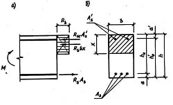
A clutch is a device for connecting two parts, such as shafts or a shaft and a pulley. The difference between a coupling and a clutch is that a coupling is used to connect two shafts permanently, while a clutch may ensure easy and quick connection and disconnection of two shafts. Clutches used in lathes are subdivided into several types, such as rigid couplings and disengaging clutches. A. rigid coupling serves for connecting coaxial shafts which are not disengaged in the. process of operation. Fig. 45 shows a rigid coupling, which consists of a solid bushing connecting electric motor and lathe shafts by means of a key. Disengaging clutches are applied in lathes for temporary engagement and disengagement of a shaft and parts connected with it. They are divided into friction clutches and yaw clutches. Friction clutches serve to connect а stationary machine part to transmit the required power. Sometimes friction clutches are intended as safety devices to prevent the breakage of parts in the transmission train.
Fig.45. Rigid Coupling: 1- electric motor shaft; 2- solid bushing; 3- lathe shaft
Fig. 46. Cone Clutch: 1 - toothed wheel; 2 - cone disc; 3 - movable wheel; 4 -eccentric clamp; 5 – spring
Friction clutches may be divided into two groups, according to the direction of the acting force: axial clutches and radial or rim clutches. In axial clutches the contact pressure is applied in a direction parallel to the axis of rotation, while in rim clutches the contact pressure is applied upon a rim in a radial direction. Axial clutches can be subdivided into cone clutches, and combined cone and disc clutches. Fig. 46 shows a cone clutch. By moving a movable wheel the cone disc connected with the toothed wheel by a key may engage the cone located in the movable wheel. Thus the cone disc is pressed against the inside cone of the movable disc, friction necessary for transmitting rotary movement to the movable wheel being created between the two cones. The outside cones are meshed by an eccentric clamp. By turning the eccentric clamp to 90° the friction clutch is disengaged, a spring pressing out the toothed wheel from the friction disc. Radial or rim clutches may be classified as band clutches, block clutches, and as external, internal, and combined internal and external clutches. Jaw clutches consist of two half-clutches – a. fixed one and a movable one which have jaws on their faces. The fixed half-clutch is rigidly fastened on one shaft, the movable one being keyed to another shaft. The shafts are connected through the coupling of jaws on both half-clutches. The following factors are decisive in selecting the type of clutch to be used: torque, rotative speed, available space, and frequency of operation. When a heavy torque should be transmitted a clutch must have sufficient gripping power, which is usually ensured by multi-disc clutches. For low-speed service cone and rim clutches are used. For high rotative speeds light, compact and internally balanced clutches of the multi-disc type may be applied. Space being limited, multi-disc, twin-cone and double-cone clutches are used because of their greater compactness in comparison with other types of clutches. Single-disc clutches with metal contact surfaces and cone clutches are the most suitable ones for frequent or continuous operation.
Exercises
I. Use the following words and phrases in sentences of your own:
clutch, coupling, rigid coupling, disengaging clutch, coaxial, key, friction clutch, transmission train, axial clutch, rim clutch, jaw clutch, to engage, fixed clutch, eccentric clamp, suitable II. Retell the text giving answers to the following questions:
1. What is the difference between a clutch and a coupling? 2. How are clutches subdivided? 3. What does a rigid coupling serve for? 4. What is a disengaging clutch applied for? 5. What is a friction clutch? 6. How are friction clutches classified? 7. What is the difference in application of the contact pressure in axial clutches and in radial clutches? III. Choose synonymical groups out of the following list:
rigid, to connect, frequently, different, to engage, tendency, to join, various, hard, to gear, often, direction, rotation, transmission, revolution, transferring IV. Choose antonymical groups out of the following list:
to divide, movable, to engage, external, to connect, immovable, to disconnect, to unlink, to stop, internal, to start, to combine V. Underline the suffixes and prefixes and translate into Russian the following words:
engage, engagement, engaging, disengaging, disengagement; determination, predetermination; station, stationary; intensity, intensive; rigidly, rigidity VI. Connect the following sentences using the absolute participle construction and translate them into Russian: Example: A rigid coupling connects coaxial shafts. Coaxial shafts are not disengaged in the process of operation. A rigid coupling connecting coaxial shafts, they are not disengaged in the process of operation.
1. The construction of some new clutches has already been completed. We ordered some of them. 2. Numerous experiments have been carried out. The design of the new jaw clutches was approved. 3. The clutches used in lathes are subdivided into several types. The friction clutches are subdivided into two groups. 4. A spring presses out the wheel from the disc. By turning the eccentric clamp, the cone clutch is disengaged. 5. Clutch constructions are based on the positive-action and friction principles. Couplings are made in two main types: rigid and flexible. VII. Translate the following sentences into English using the absolute participle construction: Example: Когда расстояние между валами ограничено, используются многодисковые муфты. The distance between shafts being limited, multi-disc clutches are used.
1. Так как некоторые валы имеют небольшое отклонение от соосности, применяется упругое соединение. 2. Схематическое устройство конусной фрикционной муфты показано на рис. 46; конический диск может при перемещении подвижного колеса входить во внутренний конус. 3. Когда кулачковая муфта включена влево, вращение от ведущего вала передается ведомому валу через колеса. 4. Если кулачковую муфту включить вправо, то вращение передается ведомому валу через зубчатые колеса. 5. Так как кулачки легко повреждаются, кулачковые муфты переключаются только при остановленном станке. VIII. Translate the following sentences into Russian observing different meanings of the word "part":
1. The part of the work was completed in time. 2. The second part of London's complete works has been published. 3. This part of the machine was worn due to bad lubrication. 4. They part when he goes to sea. 5. They took part in a discussion on the manufacture of new clutches. IX. Translate the following text in written form using a dictionary:
The multi-disc clutch is usually equipped with automatic cone brake. Moving the clutch control handle to the left compresses the clutch driving discs to set the lathe driving shaft in motion. To disengage the clutch, the clutch control handle should be moved to the right. The clutch driving discs then automatically separate and the brake takes hold to stop the lathe driving shaft with a smooth, quick stop, holding it rigid for ease in locking work in chuck or other operations requiring a fixed spindle. When necessary to turn the spindle by hand, it may be entirely disconnected from the driving shaft by throwing the lathe's regular gearshift handles into their neutral position1. The speed with which the brake will stop the lathe is affected by weight of the workpiece that is in the lathe.
1. throwing... into neutral position - переключением... их в нейтральное положение X. Using the following words and word combinations describe the clutches in Figs 45 and 46:
a rigid coupling, to be represented, Fig. 46, to consist, a solid bushing, to connect, electric motor, lathe shafts, a key, axial clutches, to be subdivided, cone clutches, disc clutches, to be shown, the cone disc of the cone clutch, to be connected, the toothed wheel, to engage the cone, to be located, the movable wheel, friction necessary, to transmit rotary motion, to be created, the two cones, to be meshed, an eccentric clamp, the friction clutch, to be disengaged, the eccentric clamp, to be turned to 90°, a spring, to press out, friction disc
CHAPTER IV METAL-CUTTING MACHINES
LATHES
A lathe is known to be essentially a machine tool for producing and finishing surfaces of workpieces. The machine is designed to hold and revolve work around an axis of rotation so that it maybe subjected to the action of a cutting tool moving in a horizontal plane through the axis of the work. When the cutting tool moves in a longitudinal direction or parallel to the axis, the operation is known as "turning"; when it moves in a transverse direction, it is known as "facing". In addition to turning and boring, which the machine is primarily designed for, many other operations, such as drilling, threading, tapping, and by employing special adapters grinding and milling, may be performed on a lathe. Lathes used in shop practice arc known to be of different designs and sizes. These lathes fall into various types, either according to their characteristic constructional features, or according to the work for which they are designed. The size of a lathe is determined by the diameter and length of work that may be swung between centers. Lathes of comparatively small size, which may be mounted on a bench, are termed bench lathes, and are intended for small work of considerable accuracy; lathes provided with tools held in a revolvable turret are called "turret lathes": lathes in which workpieces to be treated are held in a chuck are known as "chucking lathes"; lathes in which most of operations are performed automatically are named "automatic lathes ".
Fig. 47. Engine Lathe: 1 - feed gearbox; 2 - feed selection levers; 3 - headstock and gearbox; 4 - speed change levers; 5 - spindle; 6 - live center; 7 - sliding hand traverse; 8 - tool rest; 9 - tool post; 10 - cross-slide lever; 11 - compound rest; 12 - saddle: 18 - tool rest lever; 14 - dead center; 15 - tailstock; 16 - electric motor; 17 - feed shaft; 18 - lead screw; 19 - sliding feed lever; 20 - apron; 21 - bed
Besides there are also many special-purpose lathes such as crankshaft lathes and wheel lathes for turning crankshafts or engine driving wheels respectively; screw-cutting lathes for threading screws, etc. The engine lathe (Fig. 47) used for metal- turning operations is fitted with a power-actuated carriage and cross-slide for clamping and holding the cutting tool. In engine lathes the cutting tools are generally guided by the machine tool itself, in other words, they are operated mechanically, while in some lathes the cutting tools are guided by hand. The engine lathe consists essentially of the following basic parts: the bed, the headstock, the tailstock, the feed mechanism, and the carriage.
Fig. 48. Bed: 1.5- ribs; 2,7- casting walls; 3.6- V-type ways; 4- flat way
The bed (Fig. 48) is a rigid casting with two longitudinal walls firmly connected by cross ribs integral with the casting. The bed serves as a base to support and align the rest of the machine. The upper surface of the bed is provided with parallel V-type and flat ways or guides for accurate aligning of the sliding parts of the lathe - the carriage and the tailstock. The headstock is located and firmly bolted to the left-hand side of the bed and carries a pair of bearings in which the spindle rotates. Many modern lathes have a motor built into the headstock with the spindle serving as the motor shaft. The spindle (Fig. 49), being one of the most important parts of a lathe, is a steel hollow shaft with a taper bore for the insertion of the live or running center on which the piece to be turned is placed. The other end of the work is supported by the non-rotating dead or cup centre. The nose of the spindle is accurately threaded for chucks to be screwed on it. The chucks, in turn, hold and revolve workpieces together with the spindle. The headstock also incorporates the change gearbox driven by a set of speed change levers. The change gearbox serves for running the lathe at different speeds required in turning and boring workpieces of various diameters.
Fig. 49. Spindle: 1 - hollow shaft; 2 - live center; 3 - thread; 4 - through hole
The tailstock (Fig. 50) located at the right-hand side of the bed, is a casting carrying a non-rotating sleeve, which together with the nut can be advanced or retracted by means of the tailstock revolving screw operated by the handwheel. The tailstock may be moved anywhere along the lathe bed and can be clamped in place at any point. On changing the position, the tailstock slides along the two inner bed ways one of which named flat way is of rectangular cross-section and the other one is of V-section. The t
|
||||||||||||
|
|
Последнее изменение этой страницы: 2016-08-12; просмотров: 431; Нарушение авторского права страницы; Мы поможем в написании вашей работы! infopedia.su Все материалы представленные на сайте исключительно с целью ознакомления читателями и не преследуют коммерческих целей или нарушение авторских прав. Обратная связь - 216.73.216.214 (0.015 с.) |